Which type of z-spindle coupler do you use? I had such a behavior (but every layer equal) on my Ordbot Hardon when I used the cheap spiral aluminium cupplers. It was gone after I replaced them with the better (uncompressable) ones.
While the print hasn’t yet finished, I can tell that the problem isn’t resolved by PID tuning. From the periodicity, I was afraid it might not resolve it.
Good call! It is in fact the cheap aluminum spiral kind; one of the few parts I used from the old gantry printer in order to stick to my original “leftovers” design constraint. I think it theoretically shouldn’t matter whether they are compressible, because the motor doesn’t support the Z axis; the Z axis rests on a bearing, with the motor floating below it. But I wouldn’t be surprised if slop in the bearing is being played by the coupling; the motor isn’t perfectly aligned due to some design mistakes I made earlier (not accounting for the difference in thickness between making my own motor mount from aluminum angle vs. a thinner purchased steel motor mount).
I can and should play with shims a bit more to improve the alignment. I could also try pulling the motor down a bit, opening up the spirals on the coupling, so that it’s always loading the Z stage reference bearing in the same direction.
I’ve ordered a spider (lovejoy style) coupling, but it might be better to put the spiral aluminum coupling in tension, better aligned, in order to preload the Z reference bearing to remove backlash.
…I did shim for better alignment. Now the motor shaft slides into the coupling smoothly without obviously displacing it at all. But it turns out that the motor obscures the screws for the motor mount, so I can’t easily preload the bearing by stretching the coupler. I haven’t gotten enough printed to tell whether it’s better or worse, but at least the problem hasn’t gone away entirely.
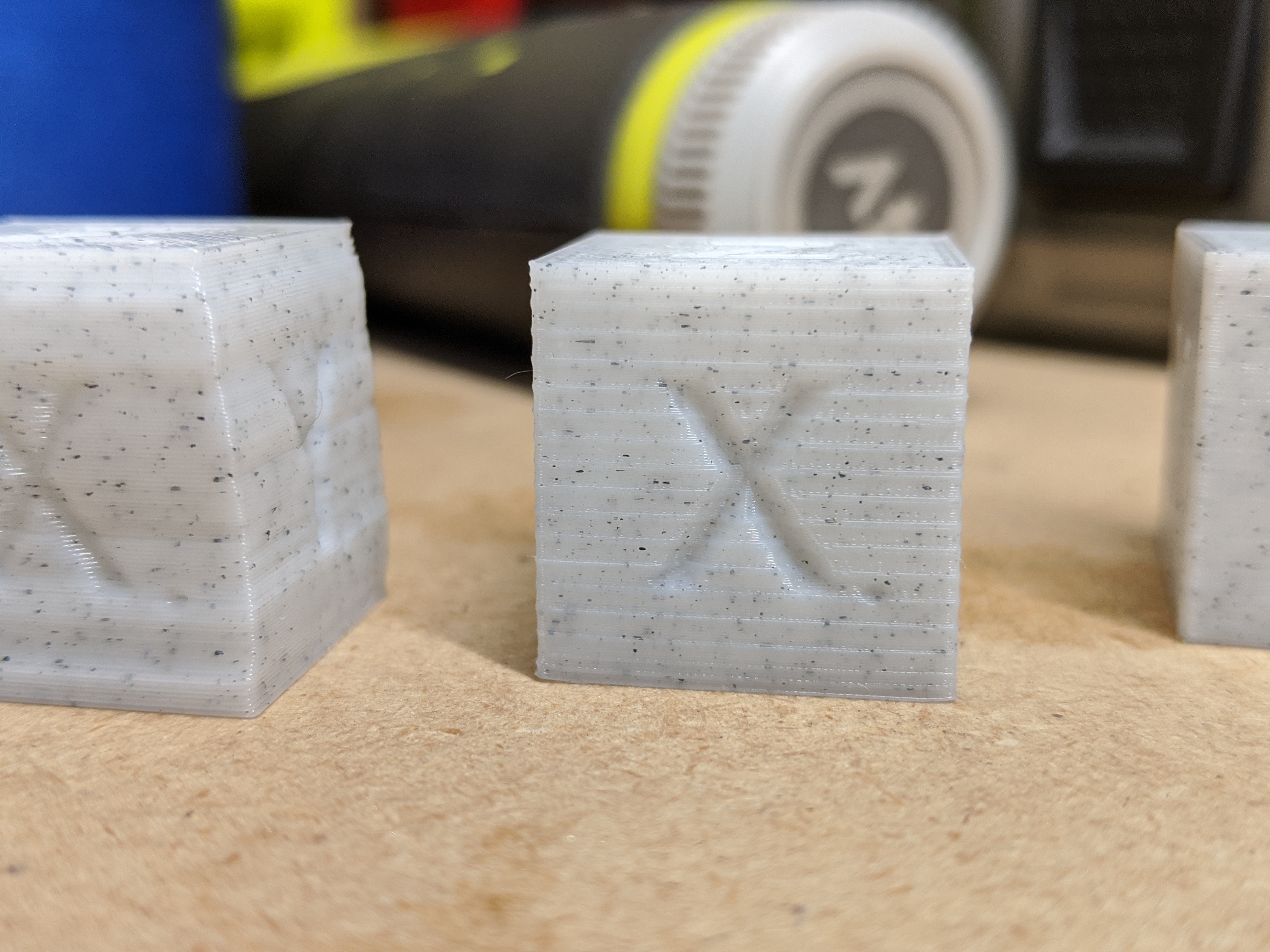
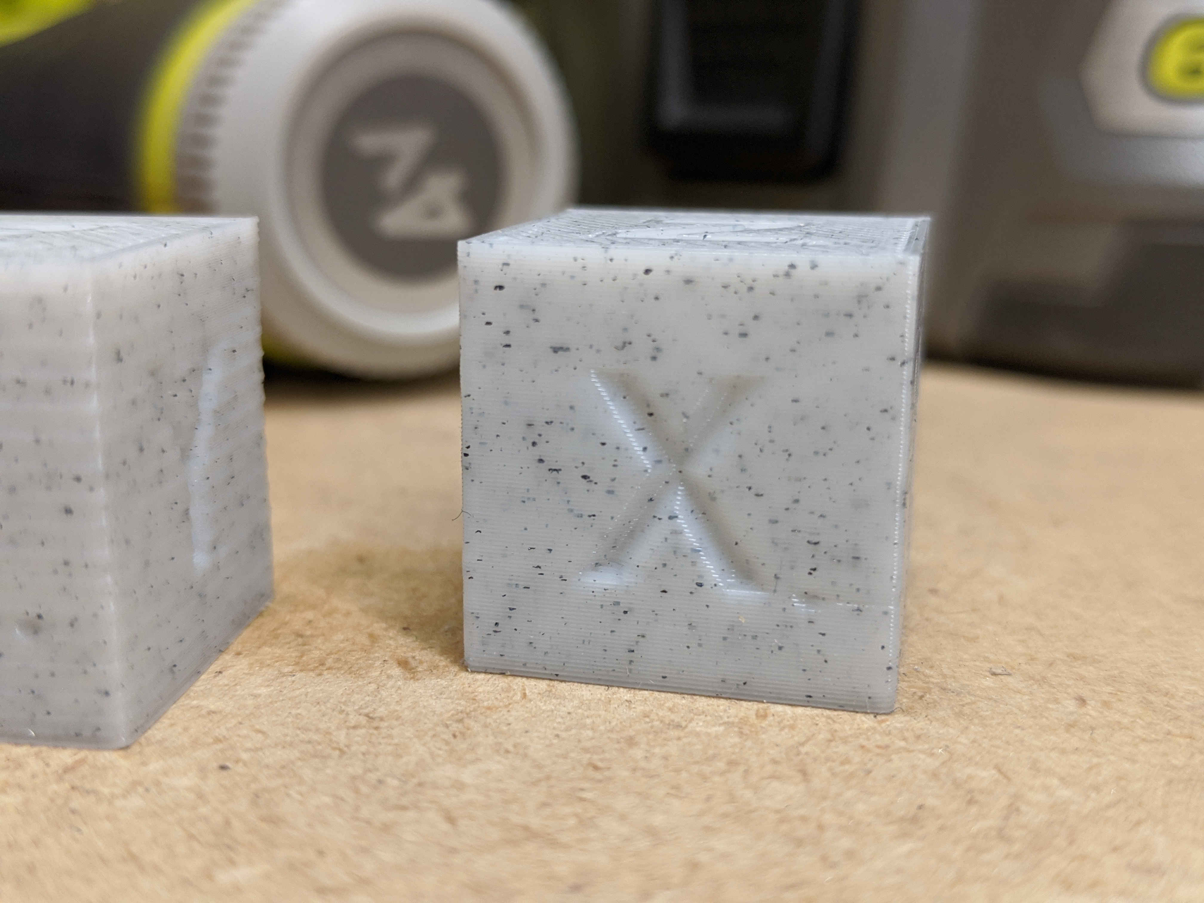
It’s mildly better, but also I can still see mis-alignment of the coupler from another angle. First version on the left, second on the right:
I started taking apart the Z axis to add more shims. I removed the stepper motor. Then as I loosened the screws holding the ball nut to the Z lift plate, the whole Z stage self-drove down.
Then I was able to see that I had yet another misalignment problem I hadn’t seen before, also due to trying a “shortcut” of not building my own mounts and altering the design to fit. I hope this time I get it straight.
1 Like
With the cheap spring couplers I find if you preload them a bit it makes a pretty big difference. So tighten it onto the motor shaft and then pull it up the 8 mm shaft and then tighten it down so it pulls itself down to the motor shaft. You only really need the spring miss alignment for x and Y but having it pre-loaded on z means that the springiness of the coupler shouldn’t affect the hops and fast z moves.
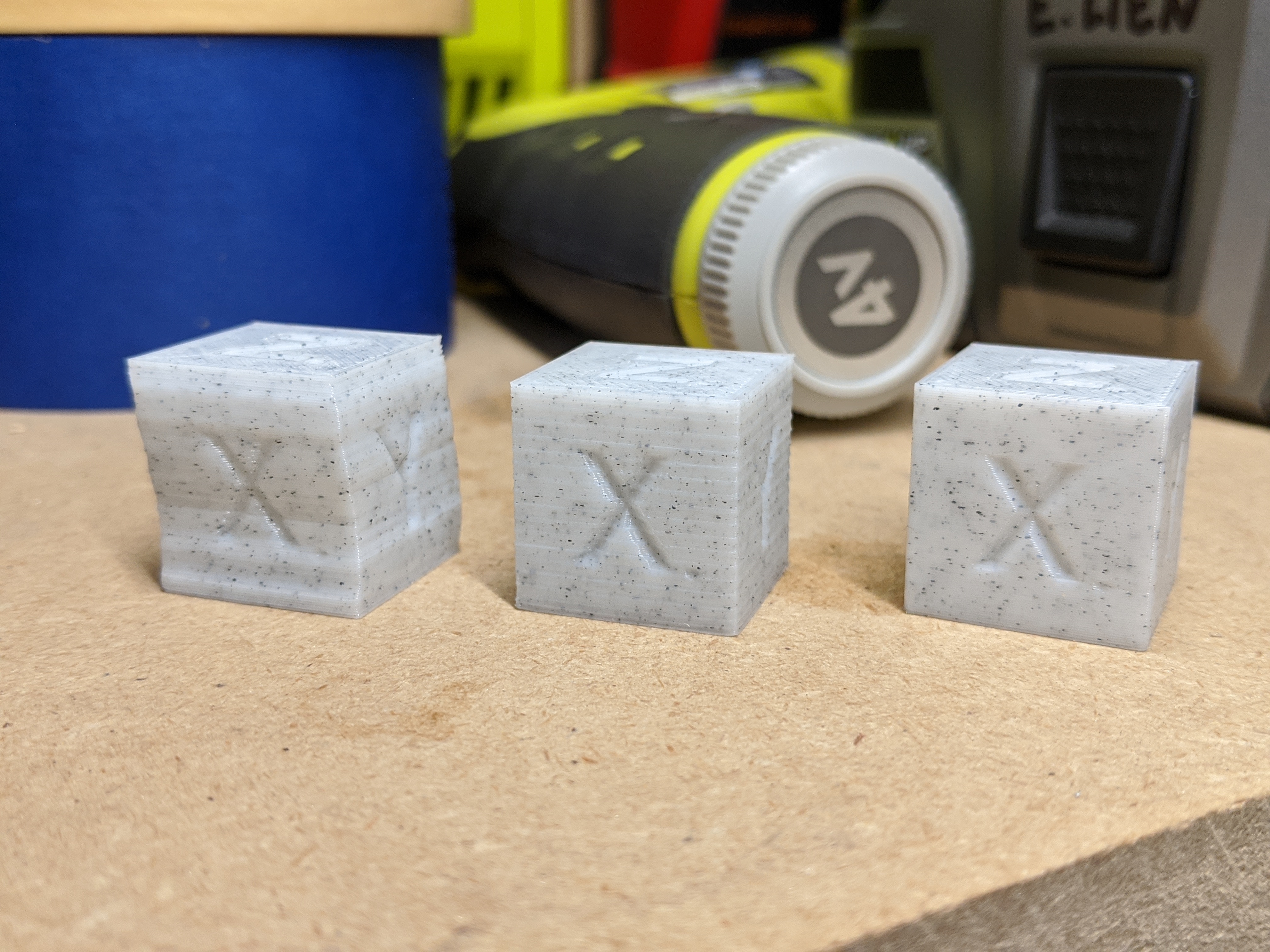
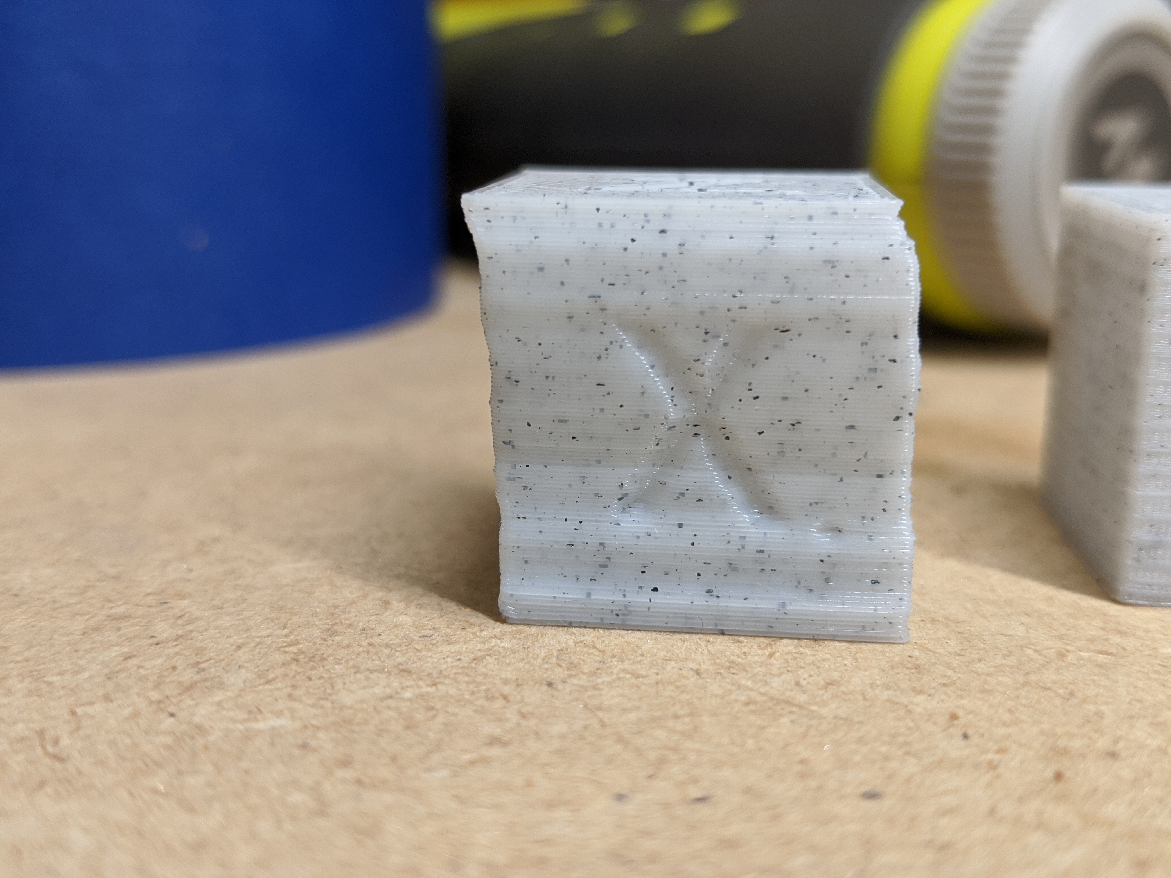
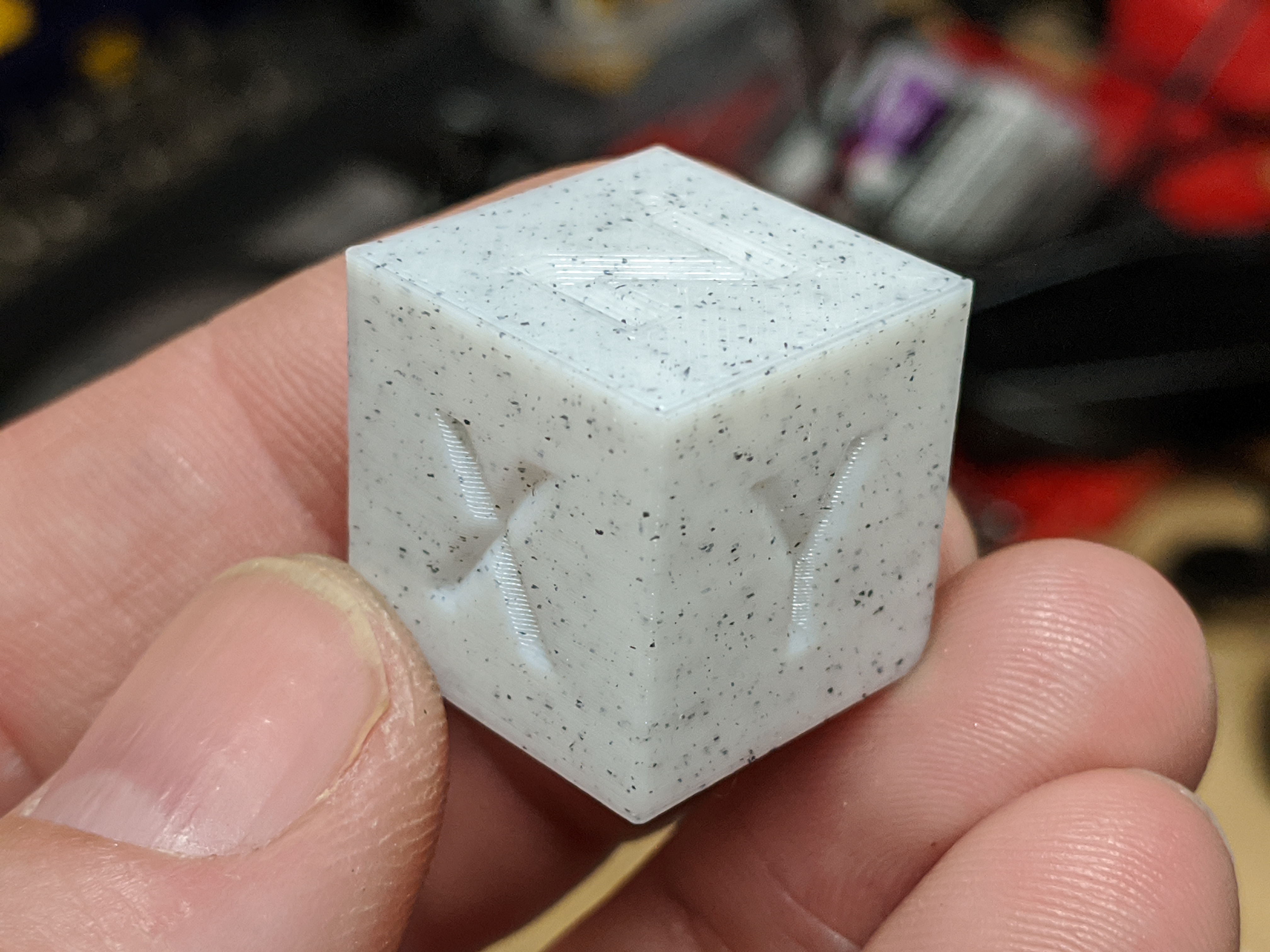
Also double-check your currents on the motors. When I recently rebuilt the adoptabot I had a pretty substantial difference in print quality just by changing motor current and nothing else. Left to right in the image below is upping my x,y, and z motor current.
I found quite the litany of Z stage problems so far. So many, in fact, that it’s possible that I am not remembering them all. ![]()
- My ball nut was not square to the Z linear rail it must align with; this alone prevented it from running free, and I could feel clicking from the balls entering the race. A couple small shims seem to have resolved that problem.
- My bearing seat wasn’t perfectly aligned in Y with my ball nut, by over 1mm, and it couldn’t be aligned with the NEMA17 motor mount I had re-purposed to hold it. I had to mill out a mounting slot wider, and stack a wider washer on the mounting screws, to move the mount far enough to make the bearing seat align in Y.
- My stepper motor, for the same reason as the bearing seat and by the same amount, needed its motor mount slot milled out to align with the ball screw.
- I had the motor shaft and ball screw shafts nearly touching inside the coupling, making the flex in the coupling almost completely unusable. I marked both shafts with sharpie before re-assembling so that I would not repeat that mistake.
Today I (Re)Learned
The tight tolerances of even a relatively low-quality ball screw system are a very poor match for fly-by-the-seat-of-your-pants re-engineering. Almost everything I ran into is directly or indirectly attributable to swapping out making my own mounts for mounts that I purchased in an expectation of saving time.
I would probably have seen none, or nearly none, of these Z artifacts had I just opted for single-start T8*2 lead screw as I have done in other printers. I even had some that I had previously installed as an upgrade in the junk gantry printer that I tore down at the beginning of this project. $20 could get me a new 400mm T8x2 plus an anti-backlash nut, ordered on amazon, and arriving in a few days.
If my rebuild of the Z stage doesn’t resolve, or mostly resolve, these artifacts, I may do just that. The only reason I would hesitate is that I would have to work out what to do about fitting it to the Z lift plate designed for the ball screw nut.
If I do get this printer working well enough to consider creating a new design that others could build, I’ll be making changes from lessons learned, and I won’t inflict the ball screw on others in such a design.
The “design” of my Z stage makes it almost impossible to effectively preload Z. I managed to add some pre-load on reassembly, but only by leaving the motor mount loose enough to push down the tower, away from the Z bearing, after I screwed the motor into the mount. It’s not clear to me that it will maintain that preload.
Those calibration cubes tell a story!
The motors I got didn’t come with a spec. I was running them at about 1A in the donor printer (analog potentiometer). I’m running them at 800mA in the new printer and could probably run them lower. I’m sensorless homing at 200mA and that might be overkill honestly.
The fact that Y throws around the relatively heavy bed with no problem at 800mA means that X should require substantially less, and Z really doesn’t get much of a workout.
…
This is much better. It’s still printing, but the first 12mm or so are tremendously better. I’ll do more tuning, but at this point I don’t think I’ll even bother swapping in the lovejoy-style couplings when they arrive.
Fixing the Z stage took the time I had expected to use to make a new mount for the extruder, though, so I’m still using the hack.
I haven’t yet decided what to do for mounting the power supply on the other side. I’ll at least want to print a cover for the power so I’m not exposing 120V. But for mounting it to the frame I haven’t decided yet.
…
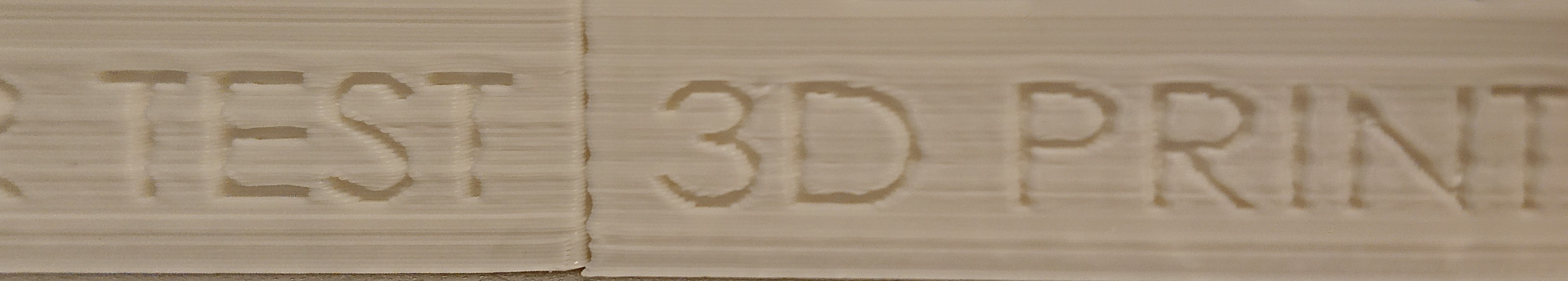
After Z axis fixes on the left, compared to previous print on the right:
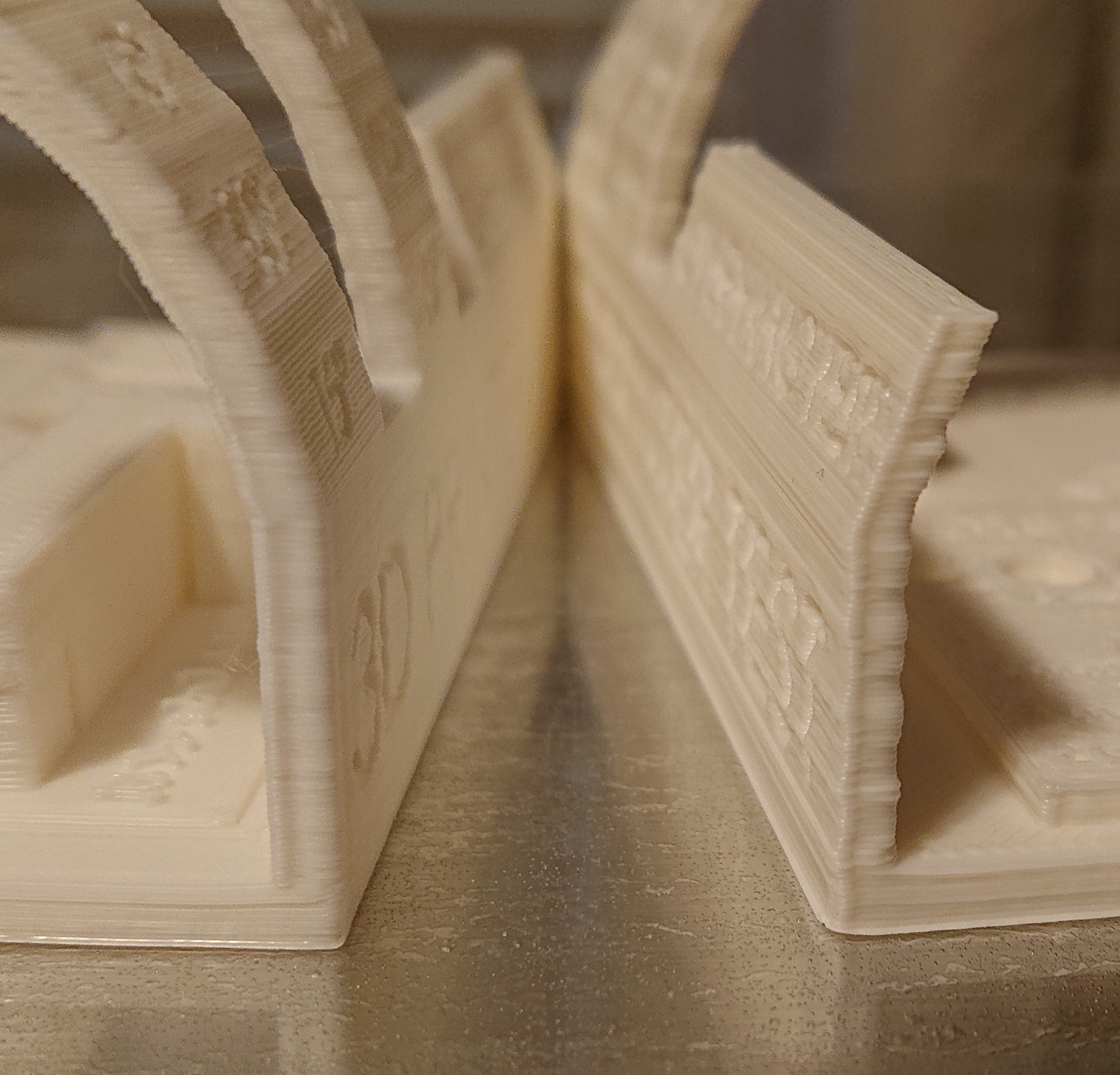
Still need to tune acceleration at least, but the worst problem is resolved.
2 Likes
The amazon description said that it wasn’t thermostatically controlled, but it clearly is, since it cycles on and off while the printer runs.
To decide whether it might ever be worth doing this, or merely redundant, I searched for other cantilever designs. I was surprised at how few there were. None of the few examples I found used a rectangular frame; they all used some form of T or F frame, and were primarily intended to use minimal material. I believe all the examples I found used a smaller bed than mine.
In my design, the rectangular base provides both stiffness and weight counterbalancing the tower, which is itself cantilevered off the side of the frame. The other designs support the tower from both sides, so they don’t need a cantilever counterbalance. When this started out as a gantry design, the rectangular frame made lots of sense. Then when I switched to cantilever, it made sense to keep it in case I needed a small stabilizing tower at the other side of the arm. I still don’t know whether I’ll eventually want to add that stabilizing tower, since I’m still experimenting with quality.
My general design is based on quite a few custom milled aluminum parts, all of which I milled using HNC (Human Numerical Control, manual mill with DRO). It really requires access to a mill, or at least to a good stiff CNC router. Feels to me like the intersection of interest and capability might be low for this machine. I’d think that most people with sufficient interest to build something from scratch including milling custom parts are probably going to go corexy or hbot these days. Hard to spend the time to model it without a reasonable expectation that someone would someday find it useful. Seems like there are so many more objectively better designs out there that started from more meaningful design constraints than “my project leftovers!”
I’d think that the first question would be “How much would it cost to make?” and that I can’t answer without a sense of what someone would charge for a set of aluminum plates. Looking at the various sets of plates Blue Ox (chrisclub1) sells on ebay (e.g. for the OX) my set would be less aluminum but more parts, more complexity, and more tool changes, so $150 feels like it would be on the low side, probably more like $200, not counting the bed. Probably more if some parts need to be cut from something other than ¼" sheet. Then for all the other parts, if I had needed to buy them new, and substituting less expensive and more appropriate T8*2 lead screw for the ball screw, it’s probably over $600 more of BOM. So a finger-in-the-wind total estimate would be a minimum $800 BOM for someone without a machine shop handy, easily $1K by opting for high-quality stuff. My cost to upgrade from what I had already lying around from a few years of other random experiments was under $100 (not counting a few items I refreshed stock on after depleting for this project), which was rather more manageable.
Would anyone spend $800 plus days of time building this when you could, say, get a far more capable FT-6 for substantially less?
1 Like
I guess it depends upon the goal of the builder. I always try and put my stuff out there only because maybe it’ll inspire someone, or they can take the parts that I took the time to model and use them in their assemblies. But you’re right the amount of time it would take to make this a fully documented project probably wouldn’t yield the results you want in the days of ender 3’s. Maybe 5 or 6 years ago, but today the majority of people out there use the printer as a tool not a hobby.
For me a lot of the time it was just the calming aspect of sitting at the CAD station and doing real detailed work, it’s amazing how 5-6 hours can disappear in the blink of an eye when you’re working out the details and making sure everything’s perfectly aligned. But I’m weird like that, I enjoy the process 
Perhaps just take the models of the things that you’re happy with and make any modifications you need to for the cad you’ve already done and put those out there as kind of a free-for-all, grab it if you need it.
2 Likes
I think that this re-build log should suffice for that. I’d say put any spare time/effort into something more personally satisfying. Thank you for taking the time to document your build, mistakes, and solutions. The thought process behind this stuff is what can inspire others to take the plunge, and to take the time to do it right. I’ve enjoyed following along when I have a spare moment to check stuff out. But I suppose I’m more of a lurker than a maker right now. I think I’m getting close to a point where that may change. We’ll see. But stuff like this keeps my interest up and whets my appetite for tackling the old Printbot LC+ v1 parts bin I had designated for a non-sliding bed design of my own creation (with updated electronics, since Printrboards are deprecated and I have better stuff like a ReARM+RAMPS and a Smoothie lying around just gathering dust ). Although if I’m honest with myself, calling it “my creation” is really a stretch, since I will mostly be aping other designs I’ve seen on G+, here, and elsewhere. Sometimes I think I enjoy putting them together more than using them. Cheers.
I’ve been pondering this. One thing holding me back is that both the X/Z and Y motion platforms need more design improvements, and I don’t even have clear solutions yet for the problems I’ve encountered. In general, there are a bunch of places in this design where assembly was tricky because I wasn’t thinking about the assembly process when thinking through a design. Fundamental design mistakes, for which I don’t yet have solutions. Some examples:
- The location of the X stepper is wrong, and the design of the X idler fixture is bad
- The Z lift plate design is hard to get aligned right
- Order of operations for assembly is very tricky and leaves some screws unreasonably inaccessible; I had to use loctite and hope they never get loose
- In practice, the mid-bed kinematic mount points are very annoying. I would completely redesign the bed mount system, and probably make it out of multiple pieces screwed together to avoid wasted material.
The OpenSCAD bits are in a local git repositoy; that would be easy enough to push to gitlab. I could add the other files to it and push it to gitlab easily enough.
I’d leave the SolidWorks files for the case in their own git repository already referenced earlier in this thread — that’s something that could easily be useful on its own to almost anyone building a printer from v-slot, especially if I go in and make the other tweaks I’ve thought of, which so far include:
- Wire excluder at the back of the tray to keep wires from getting into the tray slot at the back of the main enclosure body
- Screw hole in the back of the main enclosure body into the tray to hold it in place before installing the cover
- Taller, allowing space to route wires even if fans installed internally
- Hex grid cooling instead of long fragile air slots
Honestly, that work on the case feels like the effort most likely to be soonest concretely useful to anyone else, and the case is already out there in the public git repository. And @Eclsnowman that work is obviously far more your work than mine!
I’d certainly be willing to work with you if you want to make modifications to the enclosure. But it seems like you also are starting to get good at that as well… And practice makes perfect. Let me know if you want any assistance on that part as I’m always happy to help.
And I do know what you mean about hindsight being 20/20 on design decisions made earlier in the process. Most of my printers have gone through several versions. The first one where I built it, then where I adjusted the model to make corrections for all of my mistakes and usability issues. Then release the files and other people started building them, and found areas where things could be improved or where I didn’t catch earlier mistakes. It’s a fun collaborative process but certainly a time-consuming one.
But I’ve certainly enjoyed watching the process and progress of your build. To be honest other than printing all the face shields recently, my printers don’t get anywhere near the use they deserve. I just have a habit of really liking to build things so I end up enjoying the design process so much that I build another one even though my other printers sit idle the majority of the time. Sometimes it’s the journey not the destination
1 Like
If I run into any problems adding those features I’ll definitely reach out for help!
If the design changes were only tweaks I’d feel better. The assembly problems from not thinking through order of operations are the trickiest ones, where I don’t even have thoughts yet on how to fix them.
Given that I hate the PEI sheet I put on the bed, dislike the mid-bed kinematic mount blocks, have an unusual size bed, do have the ability to move to a bit larger bed because I gave myself room to grow, and want to try a different approach to bed support, I think I should investigate common bed sizes for which I could easily buy magnetic sheet steel bed surfaces that encompass 220 x 270mm but aren’t more than 250mm wide. Or maybe I get a larger bed, like 300mm square, and put magnets around the outside of the bed to hold it in place and just not print on the edges?
235x235 is common, as is 300x300 and 310x310. I’ve seen 260x260. But so far nothing between 260x260 and 300x300. So 300x300 with lots of room for magnets around the edge I guess?
Tonight I started trying to use the new printer to print PETG ear savers. I laid out 10 on the bed, the max I could fit, and it became clear that I hadn’t leveled the bed enough. I printed part of the first layer over and over, tweaking bed leveling as I went, until my first layer measured about the same thickness across the bed. Then as I finally started the real print going, the printer clogged badly. I assumed it was due to heat creep during testing from turning printer off during adjustments, so that the cooling fan would be turned off.
While replacing the heat break, I noted that the M3 set screws holding the heat break to the heat sink were a poor fit for my hex wrench, and also that I had enough room to replace the set screws with real screws. So I did that, which should make it easier next time I need to do this.
But when I finally had set the bed level again, and started printing, it jammed again at the same point in the print. I guess Z was too low. I turned the flag down a little further and tried again.
I’m starting to feel that continuing to use this print bed is throwing good money after bad and I should start over. Maybe I should reconsider in the morning.
Michael K Johnson / skr-mini-e3-case · GitLab now has those case changes.
- I made the case taller to fit wires more easily. It’s pretty crowded in there.
- I added even more mounting holes as options to make the design more flexible.
- I spent an hour yesterday trying out ideas for a printed feature to keep wires from tangling in the tray support slot at the back of the case and ended up backing it all out. Instead, I added holes for the same M3 countersunk flat-head screws we use everywhere else in the design; you can use only as many as you need to keep the wires out of the way, which might be zero. (When I backed it out and wrote a commit message I forgot to mention the case expansion.)
- I added a hole in the top of the case, near the back of the tray, to screw the tray into place to hold it while attaching the lid to the side.
- I changed the ventilation slots to a hex grid. The X and Y spacings are intentionally not the same, because it’s optimized for printing.
- I adjusted the printed configuration for the larger case (I had to move the tray), and exported new STL, X_T, and STEP.
I won’t spend $8 in plastic to re-print right now, but at least if someone else wants to make one they’ll be starting from everything I know right now that I’d wish I had fixed. I might come up with more ideas later.
1 Like
Glad to hear you figured out the changes you wanted, and that you put it out there for others. Hardest part on GitHub and Gitlab is visibility/discovery of course. But it’s good to know that it’s out there and that it can be linked to for people who want to play around with the files.
1 Like
@Eclsnowman To upload the STLs to a sharing site we really should have a license. Most of the work is yours, so the license is yours to choose. CC-BY-4.0 work for you?
Yup, works for me. And I might have done a bit of the CAD work, but don’t downplay your efforts on this matter. You knew what you wanted to accomplish and just need a little help getting started. And you took to it very quickly.
Youmagine ignored the rotation I did to put the printing side down after asking me specifically to make sure it was presented the way I wanted, which was annoying after I did the work the site asked for. 
1 Like
Yeah youmagine could really use some updating. I like them because they have a wide variety of files you can upload there. And for a long time I was pretty anti thingiverse. but they just haven’t done anything with the site in years for usability. And the web-based viewer for orienting and arranging STLs has been broken for as long as I remember.
Youmagine has such a limited selection of categories. I don’t remember right now which ones I’ve missed, just that a few times before I’ve thought about signing up and posting designs there, and I can’t remember them having the right category before…
They finally started improving thingiverse in the past few months. I think they had a few iterations on speeding it up from “practically unusable” first, but they definitely sped it up, and now refreshed the UI without (as far as I can tell) breaking it. They have a richer selection of structured data than youmagine and in particular have a focus on educational designs, and I’ve done several designs to help my wife teach math, so that’s been a natural place to put those designs.
So now it’s kind of a toss-up, and probably anyone who searches on yeggi will find both.
I looked again this morning because I was curious which site would make the design more visible. On youmagine, there are 56 downloads and 2 “favorites”. On thingiverse, there are 19 download of the STEP file, 18 of most of the files, and 17 of the parasolid file, and 7 “likes”.
Not entirely sure what that means about visibility and engagement, to be honest!
1 Like