Cantilever printer design based on leftovers

It printed successfully, even though I forgot to wait a while for the bed to stabilize at 80⁰C before starting the print. It looks like I added the right amount of clearance for the bosses on the fuse/switch module; it fit in easily but with no play. 315g of Snolabs Reicher Blue PETG. I haven’t yet assembled the electronics to test fit; I think I’ll wait on that until I work out some more of the wiring.

This picture looks weird because of the wide angle, but it looks wonderful to me. I used the black reset button from the otherwise failed print for some contrast. I’m holding it in place with a bit of kaptan tape; I thought of taping it in place for the picture, and then realized it will also make it easier to assemble in the end so I think I’ll leave it in place.

3 Likes

Wow, looking great. Very nice shine and the color is looking good. Glad to see things starting to come together.

Once you get all the kinks worked out and final assembly done you will have to get it posted with pictures and files (stl and native) on some of the mainstream sharing sites. It will be useful for others.

Great job.

1 Like

Color is even better for real, rather than taken with a cell phone camera under warm lighting that makes a pretty aqua blue look a bit more like a yellowish teal. Not that I have anything against teal!

(You can see at the corners that the printer I made this on needs more tuning; I’ve been putting that off while printing PPE and trying to decide how to redesign my hotend mount for the bondtech that I’m waiting to install until I figure out the design I want, since I’ll have to re-do that then anyway.)

I’ll post pictures at least!

If the experiment works well, I would like to find the time to model it as a whole and share it. Right now it’s a mishmash of OpenSCAD, FreeCAD, SolidWorks, and What I Did In My Workshop To Work Around My Mistakes. :wink:

If I do that, I’d like to model what I would have built, rather than things I’ve realized are “warts” either from mistakes or from silly design constraints. For example, I would change the Y stepper mount and belt path for sure.

Speaking of mistakes… I designed kinematic mount blocks that I’ll attach to the bed. Two of them have reference features (chamfered hole and slot) that need to match the locations of holes I drilled in the “frog” that holds up the bed. But I accidentally calculated the locations of those features in a way that would barely work on the 220mm nominal bed width of the original bed that came with my old printer, and not the 224.4mm wide piece of cast aluminum I have as the actual bed I’m using. I actually had them 6.4mm too narrow due to another mistake, but that I could have made work. So back to the shop to machine a few more parts!

…I forgot to lock the head on the mill before profiling, so I got the opportunity to do the profiling twice! But now I have kinematic mount blocks that fit.

Then there was the mistake I made long ago of drilling out what were supposed to be M5 holes with a 4.5mm drill bit instead of a 4.2mm drill bit. I determined that M6 acorn nuts would engage just fine in the chamfers I made in the kinematic mount blocks, but fortunately before I drilled the holes out with a 5mm drill bit to tap M6, I checked whether I had any of an appropriate length of M6 screws handy.

Instead, I wrapped some M5 screws in just one turn of teflon pipe wrap, then used loctite blue 242 in the holes and inserted the screws loosely in the holes. Should be cured by tomorrow evening, and hopefully it will work as “poor man’s helicoil” for this. I’m planning to use more teflon wrap when I install it for real, so it should be nice and tight and not wander. I hope.

It’s been over two weeks since I last summarized a “final” (hah!) punchlist.

  • Design, fab, and attach an extruder mount
  • Assemble and mount bed mounts
  • Print new ninjaflex “shoes” for the feet; the first set don’t stay on when I move the printer.
  • Wire up electronics, including TCO glued to the silicone heater with RTV for when the SSR inevitably fails.

Things I can think of so far that I would do differently if I were starting over:

  • Make the length (Y) as long as the linear rail I’m using. I got lucky and aligned mounting holes in the linear rail with the front and back extrusion, but next time I wouldn’t have it sticking 25mm out the back. The middle extrusion really probably isn’t needed. Similarly, just cut the X cantilever the same length as the rail; it won’t hurt to balance it.
  • Model the hotend and extruder I’m going to use accurately before I start cutting aluminum. I still haven’t figured out how I’m actually going to mount it.
  • Design the Z lift plate so that the X motor mounting screws aren’t buried between the plate and the X extrusion, moving the motor forward.
  • Redesign the X idler mount pieces to be triangular and to have two nuts each into the extrusion.
  • Use 4040 v-slot for the tower instead of 4040 t-slot.
  • Consider changing the Y motion platform to use a vertical motor and openbuilds stepper motor mount plate
  • Tap all the exposed ends of the extrusion M5 just in case I want to use them later.
  • Plan to move the bed mount higher above the linear rail block. I used 6mm spacers to move it up, but that was a hack after the fact. There are multiple better ways.

I’m wondering if your light barrier solution wouldn’t be easyer without the moving plastic part, but using the screw directly as the light blocking part?

@cprezzi that would have to be more precisely aligned, and wouldn’t give me a differential screw. The larger thread through the fixed arm is M5x0.8, and the smaller thread through the flag is M4x0.7. This means that for every full turn of the screw, the screw itself moves 0.8mm, but the flag moves only 0.1mm.

Right now the top of the screw is just a knurled knob; if I want to be able to turn it more accurately I could print a plastic knob for the top with ten lobes, making it easy to turn it a tenth of a turn at a time, which would give me a resolution of .01mm adjustment.

I shamelessly copied the idea from Mark Rehorst:

Or you could use a micrometer screw like this:
https://de.aliexpress.com/item/4000709718003.html

Bigger, $20, and two months of shipping vs. print it now? And in that linked article, Mark warns that a lot of cheap micrometer screws aren’t actually differential screws, even when they say they are. He’s so often right about things…

I’ll be honest, the repeatability of a standard endstop is really actually pretty good from my testing. And with software z offset, and babystepping you can dial first layers into fractions of a millimeter. I really the differential screw adjustment in theory, and the mechanics of it are perfect. But I’ll be honest it seems like a lot of mechanical work for something that can be solved more easily. Then again I’m always one of those people that ascribes to, make as simple as it can be made… but no simpler.

The other item I worry about is cantilevering out a precision mechanism. Are you losing the precision you gain by having it on the end of a cantilever.

Anyway it goes I really like following the progress. And I’m always excited to be proven wrong. there’s nothing like learning something new and better, by saying it doesn’t matter and then being shown how much better it works. There should be no pride in engineering, just the facts ma’am, the proofs in the pudding.

Are you going to force me to be honest? It was an excuse to use the lathe!

I did choose the 2060 instead of 2040 for the cantilever beam after checking out the statics on deflection. :slight_smile:

Edit: oh, the cantilever of the plastic arm holding the flag? I don’t think it matters because it’s static, so even if there is meaningful deflection, the deflection shouldn’t change. I don’t think I’m losing precision in any meaningful sense. I can test with a dial indicator of course.

But ultimately this is an experiment in “what can I do with stuff lying around the house” from the start. :slight_smile:

Hey if I had to lathe I would be finding excuses to use it all the time too. I’ve got my CNC router at the house which for flat parts in aluminum is a dream. But really a proper bench top mill or bench CNC mill and a lathe are two items that I desperately want. But for some reason the wife wants the kids to be able to go to college :slight_smile:

2 Likes

Tonight, I worked on a few projects for this printer.

  • Checked the standoff mounting holes that I put loctite into last night. Two of the holes seemed to work well, one less well, so I just did the same thing one more time on the third hole and will check again tomorrow.
  • Scribed lines on the bottom of the bed to center the heater.
    The heater is a 500W 120V 200mm x 200mm heater on a 224x275mm bed; I have a theory that this is OK because aluminum conducts heat well. (I have a 300x300 mm heater on my 330x330mm bed on the corexy and heat doesn’t drop of precipitously in the outside 15mm.) 500W is a lot for that size, but it was what I got cheap.
  • Polished and cleaned the underside of the bed.
  • Mounted the heater on the bed
  • Put a 192⁰C TCO on one of the heater wires to the bed.
    I used crimp connections; soldering a TCO seems like a bad idea for multiple reasons. Labeled the bed 192⁰ so I remember later which TCO I used.
  • Scribed lines for the locations for my kinematic mount feature blocks.
  • Experiment I used RTV silicone as an adhesive to hold the kinematic mount feature blocks to the bed.
    I discovered that the scribed positioning lines were useless when the RTV squished out and covered them, so I had to use calipers to position the blocks correctly. If I messed up, I’ll end up with a crooked bed.
    Each block has a 15mm x 10mm contact area touching the bed. I left them clamped to the bed overnight to set. (If this doesn’t work, I can re-do it with JB Weld but that’s rather more permanent, so if I end up needing to recreate the feature blocks it would be inconvenient.)
  • Ran a bead of RTV silicone around the edge of the bed heater, as recommended by Keenovo
  • Put a huge bolus of RTV over the TCO, then used duck tape to hold it down to set.
  • Sprayed water mist on all the RTV to ensure it sets.

Then I moved to working on the electronics case.

  • The longest pan head hex socket M3 screws I have were only barely long enough to attach the display. Holding the M3 nuts in place at the inside of the assembly took some creativity.
  • With the display in place, the reset button works perfectly, it couldn’t be better!
  • All the other screws fit fine. I used pan head hex socket M3 screws of various lengths everywhere, and it looks beautiful to me.
  • The USB ports, microsd, and sd slots all are accessible and function well.

I didn’t do any wiring. I’m hoping I don’t have to remove the display to attach the wiring to it, because holding those nuts in place was tricky.

Here’s the reference kinematic feature block:

Not much extra room on that screw (sorry, bad picture):

Looking better in real life than in this picture, again without great color balance:

The slots are too long and bend easily. They are probably going to break some day. I should probably have done what I’ve done with some designs in OpenSCAD where I’ve patterned hexagons; those can print vertically and look really nice without support, and can be very strong. But it’s not important enough right now to print another 1/3kg or so to change.

4 Likes

I installed the bed, and moved the tower even further back so that the current extruder configuration covers the full Y extent of the bed. (I will probably have to adjust that because I think I want a different extruder mount that I haven’t designed yet.) I have located how I will run the bed power and thermistor wires to not interfere with full travel. Here’s a video of me moving the bed back and forth by hand with the wires almost visible in the background…

I squared up to the frame, which I used as my square reference. I had to shim the cantilever arm with one thickness of soda can (about 0.2mm) at the inside end of the Z motion frame to get it within 0.1mm of square to the frame. I squared the tower against the frame with a try square. Then I did an initial bed leveling to the frame (I’ll adjust to the extruder later for final level). My idea to move the bed further up next time is a good one; it’s tricky to adjust the bed leveling screws as they are.

If I were designing it again, the bed support frame (“frog”) would extend back to or near the back of the bed, and the kinematic mount would be across most of the bed rather than balanced on the middle as Mark Rehorst does and tried on this design. I have the kinematic mount across the whole bed on my corexy, and I find that easier to work with. I may yet make this change as an upgrade later. It would make it easier to adjust the screws on the side because they could be moved where they weren’t inside the frame outline. (The end screw moves out over the front and is much easier to adjust.) I would also make the frog extend 5mm past the edge of the bed to match the kinematic mount features; right now the springs that connect the frog to the bed are not vertical because I cut the frog before I thought of the kinematic mounting blocks. Design-as-you-go strikes again!

I cut the old 300mmx300mm PEI sheet down to size, applied the 468MP tape to it, and applied it to the bed, all without air bubbles as far as I can tell. I’m not 100% certain that it’s actually PEI since it is clear, not yellow; I guess I’ll find out. Since they sold the 300mm square sheet as a 330mm square sheet, I wouldn’t be surprised by another lie.

@Eclsnowman suggested that I use the trinamic sensorless homing for X and Y since I have rigid end stops in X and Y, which means that wiring will be a little bit simplified.

It’s beginning to look like a printer!

1 Like

I know PEI (ultem) comes in different grades and types. So that might be the reason for the color difference.

1 Like

I did in fact move the tower further back. In fact, it’s almost all the way at the back corner now.

I decided to put an aluminum titan clone extruder from XCR3D on it and save the lighter bondtech to put into the corexy when I design a mount for it. (I haven’t figured out a way yet to fit the bondtech into my corexy frame though.) I am putting an XCR-BP6 24V 50W hotend directly into the extruder. I replaced an M3 set screw for locking the hot end in place with a proper M3 screw, which is substantially sturdier.

I had real trouble coming up with a workable way to mount that extruder without redesigning my X stage. I ended up having to turn part of it sideways and mount it with a blind screw that I tightened with a hex key that I shortened the short end a bit on my bench grinder. Here’s a side view that shows up little belt clearance I ended up with:

That’s a terrible hack. If I’d decided ahead of time what my plan was, I would have ended up with a very different design. This one I would have had some choice words for the idiot who designed the printer if I didn’t know very well who that idiot was. :rofl:

All that’s really in the way of printing right now is wiring. I’ve misplaced two of my stepper motor cables and am trying to decide between just buying another few sets or making them from old ethernet cables I have around the house. I’m going to run this at 24V which gives me more flexibility in choosing wires.

  • X stepper motor harness
  • Extruder stepper motor harness
  • Heat sink cooling fan wiring
  • Print cooling fan wiring (I’ll won’t install the print cooling fan until I design a new duct; the one I put on the corexy isn’t good enough)
  • AC wiring and SSR.

I’ll replace the heat sink cooling fan soon enough; the fans they ship with the hot ends are rubbish that die in hours. But the included fan will get me through first prints.

Finally, of course, I’ll have to build custom firmware. At least that part’s easy, especially because I’m using the same control board that I’m currently using for the corexy.

I feel like I must be missing something, but I can’t think what else needs to be done before first print. (Famous last words.)

2 Likes

“When you come to a fork in the road, take it.” I ordered some stepper motor cables, and then got impatient and made some myself. Note sure which I’ll end up keeping.

I’ve hooked up all the wires now.

I had a little trouble with sensorless homing because I’ve never done it before. I had to learn that I needed to jumper the DIAG pin from the stepper drivers to the respective stop pins:

Then I had to find the right sensiitvity, on an arbitrary scale from 0 (insensitive) to 255 (very sensitive). The default, 8 (very low sensitivity) didn’t work at all. 100 was too sensitive and triggered from moving the axes. 45 worked ok for me on both X and Y, but 40 was too sensitive. It’s still a little jarring hearing it bang against the hard stops while homing, but I’ll get used to it. That or design and install more optical endstops!

For the optical Z stop, I picked +5V off the middle servo pin that I’m not using.

Time to button up the case!

It turns out that case is packed with wires. I can’t fit fans in there with wires running through it, but due to the same mess of wires that makes the fans not fit, I’m a little worried about airflow; I may have to screw a fan onto the bottom of the case.

  • The first time I screwed on the cover, the tray had come out of its slot; this is hard to avoid, and if I redesign the case I’ll make a boss to screw the tray into place from the back (printer) side to hold it in place, as well as making a bit more room.
  • The second time, the spade connectors pulled off the power switch; I added a strain relief to the power cable.
  • The third time, the bed thermistor wire came loose.
  • The fourth time, everything stayed connected, it seems, including the extruder stepper connection that I apparently forgot to check and was backwards. I just rebuilt the firmware to invert extruder direction rather than taking the case apart again.

I’ve worked out that I can use tape to hold the tray in place until the cover is screwed most of the way on, then pull the tape out and screw it the rest of the way together.

First plastic printing now!

3 Likes

I’m excited to see how the first print turned out.

1 Like

I managed to accidentally leave 200 steps/mm instead of the correct 800 in settings by not saving settings after restoring default, so it was trying to print layers with 0.3 mm worth of plastic but making them only 0.075 mm tall. You can imagine how well that worked. I am very glad I didn’t look at the beautiful-looking first layer, declare victory, and go to bed!

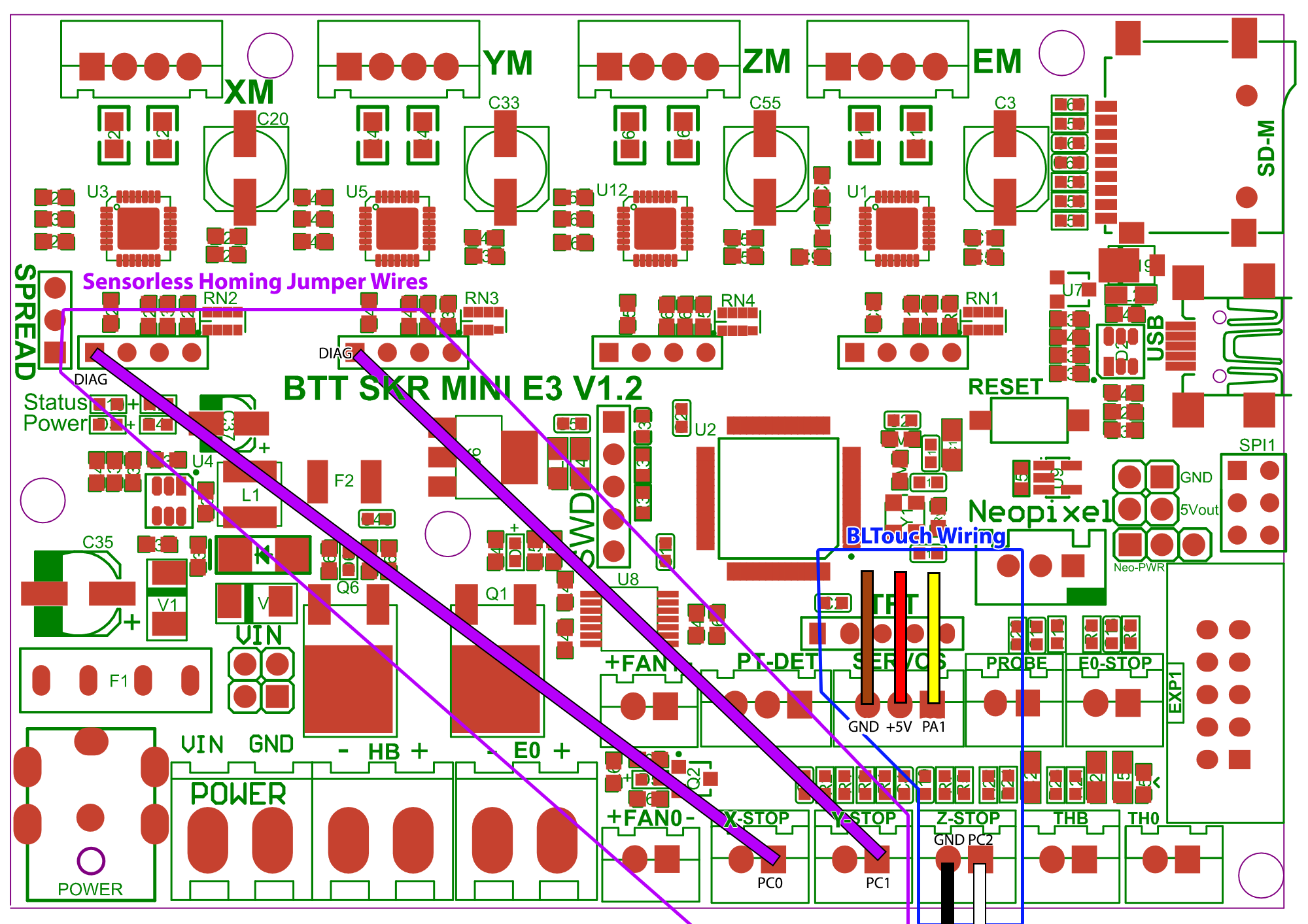
That may also have been responsible for the loud bang on sensorless homing; I was perhaps using too low a sensitivity value for the same reason. Now it’s just a moderate tap. (Actually, not sure; sometimes it’s a moderate tap and sometimes it has the classic “grinding against the end” lost step noise for a couple steps, even with the fixed settings. Maybe that means I should adjust it more?) I’ve really solved this by lowering the sensorless homing current to 200mA, which seems to work fine and also results in just a mild tap each time so far.

The PEI (if that is what it really is) sticks too well. I’m having trouble removing prints. Probably I’m printing at too high a temperature, using bed temperatures that might be appropriate for printing on glass. I’ll try turning that down. Looks like others have seen this; maybe I should try windex instead or in addition.

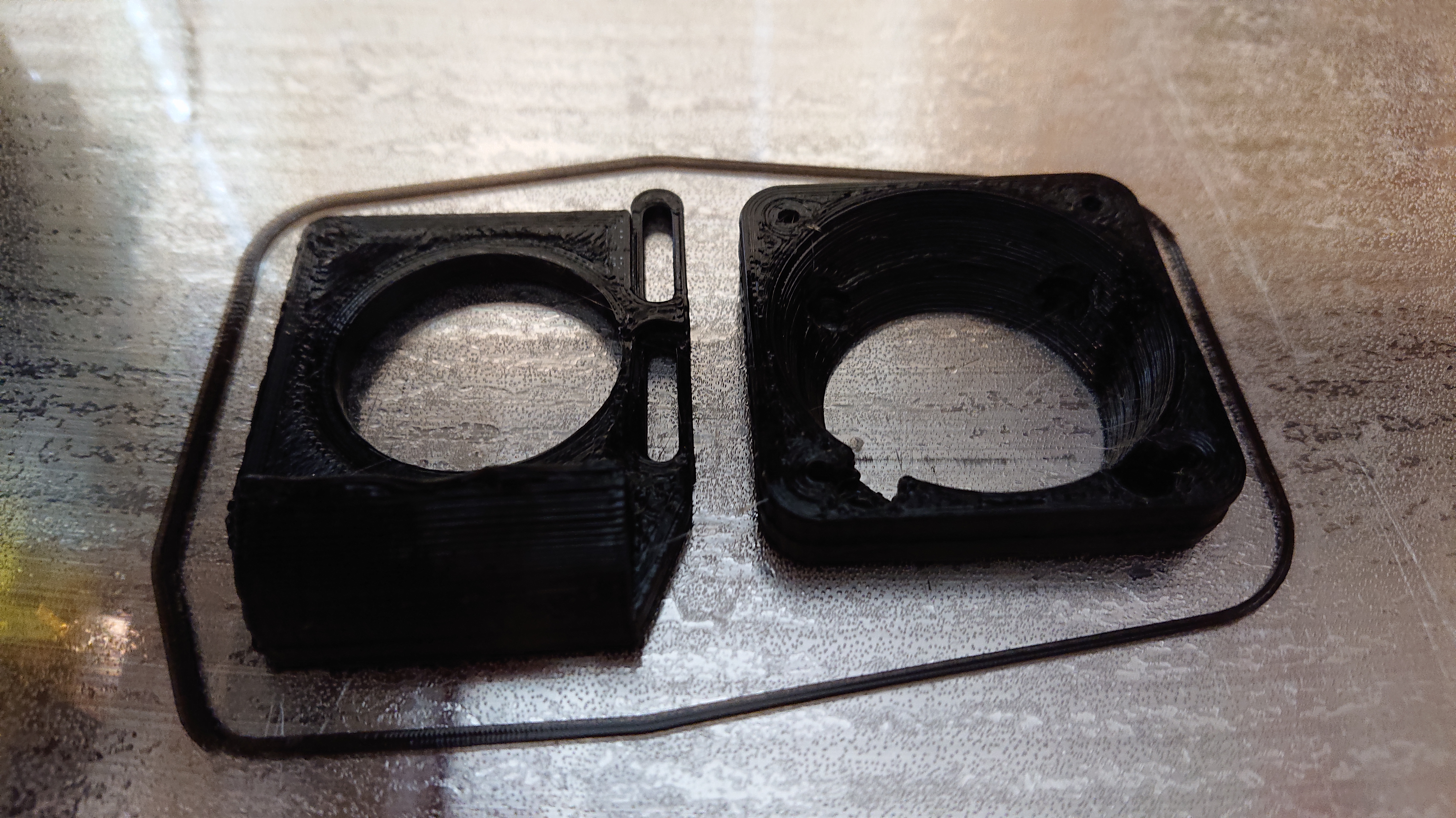
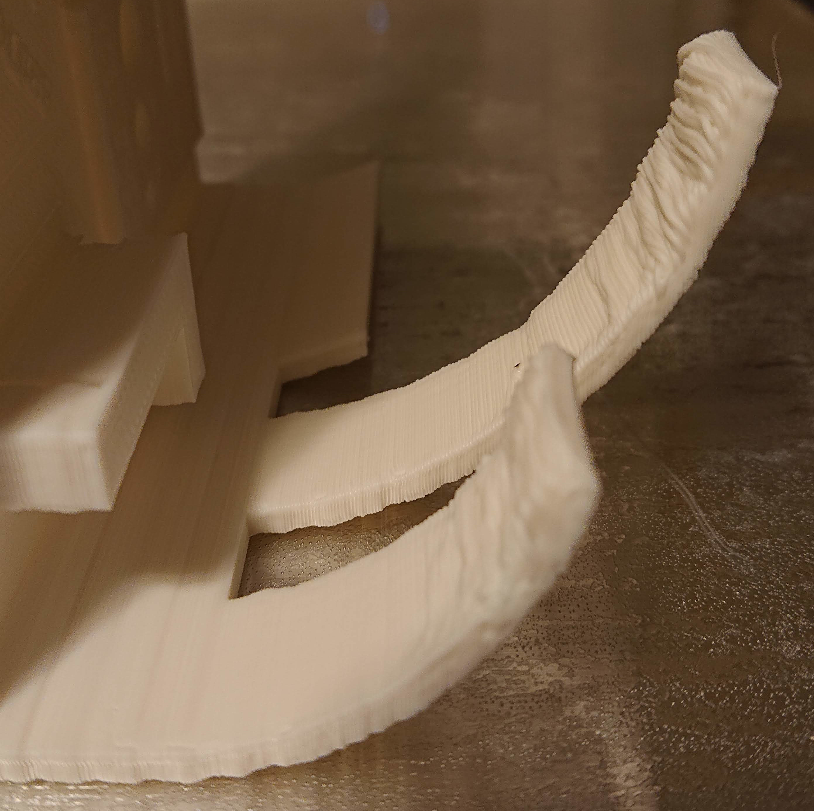
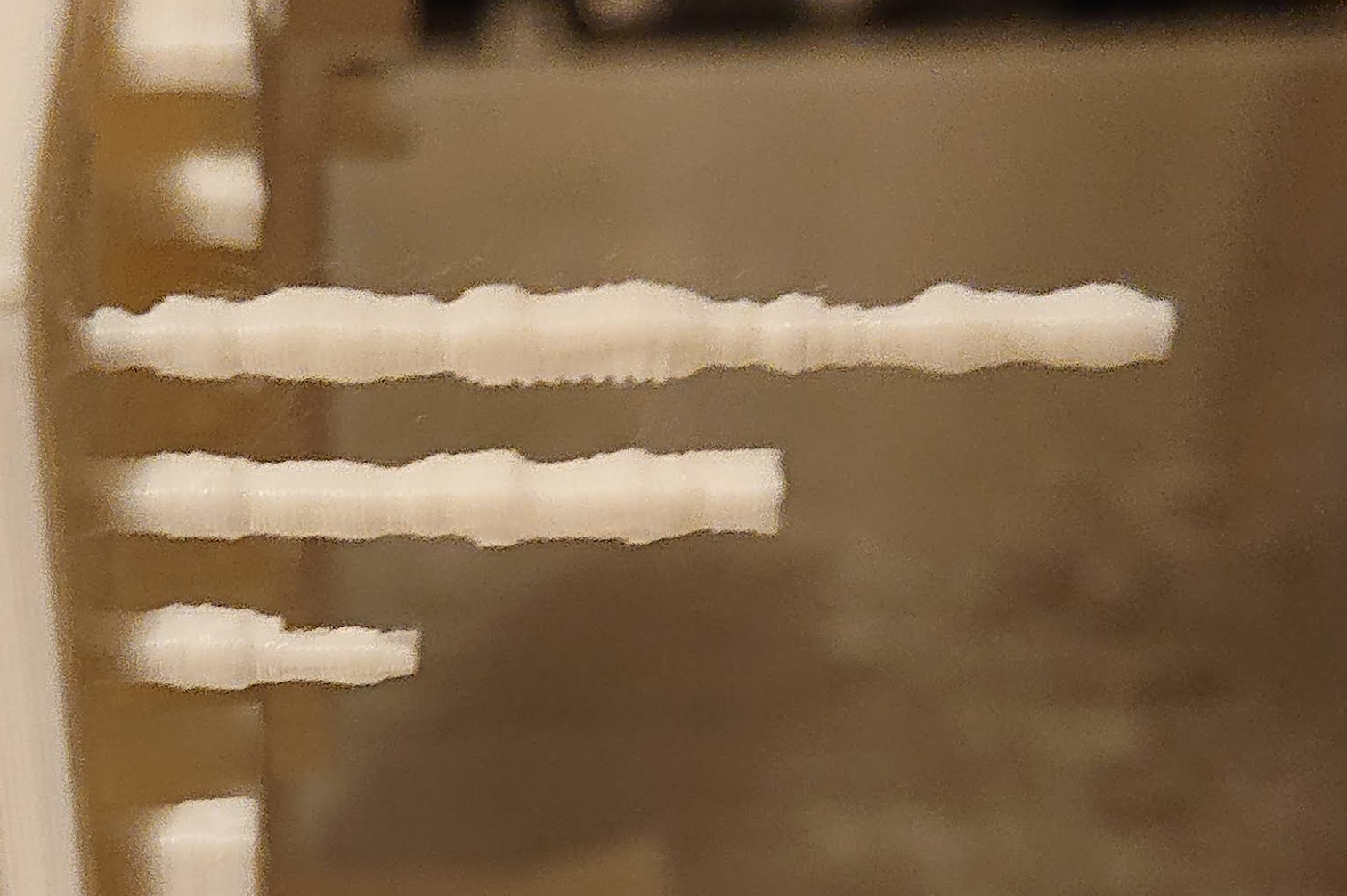
I changed my mind and am printing my 40mm fan adapter and shroud as my first upgrade before I design a new cooling fan duct; it needs it. …It turns out that the print cooling fan has a bridge of over 30mm and printing it hot for PETG (260⁰C) without a cooling fan it droops a little. (I re-formed it a little with my fingers after printing while it was still soft, so it should work.) But to print the cooling fan duct right, I need a cooling fan duct. :thinking:

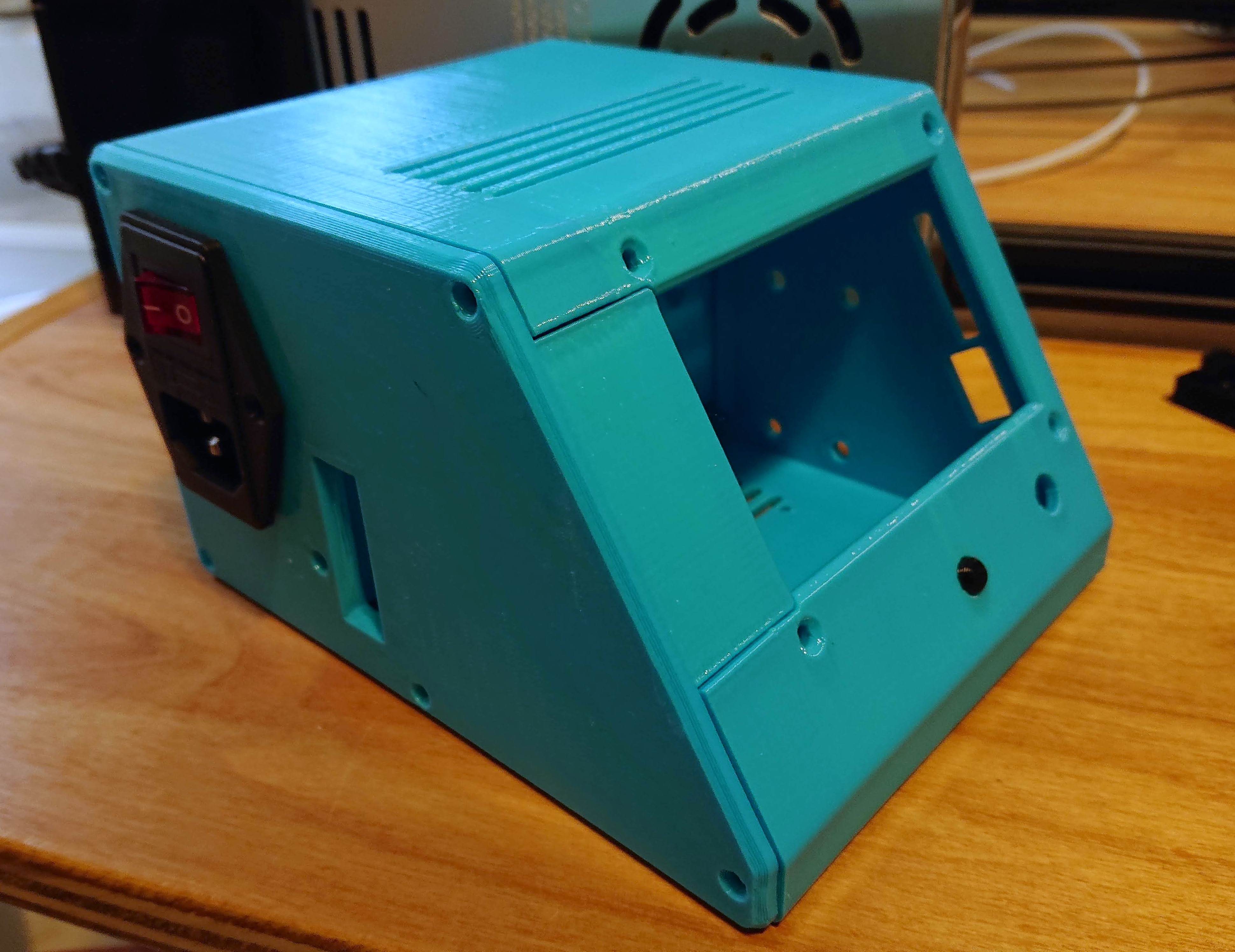
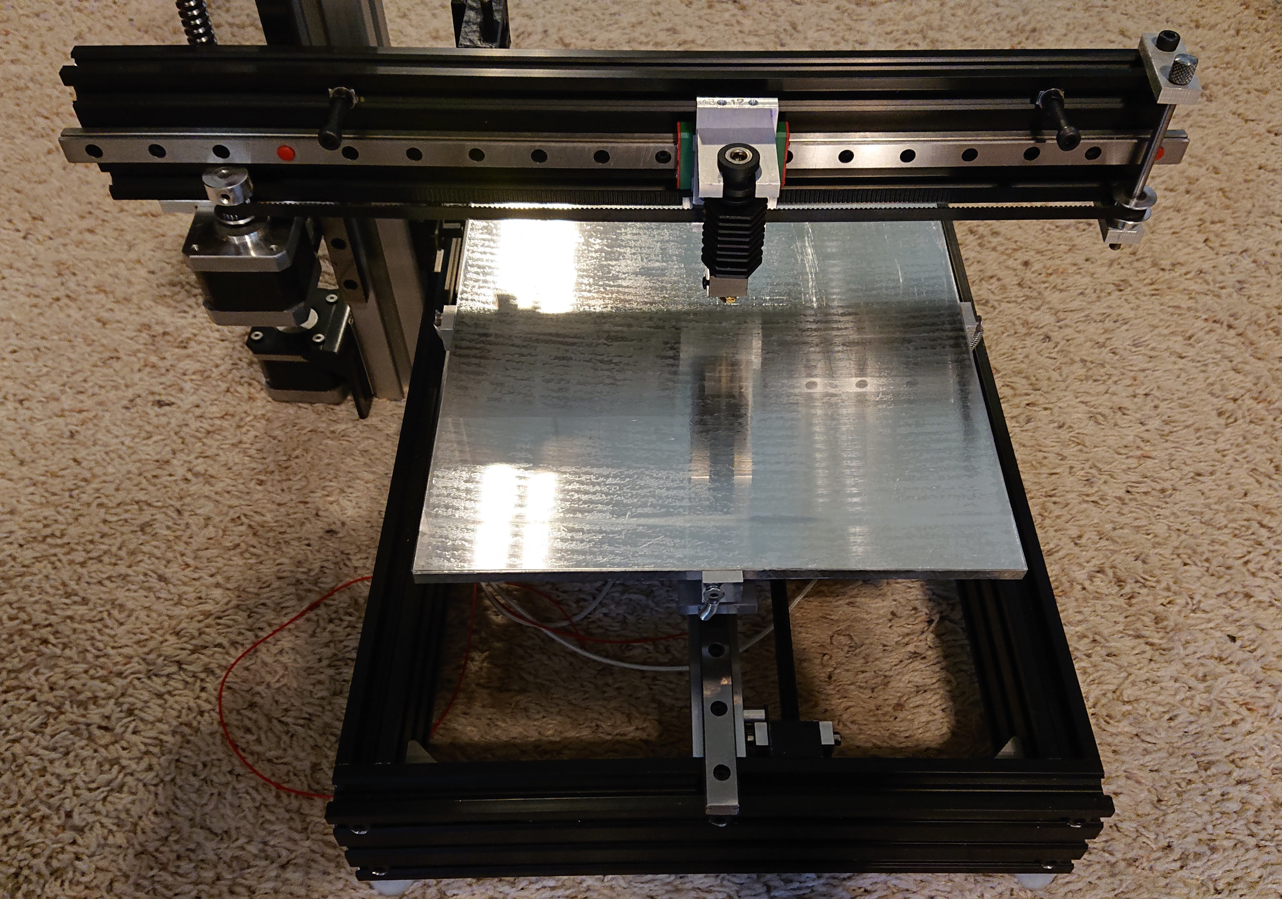
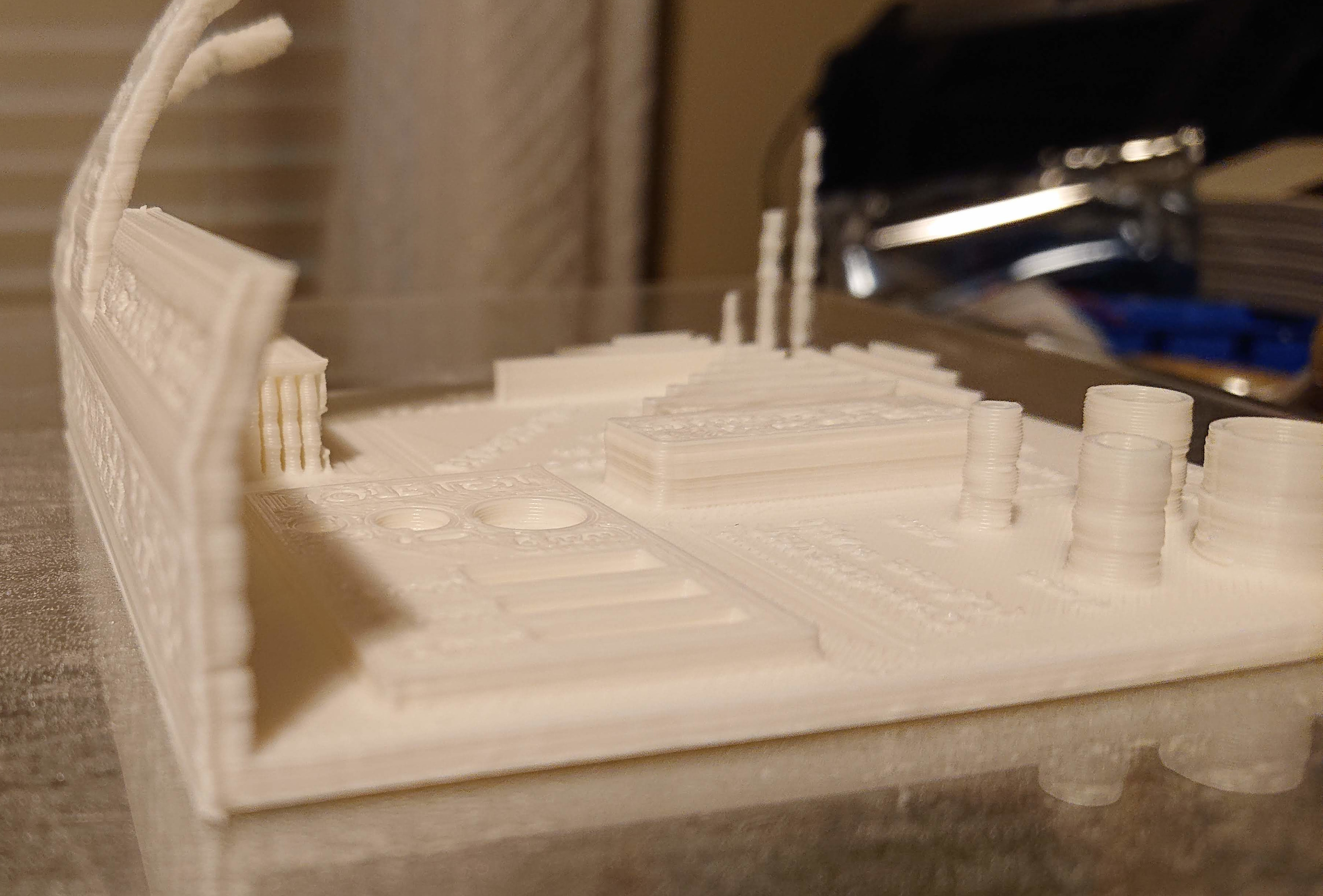
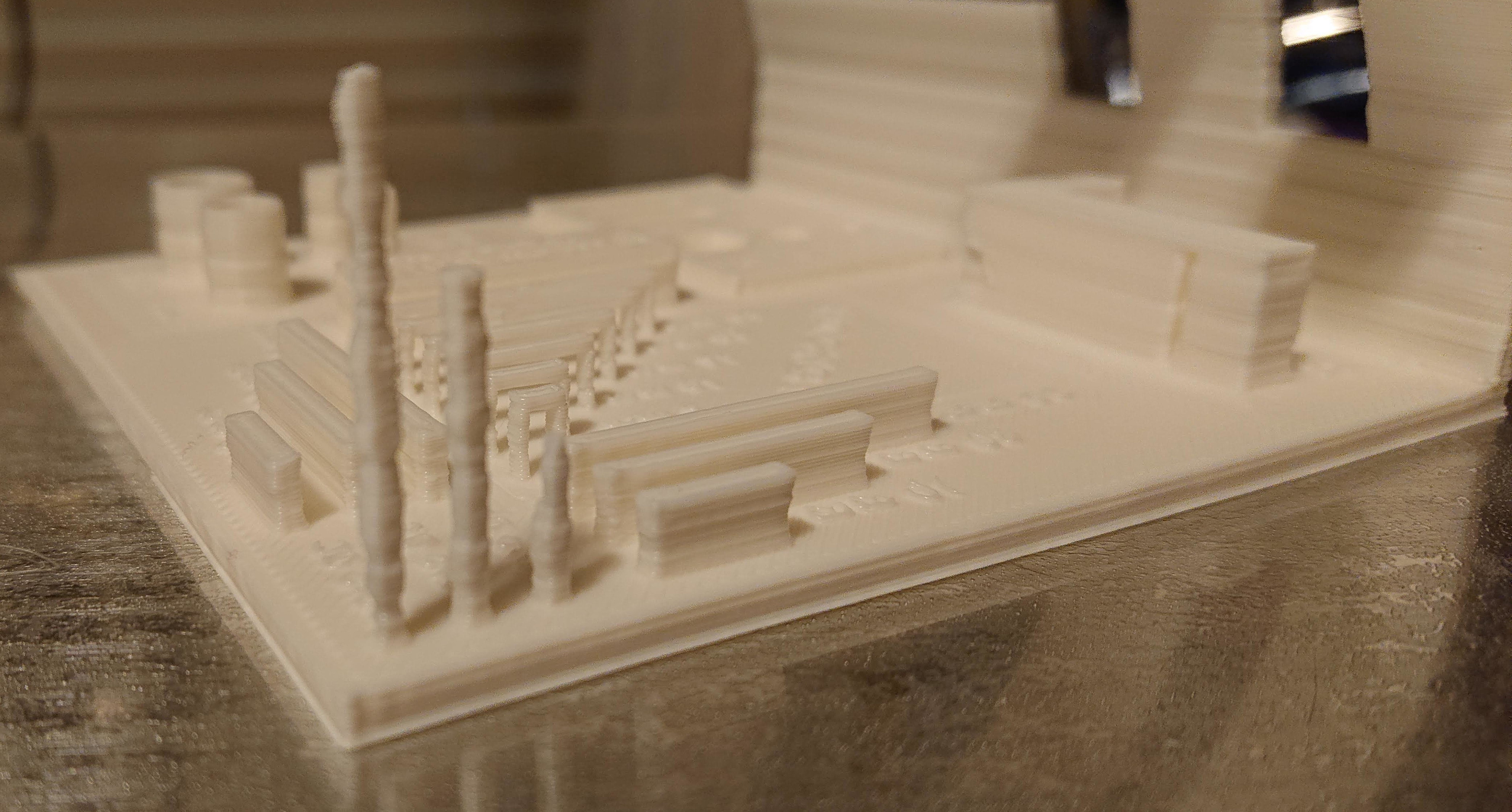
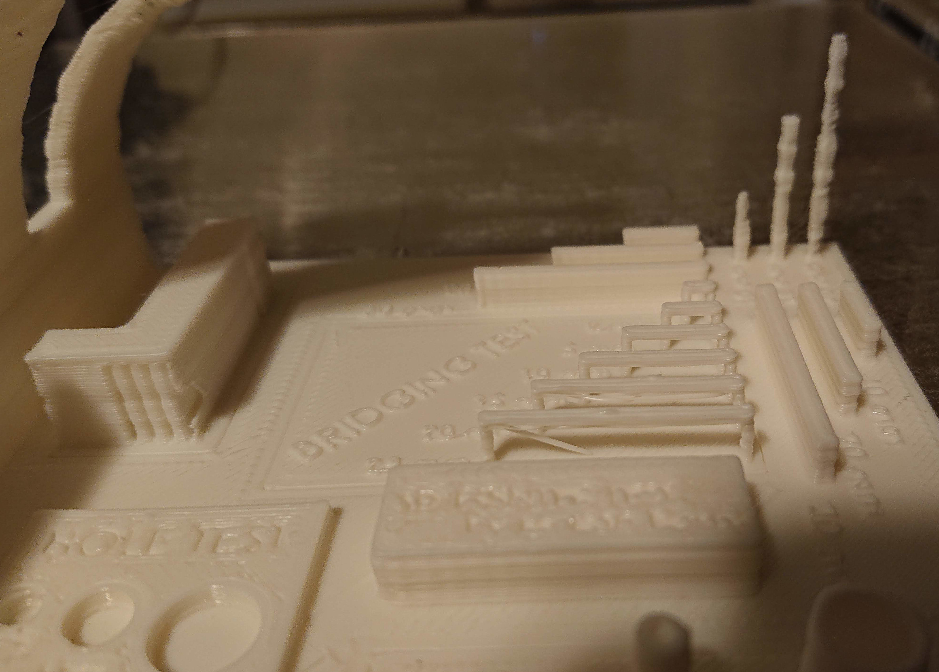
Here’s the first working print! The printer needs more work, but it’s in better shape than the old gantry printer it replaces.

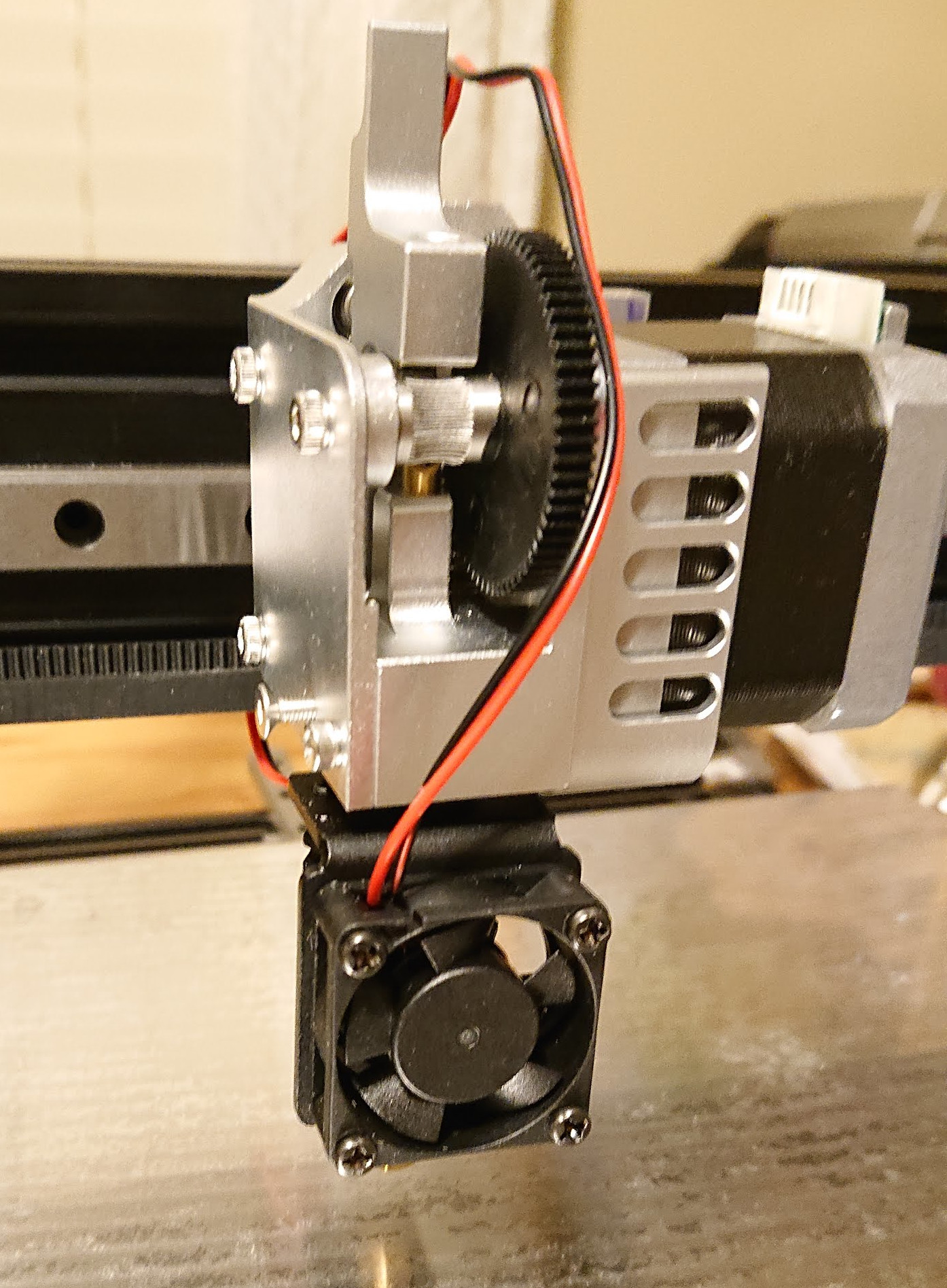
You can see that I still need to do a pid tune — after I put the fan shroud and cooling duct on and wrap the hot end in kapton tape.

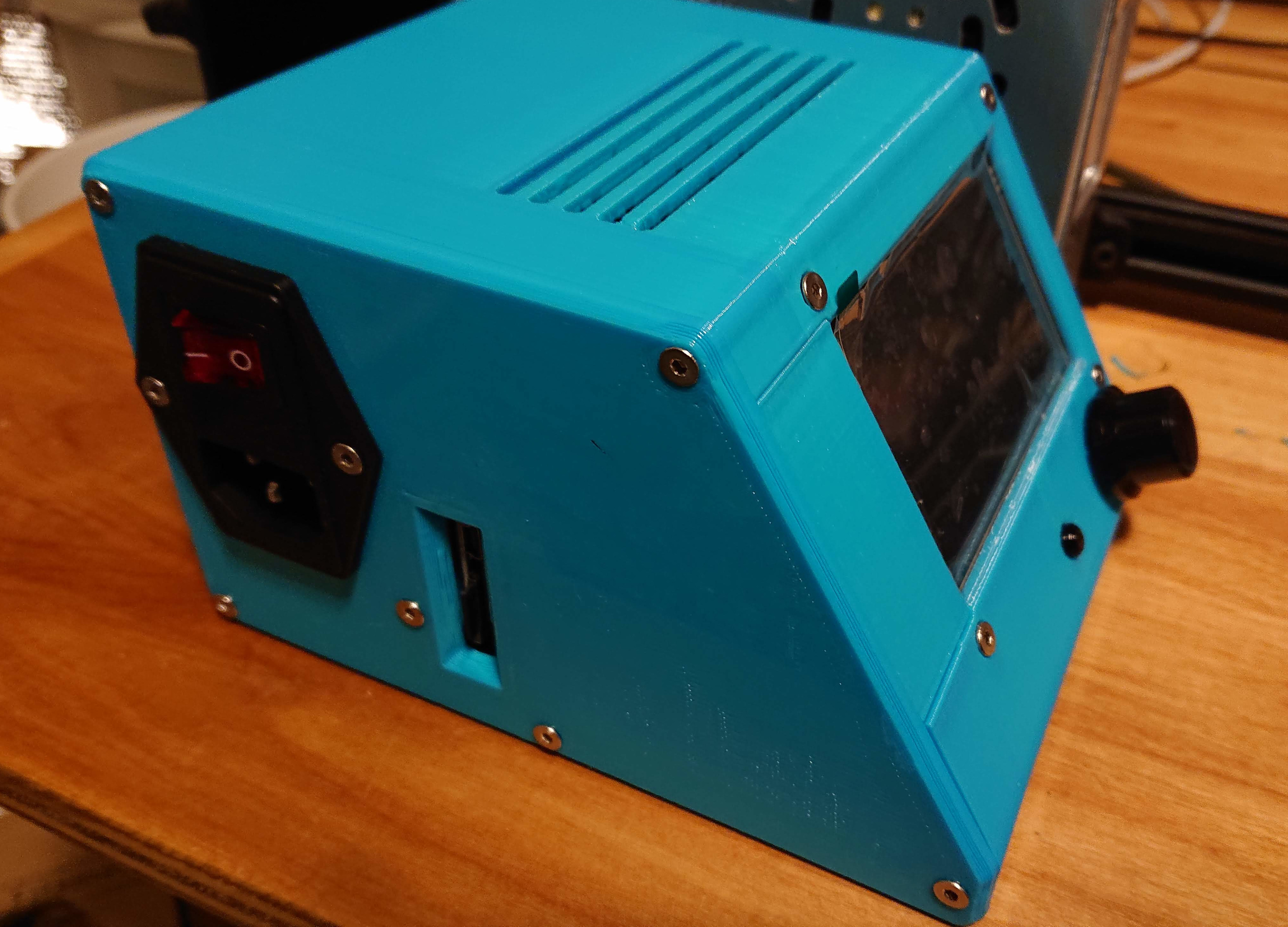
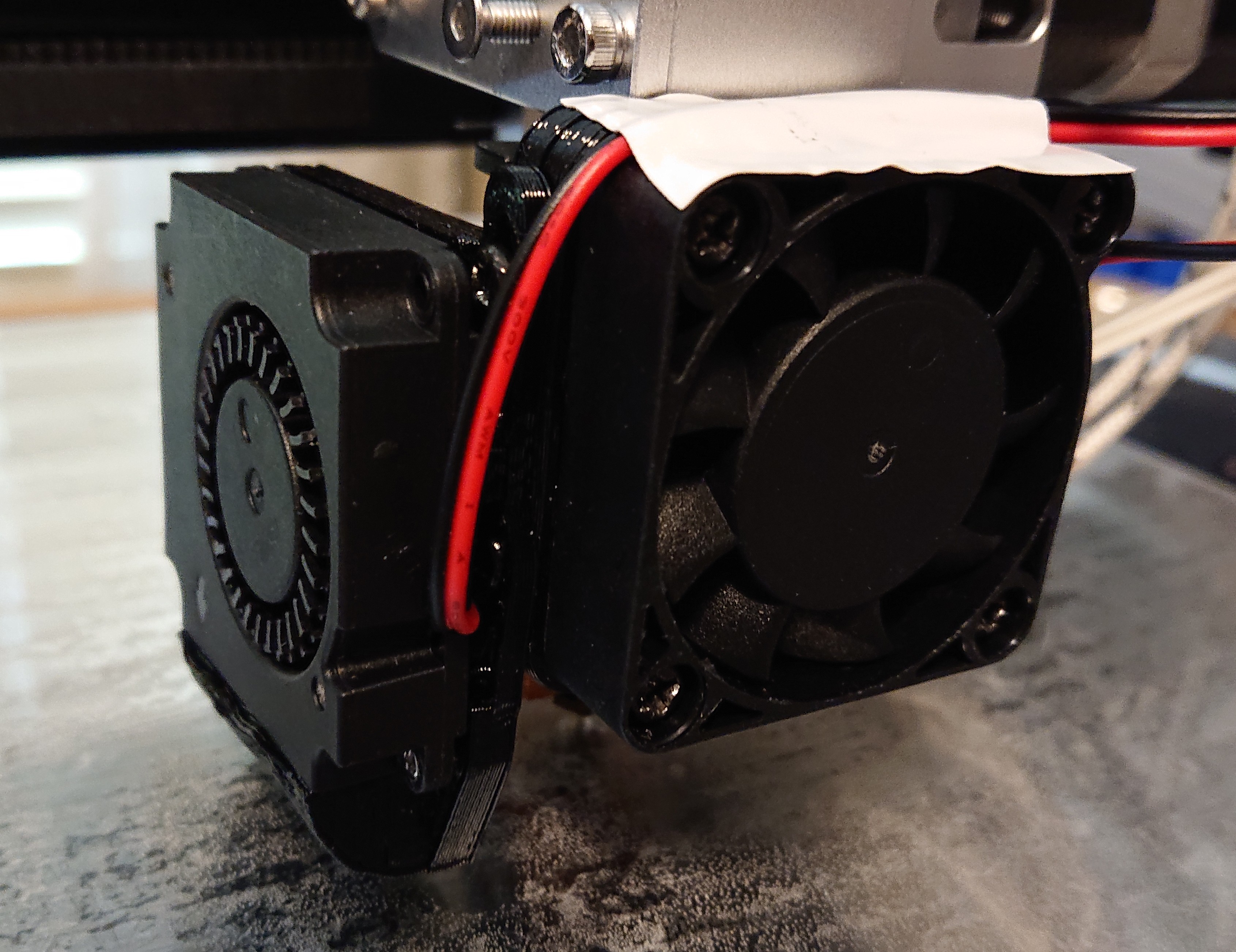
Here it is, mounted on the printer:

I wrapped the hot end heater block in four layers of kapton tape and used more kapton tape to make a shroud to keep air from the heat sink cooling fan away from the heater block.

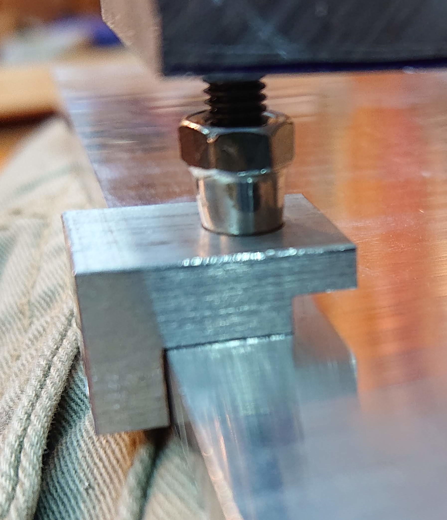
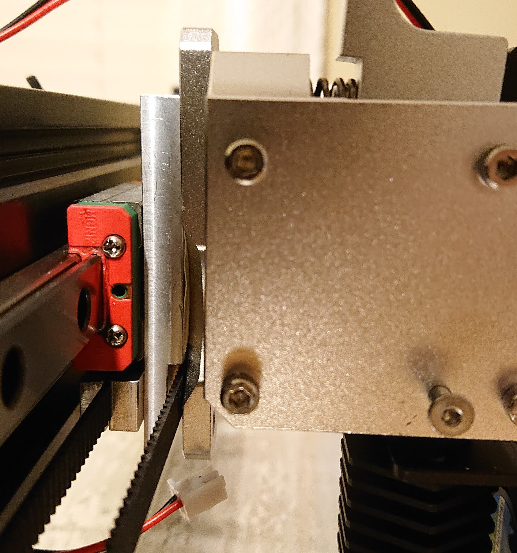
The hack for mounting the extruder isn’t quite steady enough. I think that instead of using the mounting plate that came with the extruder, I’ll make my own. I had already put a set of M3 holes 12mm apart on the top of that piece mounted on the block, and I have an idea for a slightly less hacky design that utilizes those holes for a steadier mount.

I’ve been measuring the temperature of the bed. I have a 200mm x 200mm heater centered under my 224mm x 274mm bed, which isn’t obviously optimal. Once the bed reaches steady state, though, there’s only 2⁰C difference between the center and the edge. That’s better than I expected. Given that, especially for a printer that is rarely used to print footprints substantially exceeding 200x200mm, I think I’ll count this as a win.

I haven’t figured out where to put drag chain yet to make the wires look neater. Right now, I have some of them (bed heater/thermistor, all wires to the extruder) wrapped up, but that’s it; I have rather a tangle of wires at the side, which makes the case look less beautiful. I’m so happy about printing, though, that I’m not in a rush to fix what ain’t broke. For now, I just used some cable ties to hold wires more neatly bundled together. The ugliest thing is the X stepper cable hanging loose off to the left of the printer.

Print volume is 224 X 274 Y 290 Z — bigger than makes much sense for a bed-flinger printer.

2 Likes

I got so excited about printing, I forgot to PID tune. The hot end and extruder are the same as the corexy and so its settings are probably fine, but the bed has more power per area and so the values it inherited from the corexy are most likely not optimal.

I woke up this morning to the results of a 2h50m overnight print of an all in one 3d printer test. I’m hoping that wrong PID parameters are what is responsible for these banding artifacts:


Bridging looks perfect to 25mm. I should increase at least bridging speed.

Set on the side to show the overhang tests more clearly:

The fact that the banding looks different on the 10/20/30 mm towers from the side gives me hope that this is a thermal problem, not a mechanical problem:

I think I can probably speed up a lot. This is at a very conservative 60mm/s max print speed. At least, it’s conservative for the hotend, which is 24V 50W.

But I’ll change one thing at a time. PID tune and the same gcode first; speed up later…

That’s a substantial change. So, reason to hope that the print I’ve just started will be higher quality. I’ll see the results in about 3 hours!

diff --git a/Marlin/Configuration.h b/Marlin/Configuration.h
index 337949abc..3ba7376bc 100644
--- a/Marlin/Configuration.h
+++ b/Marlin/Configuration.h
@@ -489,9 +489,9 @@
   //#define DEFAULT_Ki 1.54
   //#define DEFAULT_Kd 76.55
   // M303 E0 C8 S250
-  #define DEFAULT_Kp 7.31
-  #define DEFAULT_Ki 0.31
-  #define DEFAULT_Kd 43.65
+  #define DEFAULT_Kp 13.37
+  #define DEFAULT_Ki 0.83
+  #define DEFAULT_Kd 54.14
 
 
 #endif // PIDTEMP
@@ -542,10 +542,10 @@
   //#define DEFAULT_bedKd 1675.16
 
   // FIND YOUR OWN: "M303 E-1 C8 S90" to run autotune on the bed at 90 degreesC for 8 cycles.
-  // This was: M303 E-1 C8 S70
-  #define DEFAULT_bedKp 41.36
-  #define DEFAULT_bedKi 7.48
-  #define DEFAULT_bedKd 152.51
+  // This was: M303 E-1 C8 S90
+  #define DEFAULT_bedKp 39.67
+  #define DEFAULT_bedKi 7.28
+  #define DEFAULT_bedKd 144.18
 
 #endif // PIDTEMPBED
1 Like