Yeah I’m never quite sure what to think about the downloads anymore either. I just try and put it up on as many places as possible and hope someone who can find the files useful will discover it. It seems like either things hit critical mass or they don’t. Sometimes they start slow and then really ramp up, but other times my designs don’t get much traction.
1 Like
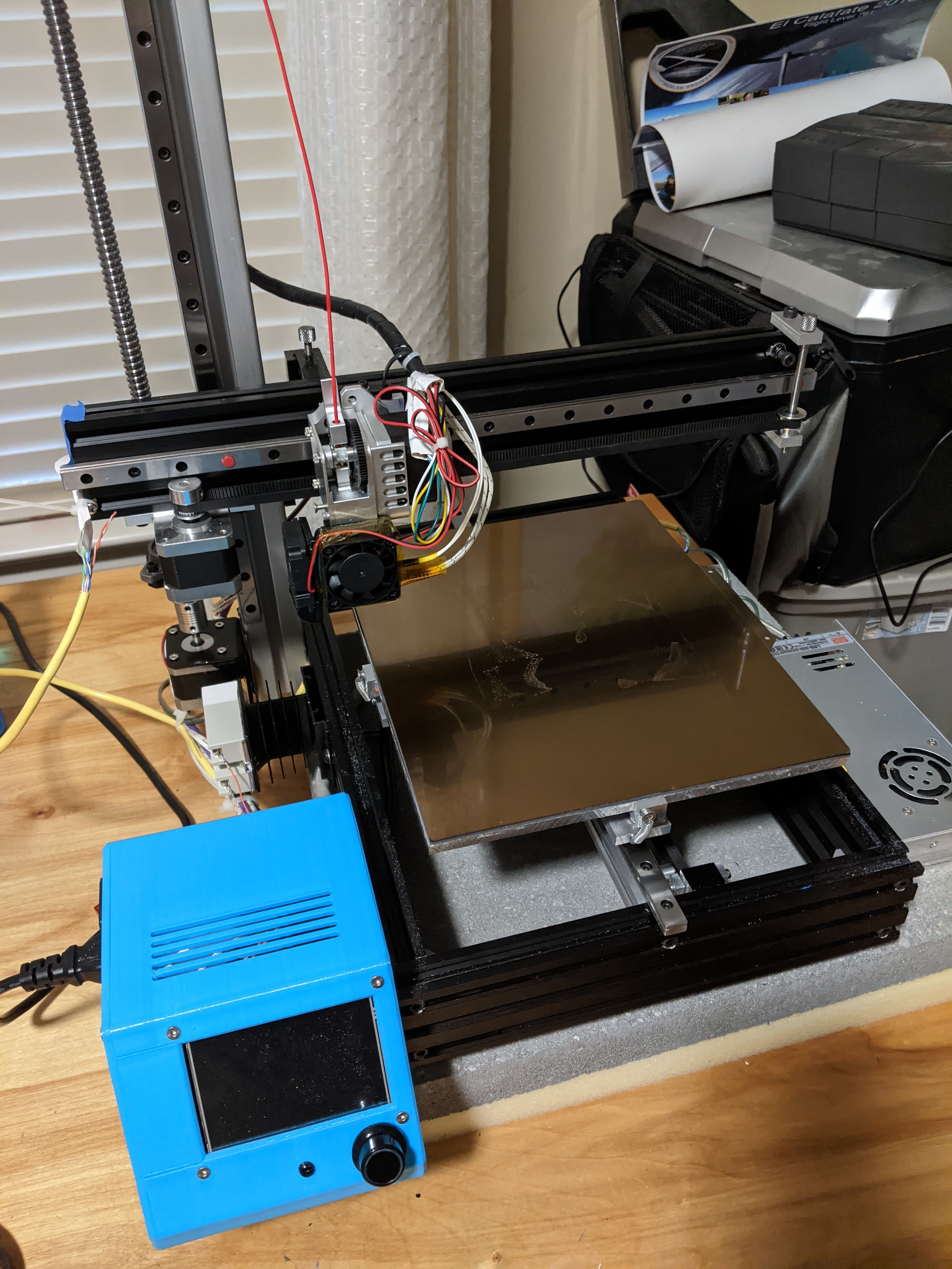
Printing on that terrible print surface was so terrible that this printer sat unused for months. I had just given up on that bed.
I finally ordered the same bed material that I bought for my corexy. For my odd 225mm x 275mm bed, they said it would be the same price as 235 mm x 235 mm — to just order the 235x235 and leave a note asking for 225x275 instead, and to tell them whether to put a tab on the long or short edge. As with my previous order, it arrived promptly (about 10 days total from click to door, I think) and in flawless shape.
I spent an hour or two painstakingly getting the junk “PEI” off the bed and then removing the adhesive. Took a few cups of acetone; I had to soak the top with acetone and then scrape up the adhesive, over and over. I finally got it clean and then installed the magnetic sheet.
I’ll have to re-do Z next, but now I’m expecting it to print approximately as well as the corexy. I hope. 
Also, the case now has about 60 downloads for each file on thingiverse and 121 total downloads on youmagine. It was also added to an Ender 3 collection on youmagine — not that it would actually be useful for the Ender 3 as far as I can tell.
3 Likes
Finally actually printing on this printer again!
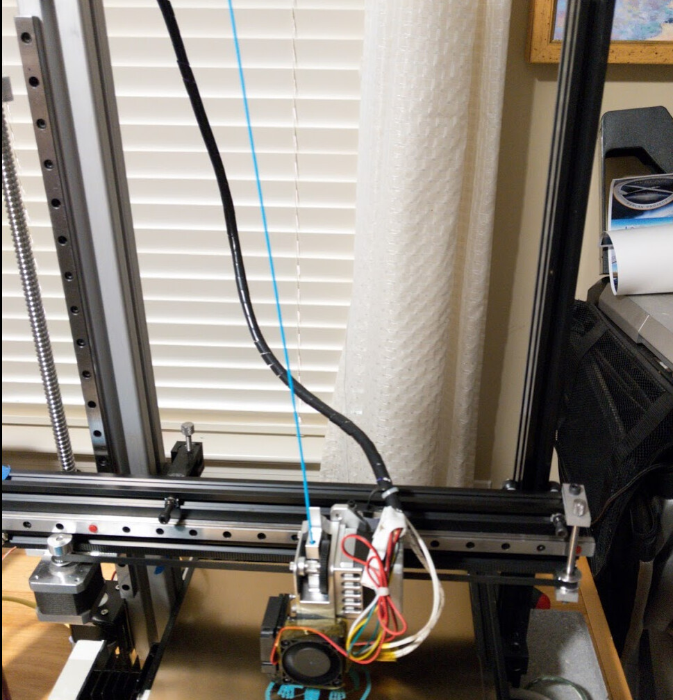
The cantilever arm does rattle a bit, and inertia from the bed moving back and forth does rattle the cantilever arm, which does affect print quality. The linear rail I used wasn’t very high quality. I’m trying to decide what the next step should be. I think my options are:
- Buy slightly better rail for Z — the Iverntech rail I put on the corexy seems pretty good, and I could just buy another one
- Put a tower of 2040 on the right side of the printer, and either:
- Get another linear rail and mount it on the right side tower, or
- Use openbuilds wheels on the right side engaged with the tower; a reversion to something like my original design.
I think that I could screw wheels into T-nuts in slots on the back of the cantilever arm as axles for wheels to ride up a 2040 tower. That’s a fairly easy and completely removeable quick hack that might help.
My youngest wanted me to put the printer on a concrete paver on foam, after watching a youtube video suggesting it, so we did that, but in retrospect I think it’s a bad idea and want to remove it. I think it makes the whole printer wobble back and forth and exacerbate the problem with the cantilevered arm. This isn’t a loud printer anyway. The trinamic drivers are quiet. The loudest thing is the power supply fan that comes on intermittently, and the cooling fan that I’m preparing to replace with a Noctua. So I think we solved a problem we didn’t have in the first place.
But even then, the second tower seems like a cheap thing to try, and only a minor distraction from Project Monocle.
1 Like
Yeah, you are using some heavier components than most cantilevered setups use (direct drive, heavy duty bed). I think gusseting, adding a second tower or lowering acceleration is probably in order.
Do you have pictures of the current configuration?
1 Like
There is very little play; I can feel it but not obviously see it, and I haven’t tried to measure it with an indicator.
I don’t think the direct drive is a substantial contributor; it’s only contributing inertia in a strong direction (up and down) with very little deflection opportunity. I think the bed shaking back and forth is probably the main source of the arm shaking back and forth. I have some 2040 and all necessary hardware sitting around so it’s an easy test to do. It was always an option, and in fact the first design wasn’t even cantilever at all.
It does have fairly low Y acceleration already, which I did precisely because of the mass of the bed moving back and forth.
1 Like
I had to do a few hacks. I used mini openbuilds wheels and a mini gantry plate. Then I realized that all the holes in it other than the axles holes were tapped M5, so I had to drill them out to 5mm. And the normal ¼" spacers weren’t enough to clear even button head screws, so I had to add 3mm spacers and switch the M5 axle screws from 25mm to 30mm. Then because the screw heads are inside the wheel axles they can’t be adjusted with the stabilizing tower installed, so it was trial and error until I got the plate screwed to the right place in the arm.
So it no longer looks like a cantilever printer, but it should work better.
2 Likes
Looks weird…
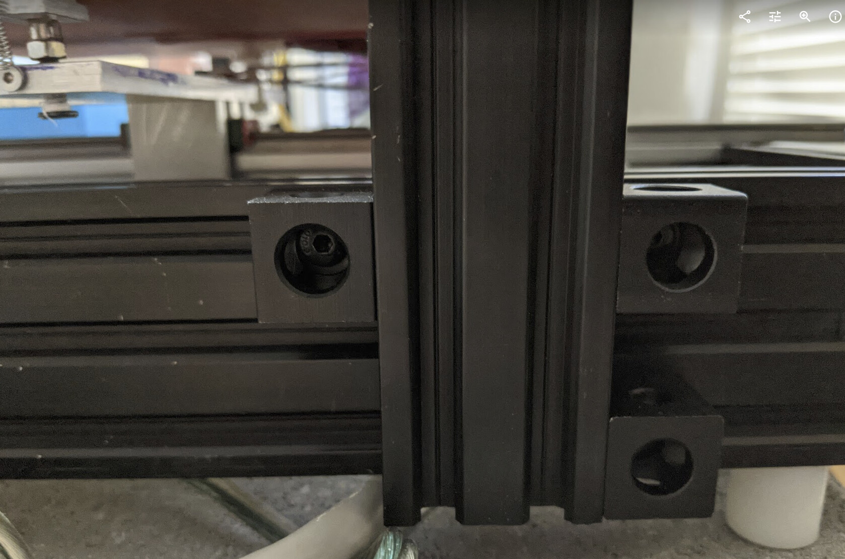
Here’s how the tower is attached:
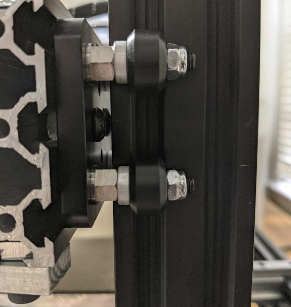
Showing the extra 3mm shims to accommodate the screw heads
This is clearly a make-do hack and moves this way beyond what makes sense for someone else to reproduce.
2 Likes
I am surprised you beefed up your X axis but kept your Y axis wimpy so the bed has more chance to tilt. If there is a reason for that, please excuse me for not reading everything in the discussion thread to find it. My eyesight is not correctly corrected and I am reading this from a tv used as a monitor and reading limited amounts to reduce eye strain.
In what sense is the Y axis “wimpy”?
What I did reduced unwanted movement of the X gantry in the Y dimension, essentially.
The bed is quite stable. It is balance on its linear rail block and doesn’t wobble or tilt. It’s sitting on a kinematic mount, so it can be tilted backward, but the spring at the pitch screw prevents that.
I think that I might still be seeing some slight binding in the Z screw as artifacts in the first cm or so of printed objects, but need to do more testing now that the printer is generally useful, which it wasn’t before I replaced the bed.
You only have one beam down the center to support the bed, right?
Yes.
Deflection of a cantilever grows as the cube of the arm length, which was why I went with 2060 for the cantilever arm. It’s still effectively a cantilever even with the stabilizer in place.
The 2020 supporting the Y linear rail is supported at both ends and the steel linear rail is also fixed to the top of the frame at both sides. It’s also shorter than the cantilever arm. The 2020 is not merely simply supported at both ends but also has fixed square ends resisting deflection. Similarly, the linear rail is not merely simply supported inside the ends but is screwed down to the flat surface of the 2060 frame. This is why I believe the 2020-supported bed has less vertical deflection than the 2060 cantilever arm.
I didn’t load up a full model to do FEA to support this napkin-level analysis. I did check some pre-calculated deflection amounts for cantilever and simply supported v-slot extrusion in 2020, 2040, and 2060 profiles (ignoring the linear rail component and additional stiffness from being fixed to the square 2060 frame) to make sure it would be sufficient in each case. Unless I recorded my findings above somewhere in the 150 posts of build log, I don’t have what I found, I just checked.
HTH!
1 Like
So you do not expect the bed to be unstable near min x and max x? Just to be sure we are on the same wavelength.
This is the sort of movement I am concerned with…but stuck sideways. It would of course look more accurate with a fixed width font.
<|
 |
 |
 |
X|
 |
 |
 |
 | >
I edited it to make it fixed width (mod thing…) by putting it between markers like this:
```
this is fixed width
```
Why would bed stability have anything to do with X movement above it?
I am not talking about the cantilever at all. I am thinking your bed will be able to tilt to one side.
The bed can tilt backward, if pushed against the spring at the front. That’s due to putting the yaw and roll kinematic mounts near the center instead of at the far end. That’s an optimization to reduce bed assembly mass. That was occasionally annoying when trying to remove prints before I got the magnetic bed, but is now a non-issue. In fact, I’ve thought about disassembling it and removing unneeded mass from the “frog” bed support to reduce inertia.
For play in the bed allowing it to roll side-to-side, in practice it’s simply not an issue.
What forces do you imagine tilting the bed side to side? It’s being held up by ¼" aluminum plate that is firmly screwed to a linear rail bearing block. And there are really no roll forces to speak of that would make it likely to roll. Even when I was pressing down with a spatula trying to remove prints from the old bed it didn’t budge; now that I’m not doing that it’s even less likely.
Having two rails and two bearing blocks (or more!) side by side would be an over constraint that would make it likely to bind. The better quality the linear rail, the more likely to bind, because the less slop to make up for the overconstraint. And it would be temperature-dependent — it might print fine at a lower temperature, and start binding at a higher temperature, for instance. This isn’t super high quality linear rail, but it’s good enough and there’s no discernible play in the bed.
I’m not over-finicky about exact constraint design — my extra tower wouldn’t be necessary if the hardware were perfect — but binding between parallel linear blocks can be a real problem. I had it on my corexy when my adjustment system was too tight. It’s real. And this design doesn’t invite that trouble; I’d recommend the single center rail to anyone trying this.
For anyone pondering a massive bed flinger for some reason, I’d think that going to larger rail rather than multiple small cheap rail would make more sense. MGN20, HGR20, HGR25, or even HGR30 rail would add lateral stability relative to the MGN12 I used in this design.
Does that make more sense?
I do not know much about linear rails and how they deal with twisting forces applied to them. The X is that linear rail. It was just a concern that the linear rail and the extrusion it is attached too would be able to twist and result in the left or right side of the bed tipping or raising. If you do not have that problem, good to hear it. If you do have a problem with bed adhesion on the left and/or right side, I would imagine it is from that. At any rate, I feel you now understand what my concern was. I only posted as much as I did to make sure you understood my concern.
Did you ever straighten out your Z issue?
At least high quality linear rail is very well constrained in that respect. There is a much larger twisting arm on the linear rail holding up the X cantilever gantry, and the movement I see isn’t from the linear rail rattling. Bed adhesion problems are much more likely here from variation in thickness or a poor job trammimg the bed. But to be further clear: There is no substantial twisting moment applied to the bed, so there doesn’t need to be much stiffness. The weight is well-balanced and doesn’t change substantially; only the weight of the print eventually changes, and that’s so small compared to the mass of the bed and changes so gradually that it just isn’t a meaningful factor.
I learned after building this that the way I set up my table on a linear rail is also commonly used as an upgrade for the Ender 3. Not a big surprise; it seems natural to me once you are familiar with what linear rail can do.
I at least mostly fixed the Z problems. I have printed only a couple items since the most recent changes, and one of them showed some artifacts that I don’t know whether they are from the model or from Z binding. I need to do some more calibration objects to find out.
But if I were to do this again, I would absolutely use single-start lead screw rather than the ball screw I had sitting around. The ball screw requires far more precise alignment than lead screw. If it turns out that I still have an alignment problem, I might address it by going back to the idea of belt drive for the Z screw.
1 Like
Mark Rehorst has written at length about using linear rail. He’s full of useful and detailed information. He strongly recommends real Hiwin linear rail; shopping ebay to find high-quality used rail. I think that it’s easier now than it used to be to get decent quality “chiwin” knockoff rail at hobbyist prices, so I haven’t haunted ebay for great prices on used hiwin and have instead gambled on knock-off rail. I was quite pleased with the Iverntech I most recently bought; it wasn’t the cheapest I could find at the time but it was reasonably priced and costs less now than it did then. (I bought it to replace the rails that ended up on the pandemic printer, which were cheaper ebay specials a few years ago.)
Haven’t been using this printer much because of the combination of print quality issues and having a fine corexy right next to it that is my go-to. But now I’m trying to get it set up for one of my kids to print on. I had him make his own calibration cubes (both 20mm and 30mm, with grooves, so we can measure differences and compare inner and outer measurements) and replaced the spiral coupling with a dual diaphragm coupling, also aligning the motor better with the ball screw.
I Kept thinking that I had bed temperature problems from not-quite-periodic pattern in the layers. Finally realized that the hot end was slightly loose in the extruder! Either one was too big, the other too small, or both, but there was play. I wrapped a strip of soda can aluminum around the throat of the hot end seat to remove the play and it printed much better.
Until it skipped steps in one direction while printing.
With my luck this is another stepper with bad bearings.
3 Likes
With my Delts I would often just grab the hotend, while cold, and move the machine around to feel for any play. With 3D printed Effector and Traxxas Heim joints I would feel a bit of play every now and then and have to tighten the hotend clamp or tighten/snug all of the 12 screws at the heim joints(4 per side). I don’t do that with my Cartesians but really should. It’s also a good time to look a the belts at the motor gears and see if there’s any visible flexing.
If it’s been sitting, check if any of the belts have an odd spot in them from sitting wrapped around the gear for a long time and especially dust on the linear rails/bearings. Could be bearings but when things sit for a while, stuff settles and movement might not be smooth everywhere.
2 Likes