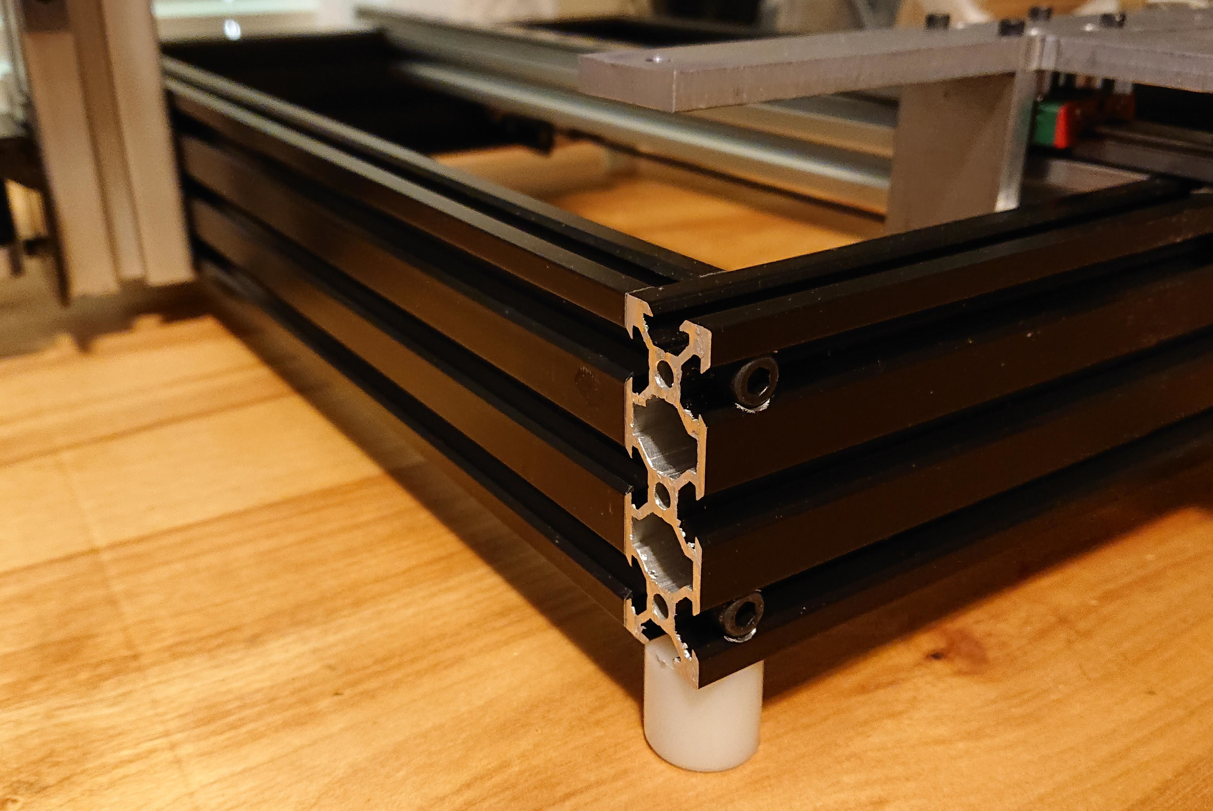
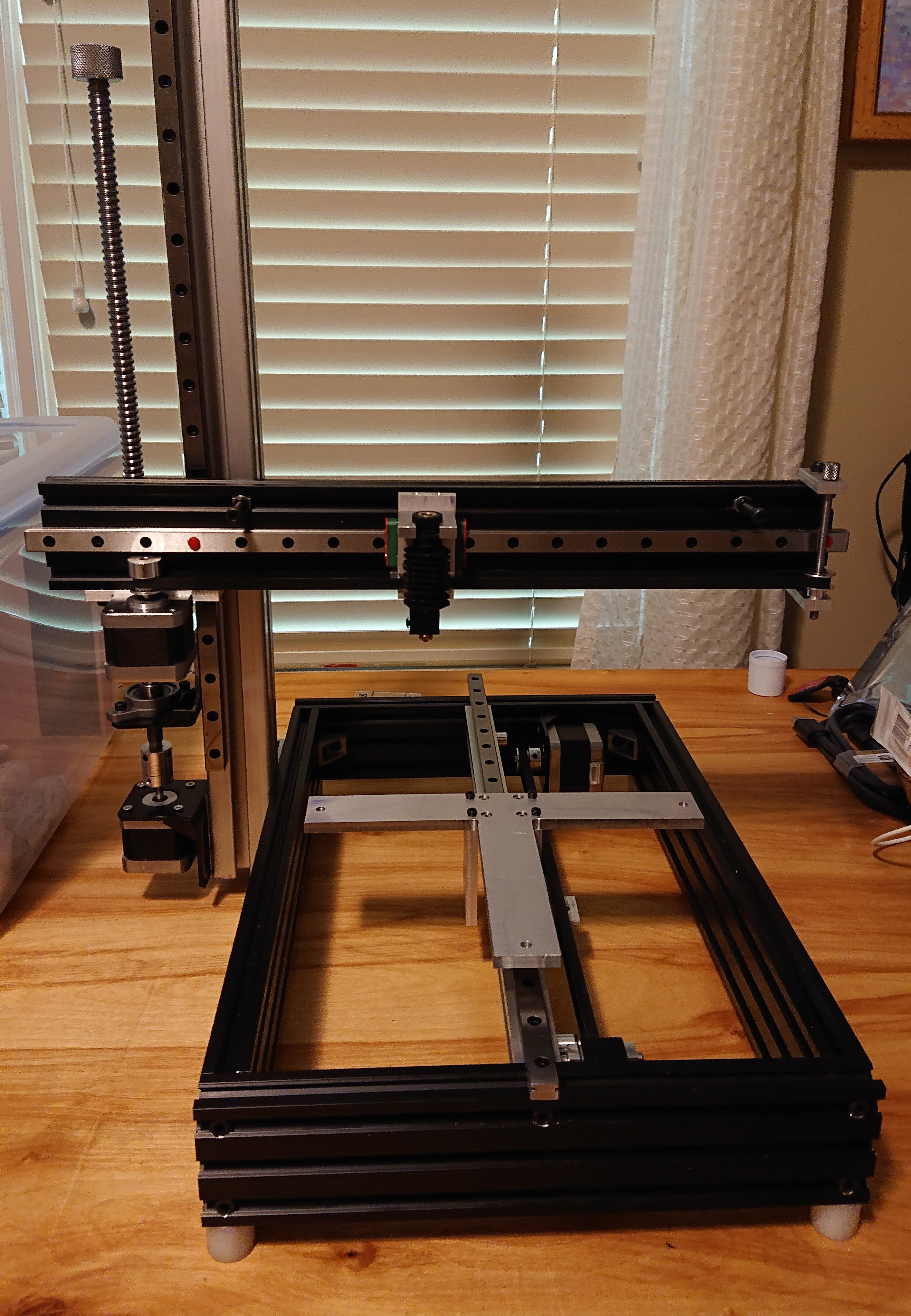
Yeah, the frame is 2060 extrusion mounted on 20mm feet (which will soon have another 4mm or so of TPU under them, in a few hours after my marathon print of fittings for the enclosure for the corexy printer finishes, which will be the tallest print I’ve ever made).
There weren’t pictures earlier; I am so ashamed of my disaster of a shop, where I am halfway through so many projects that I sometimes can’t find the tool I’m looking for, that I couldn’t bring myself to take pictures of the work I was doing in there. I back-filled pictures last night. 
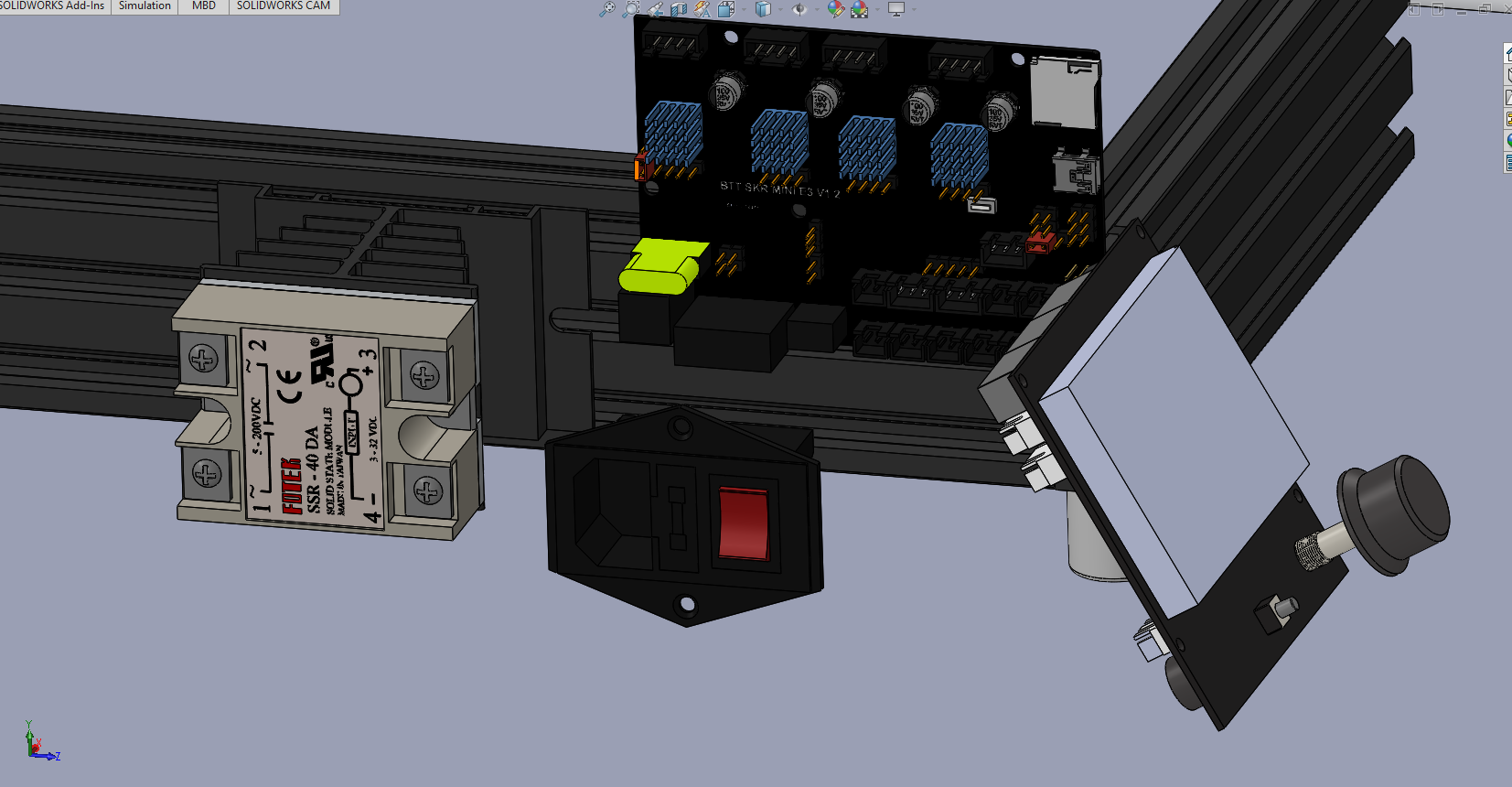
I finally got far enough in SolidWorks this morning, after hooking up my space mouse to that computer, to find the actual part (rather than an assembly into which it was linked), remove the smaller display, import the model of the TFT35, and start to try to figure out how to re-link constraints to the features of that model. (Got far enough to think that if I could just take a week or so to get past the initial ramp of the learning curve, I’d probably enjoy using SolidWorks enough to get over needing to run Windows to do so.)
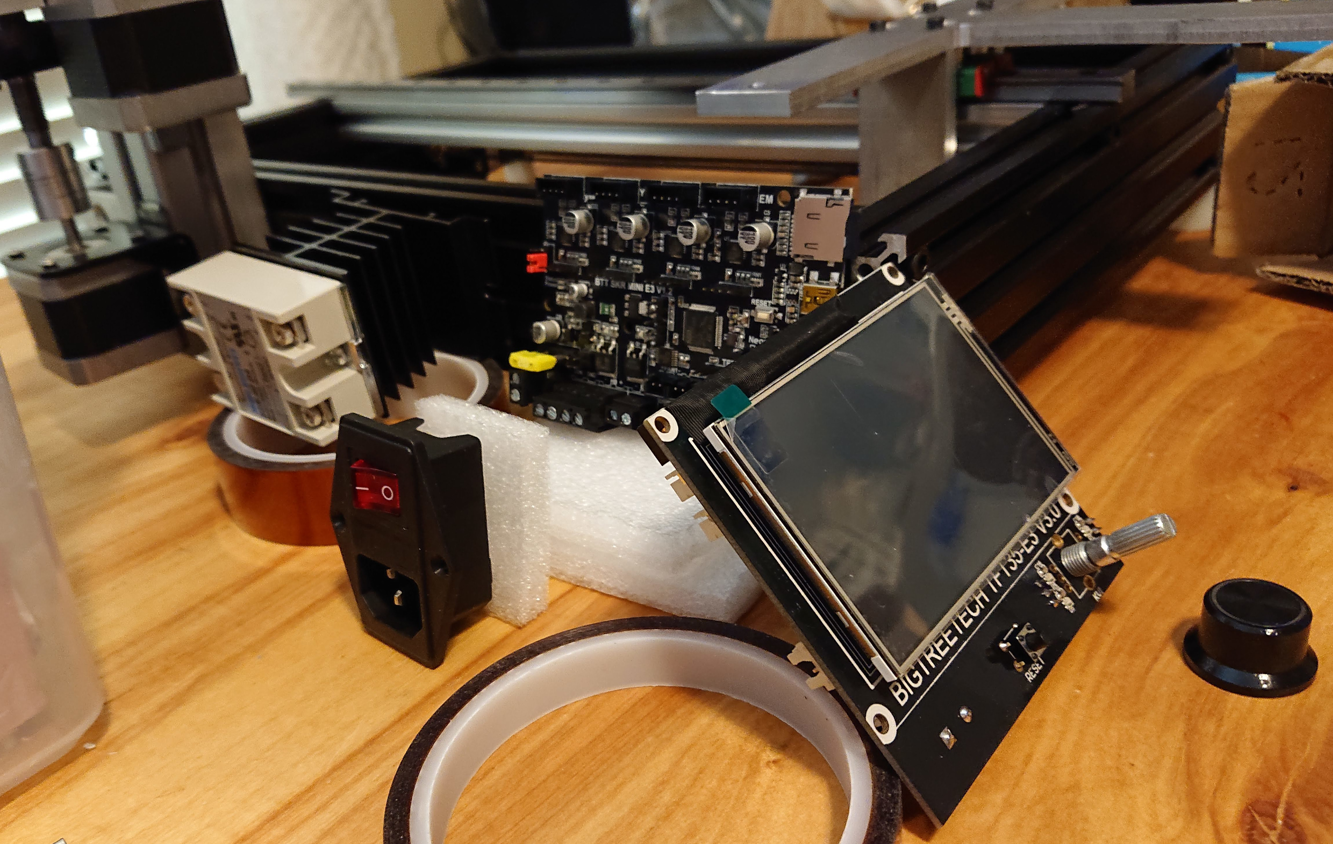
Then I looked again at the display I have and discovered that it isn’t the part that was modeled. What I have is the TFT35-E3 V3.0 which, I think, re-packaged up the TFT35 in a form factor that is an exact replacement for the Ender 3 display board. The dimensions are on github but I don’t know of a 3D model for it. They have a 3D PDF but not quite clear to me how useful that would be; Linux support for that seems to be slim pickin’s…
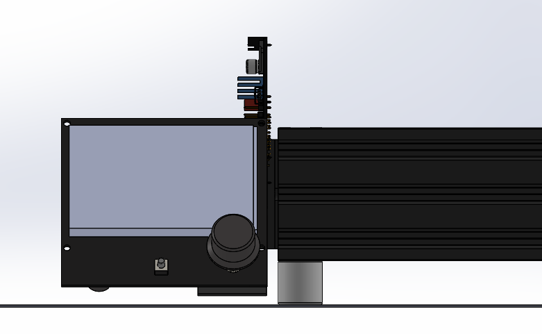
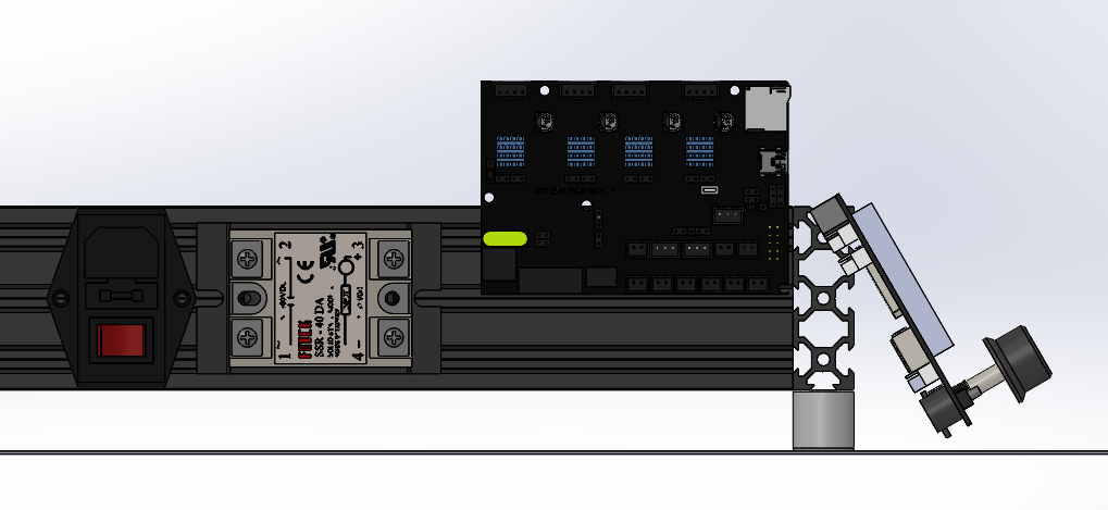
I was thinking of an arrangement that exposes the microsd card and micro-USB slot in the mini-e3, because on-board SD has lowest potential for print artifacts, and the USB port is useful, with the board set vertically for better thermal management. I want to put the 24V power supply remote under the desk to reduce noise from the fan, but make the mains power switch accessible. I need 120VAC to feed the heated bed from the SSR anyway. I like having the screen right out front, easy to get to, and I have plenty of desk space for it.
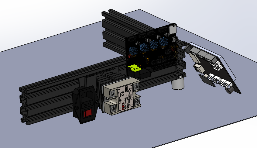
I’m attaching pictures here roughly mocking up the layout that I have in mind:
This doesn’t show the mini-e3 board as high as I would make it actually sit in order to have access to the USB port. There is plenty of room between the frame and the bed, so the case can stick up above the frame without a problem. (I just ran out of pieces of foam nearby to prop it up.  )
)
The AC inlet could be on its side with the C19 receptacle toward the back, instead of oriented vertically. That would probably make more sense than the mockup.
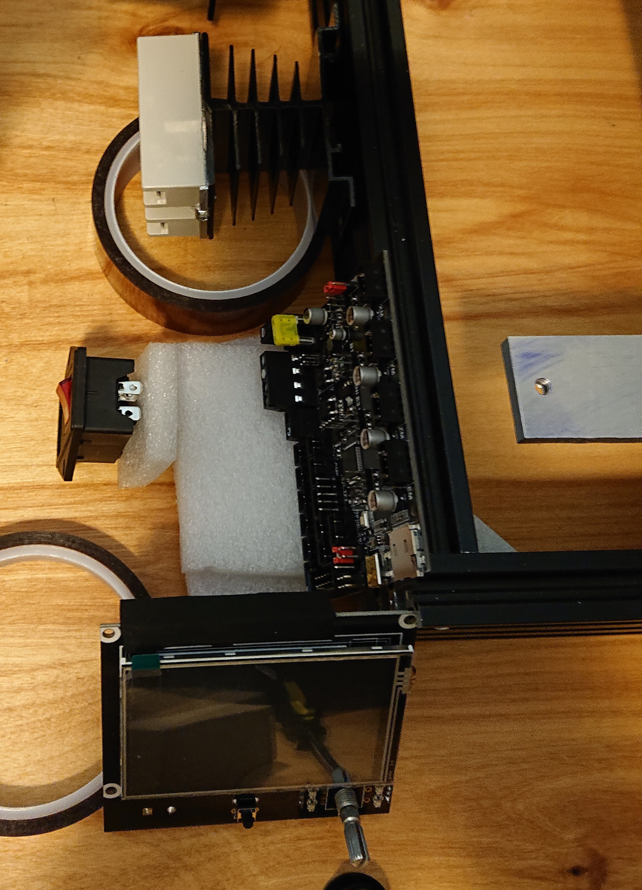
Here’s a top view:
Thank you!