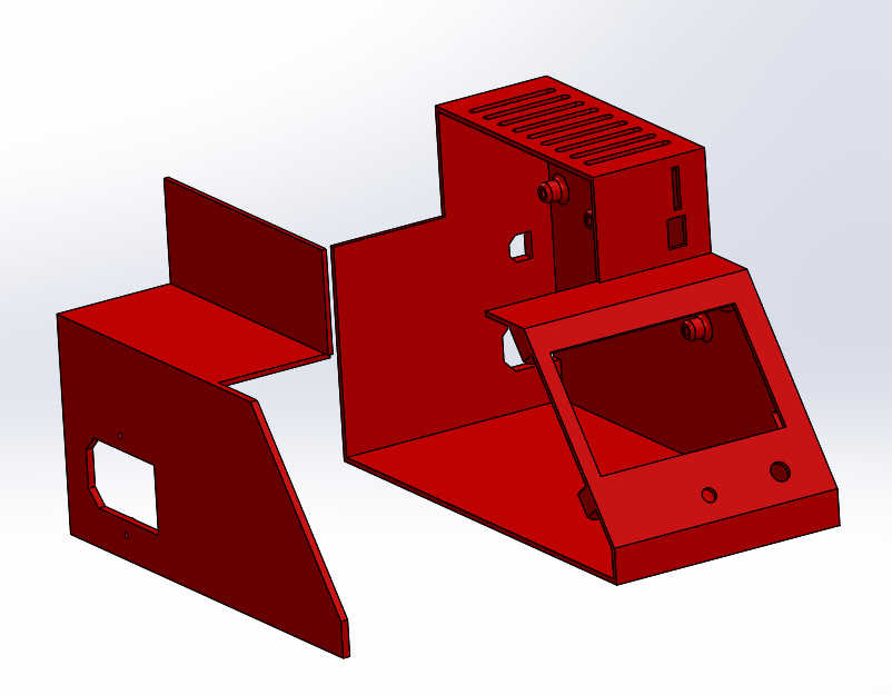
Preliminary layout and positioning. If the component placement and general shape looks good I can start to pretty it up (Curves/ Chamfers ), and figure out the best way to break up the panels for printability / strength / assembly / serviceability).
1 Like
That’s beautiful!
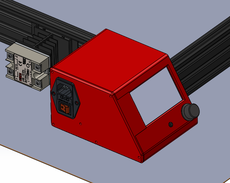
I will want to put slots in the lower part somewhere for airflow in, with ability to screw a 40mm fan inside it to pull air in if needed. I’d think that slots in the bottom 15mm at the back (below where it meets the frame) and a fan grill forward of the power switch; there’s room inside to mount a fan there.
I found the introductory tutorials in SolidWorks and started running through them last night. Knowing where the most common controls live and how to use them will be very helpful.
I don’t know whether the EAA Academic license I’m using for this (I’m definitely not doing anything commercial, so this is OK) allows me to install older versions in parallel to enable us to interoperate with the same native files. I should find out about that.
Before putting in more effort, though, let me play with another arrangement that might be easier to make printable. It’s fun to be able to think these things through!
1 Like
Are you on 2019? If so I can just swap over to my work PC.
With some ideas I have for how to cut up the current configuration it should be able to be printed entirely without support.
Yup! Installled for the first time a few months ago. ![]()
I just uploaded SLDASM and x_t files for a new arrangement that should be smaller, lighter, and easier to print. I think it might be easier to break out to print.
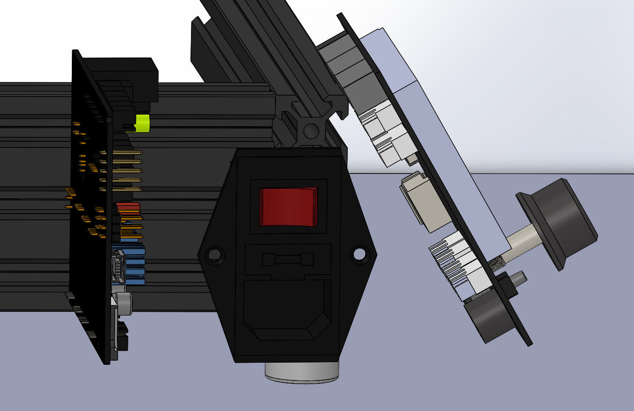
Yep I can work on an orientation based on that too. What do you want to do about routing of the AC away from the board and USB?
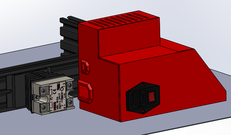
Could switch the AC to come in in a compartment behind the board and route backwards maybe. Just flip the placement of the two front to back.
I had something like that in a previous attempt, before but it was before I rotated the board 180⁰ in X. So yeah, that would make a lot of sense. Just want to leave enough room for a 40mm fan underneath. 
Yeah, this is better. It showed that it made sense to raise the control board to be top-aligned with the display board, and route DC cables underneath it. With enough room for cable routing, there is also room for a fan at the bottom, which would now be aligned with the bottom of the 2060, so plenty of airflow underneath. And it would open up the back for the cable routing holes you had originally modeled.
(This is sure fun!)
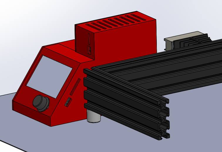
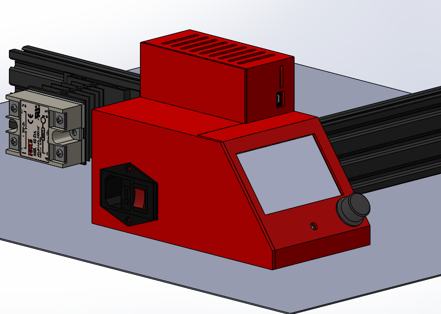
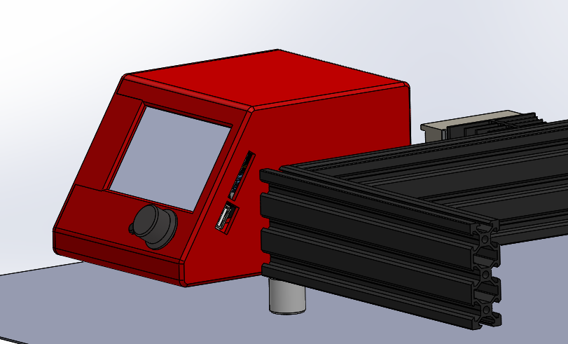
I note that this redesign makes this much more generally usable for random other people, since it just attaches to the side of probably a high percentage of vslot frame printers where the bed doesn’t extend over the side.
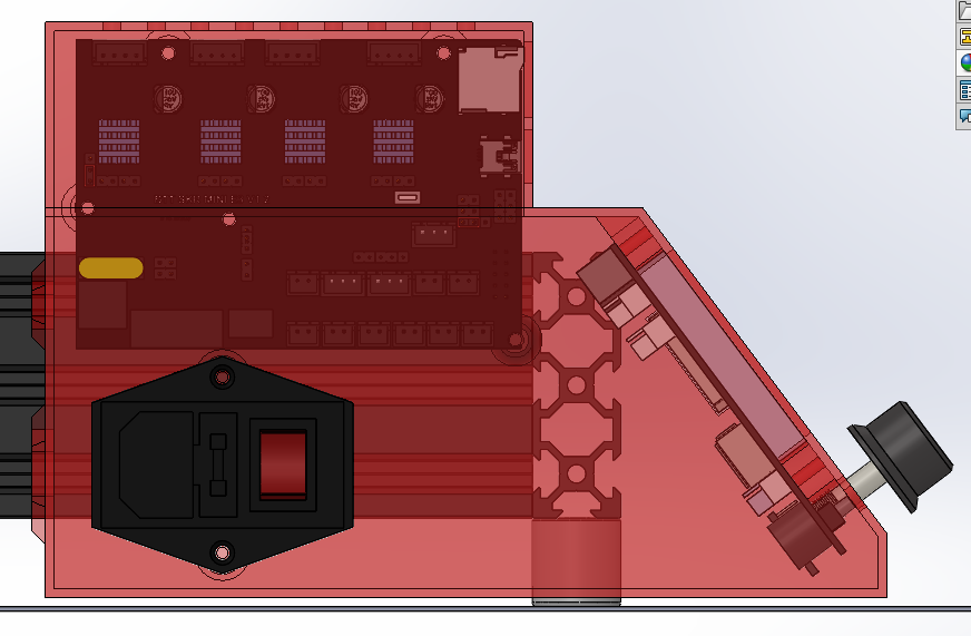
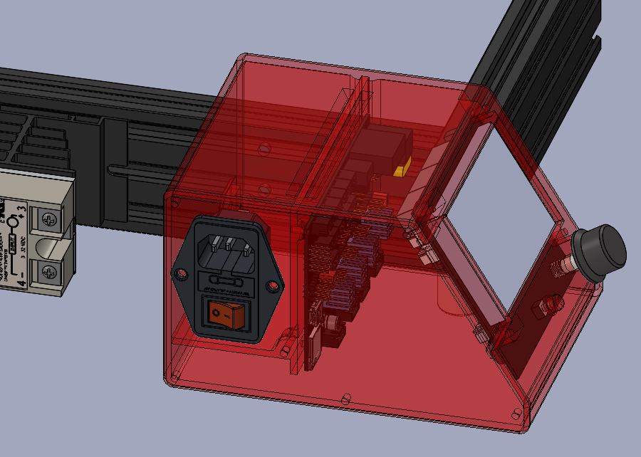
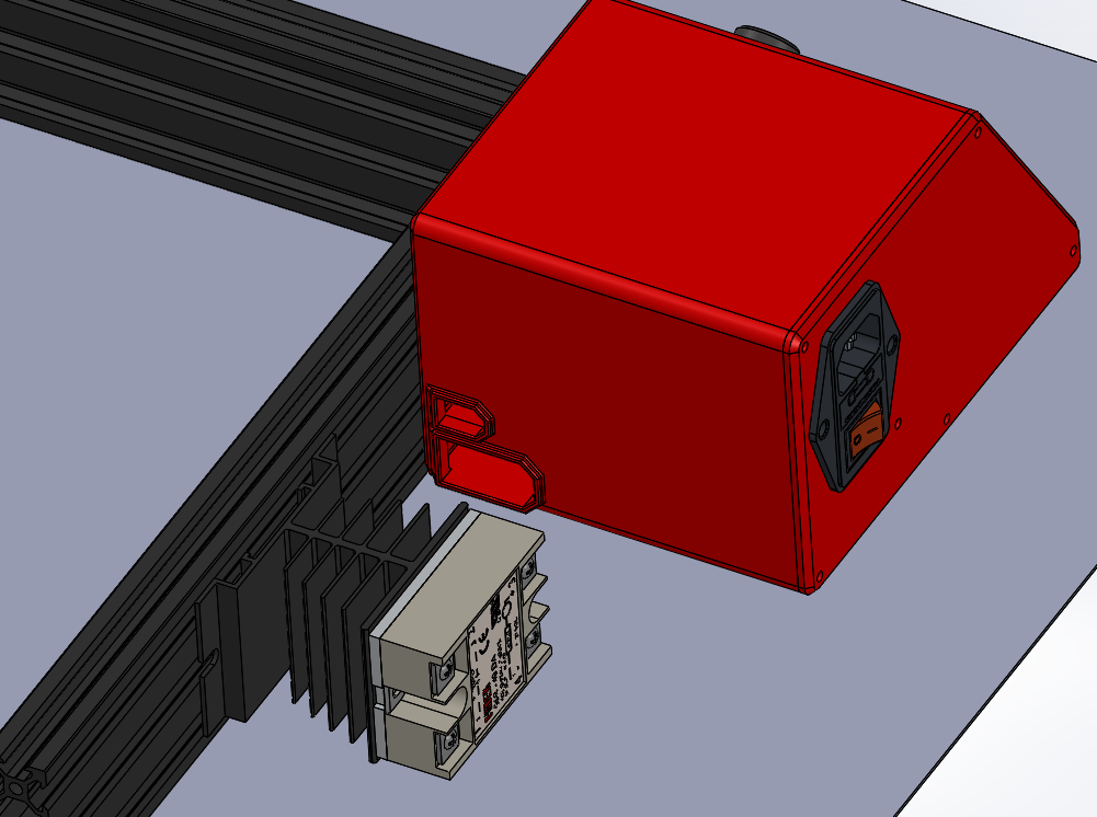
One thing is the DC comes in at the highlighted section below, so do we router the wires directly out the side of the box there onto the top of the 2060? Or do we make the box wider to allow them to route internally with the other wires?
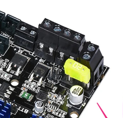
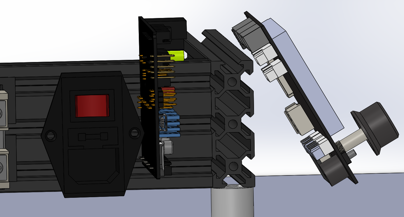
Internally, I think. Also, could align the display with the outside edge of the board instead of with the inside edge. Playing with that… Something like this?
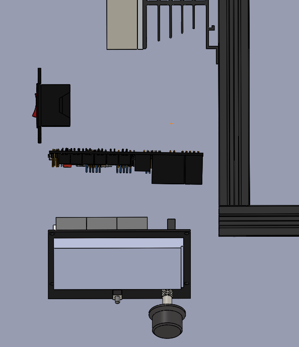
Feels like a lot of space in the top view, but honestly when packing that space full of wires and keeping in mind airflow, it’s probably not as much space as it looks like here…
Only issue with aligning the display and board on the left side is the SD card and USB is on the right side of the display.
Oh, so true! I was in too much of a hurry. (Working through SolidWorks tutorials here…)
I’ve worked through ten of the tutorials so far; the getting started tutorials except autocad import, and a bunch of the basic techniques. I’m starting to get a sense for how it works. I can see how you could get used to all this power! And setting up constraints is usually so easy… most of the time. Setting a concentric constraint and watching two parts move, with one of them moving in 4DOF simultaneously, to fit into the new constraint, is amazing.
The minor things I’m running into so far… Stray mouse clicks can easily get me to the point of no return. I find that free dragging rarely does what I want. I’m finding the smart dimension tool to be quite the pain, and I wish for hotkeys for all the separate dimensioning tools. I’m sad that parametric design is built on only excel, which I don’t have. (Many years ago, I worked on a spreadsheet, Xess, with an asynchronous engine. It was used among other things for large-scale industrial parametric design, and Excel has always seemed like a pale toy by comparison.) I have trouble imagining using it without my space mouse. It’s very pixel-hungry; I have it on a 1600x1200 monitor and my toolbars keep getting truncated and hiding important tools; the menus can’t fit on the screen top-to-bottom without scrolling. I’m guessing that normal SolidWorks users typically have at least two WQHD monitors, with at least one in a vertical arrangement? I’m pretty sure that even a workstation-class laptop isn’t the design target for this UI, especially when sharing the screen with the tutorial material.
So, two questions:
For designing cases, what is your workflow? Do you create a meaningless part (say a trivial rectangular prism) as a sldprt file, add it to an assembly with the elements you are designing around, and then edit the part into a shell in the context of the elements in the assembly? Or is there a better way I haven’t learned about?
How do you find the libraries you use for components? I’m guessing that it would be really easy for me to model the printer if I just knew where to find things like v-slot, ball screws, stepper motors, gates belt, and so forth.
I have a preliminary design done on your last placement layout that I’ll get loaded for you to take a look at. It’d probably be easiest to work with that as a baseline for how I design. I tend to create skeleton geometry either based off of projected geometry from the models, or a base sketch that I then constrain the models to so that way if I make changes to the base sketch everything else moves in accordance. I never use the Excel based constraints but you can set up global variables that you change and then everything changes with it which is where I find it most powerful.
Give me some time to get the model cleaned up and uploaded so you can take a look at it and we can walk through what changes you’d like to see.
1 Like
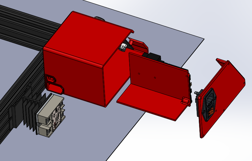
Here is my latest version. Full pack and Go so it opens independantly of the last models and all model links are integrated internall to the zip. Just Unzip and Open the assembly (subassembly parts are contained in the folders).
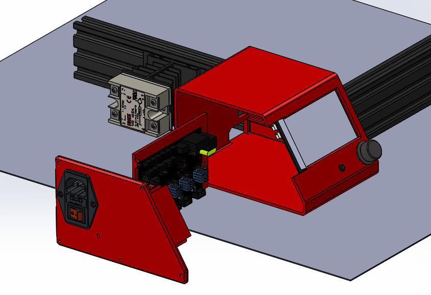
The board mounts to a removable tray which serves double duty. It isolates the DC from the AC side of the enclosure. And it makes mounting the board and the LCD much easier since getting to the far back screws on both the LCD and the Board would be tricky. The entire assembly prints in three parts and with zero supports.
Also I made use of configurations. Take a look at how they work within the models. It is likely my favorite part of designing in solidworks having multiple versions of the same thing in one structure. Dimensions, parts, mates, etc can all be actively driven by a configuration. So for example one bolt file can have 100 different configurations for different lengths, thread lengths, head styles, etc. Really powerful. Also exploded view can be configurations too which is one of the things I did to show you an example.
2 Likes
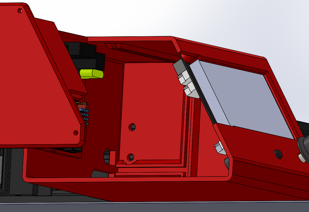
Oops, I just realized I didn’t add the rest of the bosses for mounting the side panel, only the one where it ties into the slide out control panel plate. Those will have to be added and chamfered on the backside for printability due to overhang. So you’d want to hold off before sending that thing to print
Plus it still needs ventilation holes up top and a fan mount and air inlet on the underside. Then again those would probably be good things for you to learn modifying the model.
1 Like
Yes, I was already thinking that was perfect for me learning more; I already did the tutorial for adding patterned features so I should be able to do ventilation, as well as the min-usb and microsd cutouts for the mainboard. And following your example and filling out bosses sounds like a great way to learn more! I have my evening work (after packaging up a half a gross or so of face shield frames) cut out for me!
So many thanks!

(I forgot how long it takes to punch holes in transparencies for frames when I’m sending a large batch…)
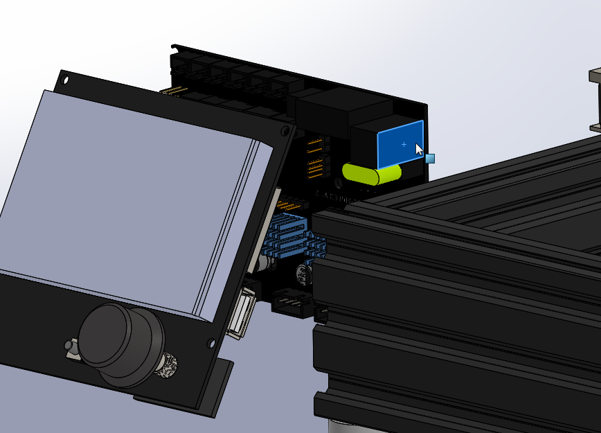
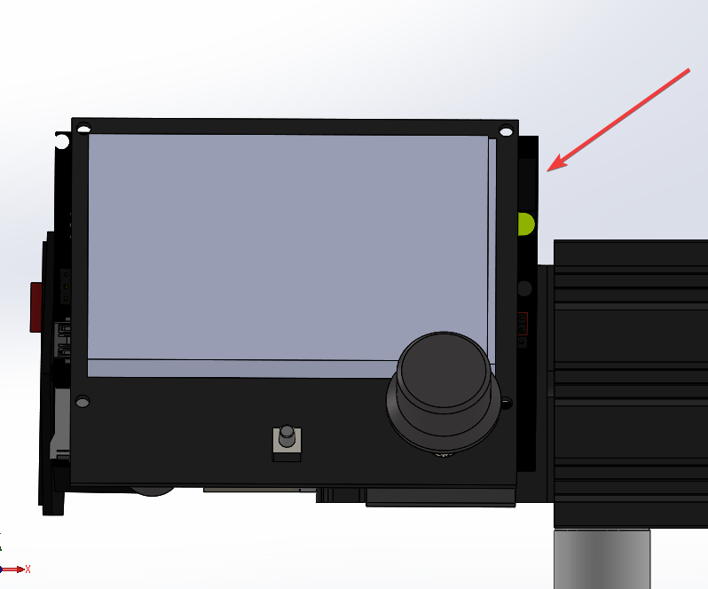
It looks like it might be hard to get a screwdriver in to fasten the display board into the front. Do you have tricks for that? It looks like that’s something you’ve already used in other designs.
My checklist so far:
- Bosses for side panel mount
- Bosses for power switch mount (want more thread engagement than the shell thickness)
- Ventilation
- slots in top, oriented to print without support
- fan in bottom, with printed grille oriented to print without support
- USB and microSD openings in side panel