Cantilever printer design based on leftovers

Been there! They get older so fast, too! And even with older ones, my corexy build took about a 20 month hit thanks to the Google+calypse — which is how I ended up here.

It’s my youngest who is the only one in the family with actual experience running a laser cutter, and has been campaigning for one. He asks me for help with OpenSCAD and slicing, and I sometimes ask him when I’m stuck in FreeCAD.

I helped a friend resurrect a printerbot simple metal a couple months ago. It was definitely solid. Just small for my occasionally grandiose prints.

2 Likes

I laid out all the parts to cut in FreeCAD as separate bodies defined by sketches, and included all the holes in the sketches to pad. Then I arranged them to cut from a single piece of aluminum plate for minimum waste, and opened TechDraw to create a drawing.

This is how I learned that if your holes were defined by circles in the initial sketch that you pad, instead of as a separate operation, the TechDraw workbench won’t show the circle center, so you can’t dimension the centers of your holes, even though it will show the radius or diameter. [EDIT: I was wrong. It’s just that the Arc Center Marks option apparently defaults to false and for every view or view object that you want to use center/arc center marks, you need to go to the View tab and change Arc Center Marks to true. Maybe this was done to avoid cluttering the diagrams, but for most of my holes I want to know where to drill them.]

I was annoyed, so I tried exporting the STEP file to try out dimensioning in Fusion360 and SolidWorks.

  • The dimensioning in Fusion360, oddly for a product owned by Autocad, was basically unusable. Couldn’t choose where to place the dimensions, and it happily scribbled dimensions over each other. Made me really appreciate FreeCAD TechDraw as generally good and usable (other than the pickle I got myself in by not knowing this quirk up front). Autodesk’s own forum has complaints about how terrible it is.
  • SolidWorks needs you to add dimensions in the model which it automatically shows in appropriate views, which probably works great if you design in SolidWorks but not so much when you import a STEP file. Also, SolidWorks pretends that US-sized paper doesn’t exist. I get it, our sizes are weird, but I found no templates for them at all in the product.

I had already wasted too much time experimenting, so back to FreeCAD. I printed out the dimensioned drawing without center marks and dimensions, took a pencil, and copied dimensions from my sketches onto the printout. So hopefully today I find time to start roughing out the parts.

3 Likes

I fabricated the parts that I designed to be cut from 1/4" sheet. It turned out I had a piece that was nearly the perfect size; relative to the “frog” that sits under the bed, only about 10mm oversize on X and about 15mm oversize on Y. From that I was able to cut all the pieces, with plenty left over in case I discover a mistake, or to use on the next project. (It’s a little silly to call it a “frog” when It has only three legs because I’m using a kinematic mount, but oh well.)

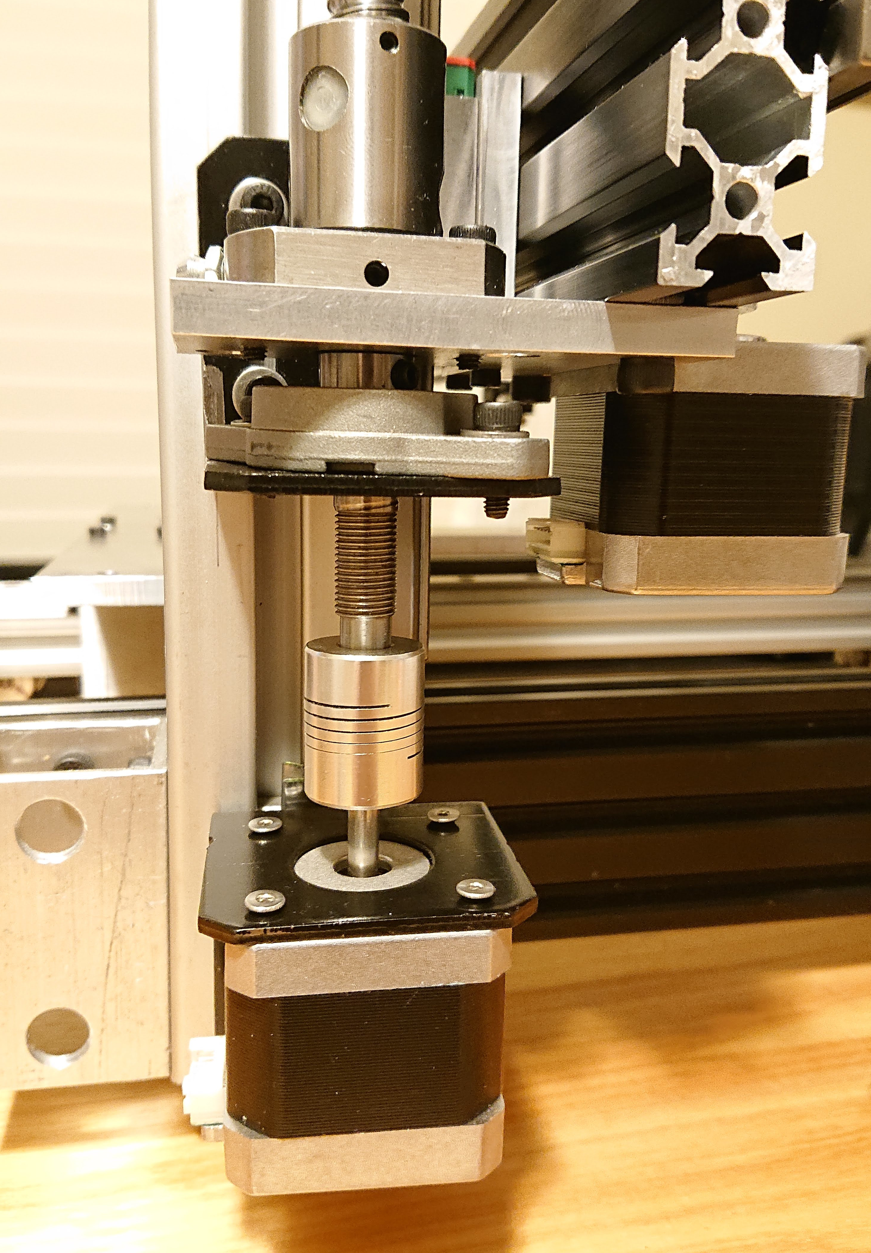
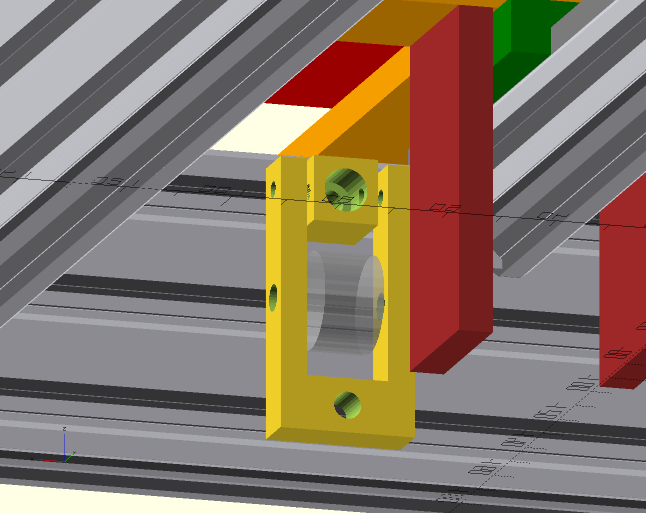
I realized — while I was making the parts — that I had modeled the plate that sits under the X gantry that the Z screw goes through, but I hadn’t measured and modeled holes for the screws that hold the Z nut to it. But with the part in the vise, I forgot that it engages with the nut, and instead made holes to fit the fixed bearing. :man_facepalming:

Since that was one of the most involved parts to mill, I’m glad there’s still enough room to put the correct mounting holes in place. It’s an L shape with an inside fillet and several holes, including one of a size that I don’t have a bit or end mill for, and had to use a boring head instead. So glad to assume for now that I don’t need to start over. But I think I’ll get to the point of assembling the printer before drilling the final holes.

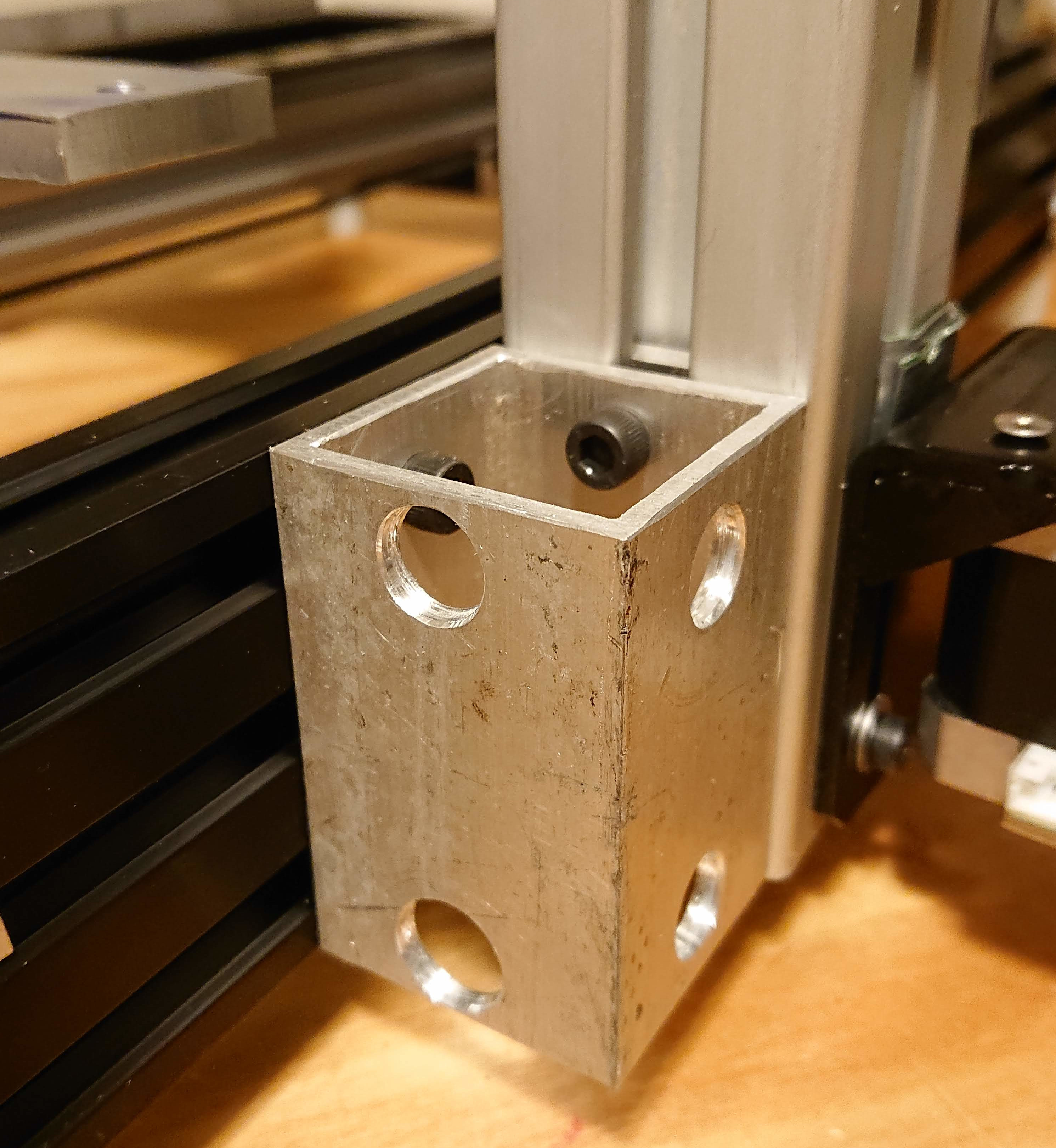
I also thoughtlessly drilled the holes intended to be tapped M5 with a 4.5mm drill bit. When I tapped them, I finally remembered that M5 should be drilled with the 4.2mm drill bit I don’t have as a metric bit, and I should have used a #19 instead. One of them I can change my original plan and just drill it out to 5mm. But three of them are for my bed’s kinematic mount. I’m wondering whether wrapping the M5 screws in many layers of teflon tape will both solve the oversize hole problem and function as insulation, killing two birds with one stone. Otherwise, I’ll have to figure something else out.

I keep forgetting how much I hate tapping M3. Especially blind tapping. Going slow, backing out and cleaning the tap every few mm, then finishing with a bottoming tap. At least I didn’t break a tap. But some of the holes were over 10mm deep. That was slow going.

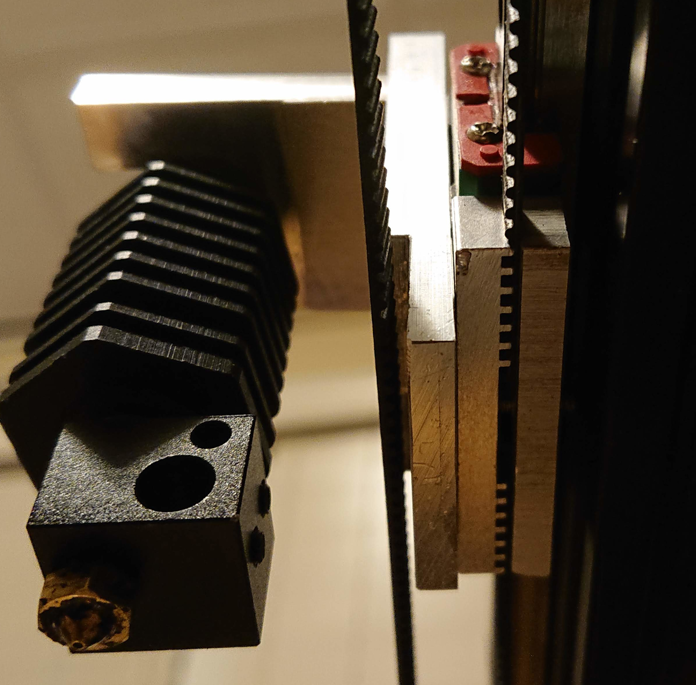
I haven’t yet designed or made the Y belt bearing mount. I’m trying to make something that installs easily on V-slot. But I’m not 100% sure which orientation I want to mount the Y motor in, which would change the design of the mount. Also, I haven’t yet drilled holes to mount the Y belt clamp into one of the “saddle” pieces that extends below the bottom of the Y block, because I first have to decide about the Y belt. Once I decide it should be easy enough. But I’ll probably wait until I’ve assembled the frame to make a decision.

I haven’t cut the kinematic mount features in the bed. I also plan to use the heated bed that came with the donor printer as the heater for the cast aluminum plate bed that I’ll mount, but haven’t yet figured out how I’m going to bond them together. Some invention still required there.

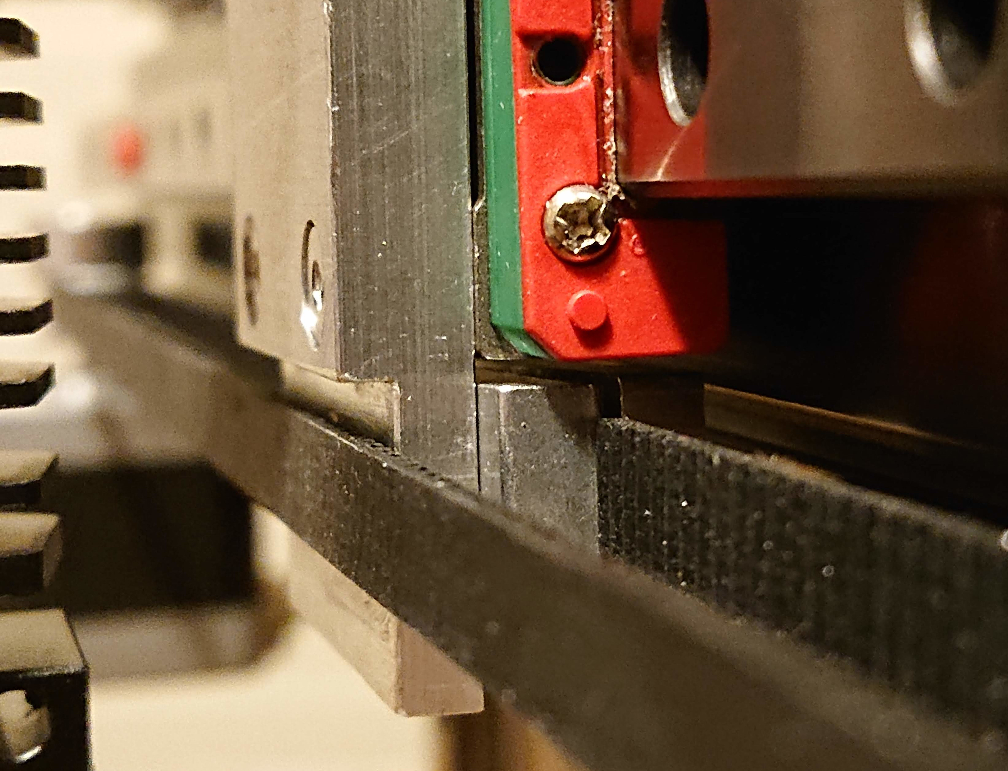
I made the design so that I could build it with what I had at home, but I also ordered a few parts to make it easier or better. I have plenty of microswitches, but I bought some optical endstops instead. (I was buying them anyway to improve the other printer, and they came in a set of six, so might as well put them on both printers.) I have scrap to make mounts for the Y motor, and the Z motor and nut, but I bought some NEMA17 angle brackets which might make it easier.

I plan to try printed cable clamps to start with for X and Y. I ordered an inexpensive set of aluminum clamps, though, in case the printed clamps don’t work well enough.

3 Likes

I just realized that I should have made the Z lift plate also hold the X motor. Then I wouldn’t need to cut the X beam. I think I can make it work without cutting a new Z lift plate by attaching the motor with only two screws. If that doesn’t work, I can fix my nut/bearing confusion while cutting a new Z lift plate. I’ll have to mill away some of the plate to make the motor fit, but I think it will be OK.

It’s hard to see in this animation, but I added a belt clamp behind the hot end mounting plate.

3 Likes

I’ve assembled most of the Z stage and it looks promising. I was able to attach the motor to the existing Z plate and it looks like it’s going to work well. I’m using flat-head M3 screws where I need flush screws, and it turns out a 6mm drill bit is the perfect countersink for them. Tonight was taken up with preping a pile of 3DVerkstan frames for first responders lacking PPE, but back to this build shortly!

3 Likes

Status update:

I bought some NEMA motor mounts with the idea that it would save me some time. I may have spent more time altering them to fit than I would have fabbing from scratch from square tube, and I forgot to adapt the model for the slightly thinner metal (about 1mm) and it left me with Z screw alignment issues that took a while, and some shimming, to resolve. I’ll know whether I got it perfect when I install the Z motor.

I needed a stop to make sure I don’t run the Z nut off the top of the Z screw, so I made a knurled knob that will let me adjust Z when the printer is off that also functions as a stop. :slight_smile:

I used a crosscut saw with a good carbide blade to cut the v-slot. It made nice clean square cuts, and the frame assembled square with no “convincing” or shimming; I can’t see light shining through when I hold my machinists square to the corners. My youngest drilled all the base frame holes. I showed him how to set up a jig on the mill, and the square fit shows that he did a good, careful job.

I should have included spacers in the design between the Y carriage and the “frog” to leave more room for bed adjustment screws. I’m using some 6mm openbuilds spacers right now to give myself a little more space. I’ll see if that’s enough; if it isn’t I’ll have to source longer screws as that has me using the longest flathead M3 screws I own, countersunk as deep as I dare.

I decided not to cut the tower piece down to 500mm. It’s tall, and I can hang the filament spools on it, above the print area. I gave myself about 15mm extra room on X and Y vs. what I modeled in case I forgot something, and it made it possible for me to put corner brackets inside the frame. I didn’t cut any of the 450mm MGN12 rail, so it sticks about 20mm behind the printer, so in retrospect I should just have designed it to be 450mm long. I also made the X beam longer than needed, because I used the offcut from cutting the shorter frame pieces out of a 1m section and didn’t cut it further. That way if I need to slide it around (say, to accommodate a second tower as discussed above) I don’t have to trash it and start over.

I didn’t model how to attach the tower to the side before I started. I used a piece of square bracket, screwed to t-nuts in the frame v-slot (the thick slide-in kind, not drop-in) and to a custom double t-nut in the 4040 t-slot that I’m using for the tower. Both use M5. I put a few extra T-nuts in the frame before putting loctite on the screws to hold it together. I’ll see whether that’s sturdy enough or not.

Not yet done, at least:

  • Electronics: nothing done yet; no wires, no routing, not even much planning, no electronics enclosure design
  • Mounting any motors
  • Fabrication:
    • Y idler pulley tensioner mount
    • Y belt clamp for saddle
    • X idler pulley rod
    • Extruder mount
    • Heated bed (planning to use an old heated bed as a heat source for a new cast aluminum bed plate)
3 Likes

My plan is to use the bed from my old hictop gantry printer as the heating element, at least at first. I want to hold it to the cast aluminum plate. That bed is marked for 12V and 24V but 24V is probably about not overwhelming the power supply, and of course the alternative is to use a a more powerful 24V supply and get 4x the power output.

I’ve been using that old gantry printer’s heat bed for mask sterilization. I set the bed to 75⁰ and put the mask on the bed, under insulation, for about an hour (Stanford protocol is 70⁰C for 30 minutes, and it takes a while to heat up, and the insulation isn’t perfect). But today, I used polyisocyanurate board to make a filament drying oven over the old bed and control board from my tronxy, so my heater is available.

It was bittersweet to tear down my first ever 3d printer for spare parts, but it’s done now, and no going back. I was a little low on M3 hardware, but not any more!

I finally realized that the heating element bed does not fit my plans for a kinematic mount as is; it is too big and I can’t mill through it and have it still work. So instead, I’ll mill kinematic mount features in small pieces of aluminum and glue then to the heating element with high temperature RTV. Then if I get a different heating element, I can switch to milling kinematic mount features in the plate itself.

Today I tried to buy RTV high temperature silicone because the tube I already had was dead, but the particular home depot I went to happened to be out. So I ordered from Amazon instead, but it will take a week to get here. Maybe I’ll get impatient and go shopping again.

I didn’t make much obvious progress on the printer itself today. I made the X idler bearing pin. That enabled me to discover that the X belt mount arrangement I had come up with will rub the belt, so I have to make a new part that’s a little more compact. Not hard to make, just a little frustrating to have to start over on it. My measurements were with a different belt mount (printed in ABS), that turned out not to be quite strong enough. I have yet another design, I just need to spend a little more time milling out a new part.

3 Likes

Turns out that moving the motor back a bit for the Z lift plate fix also threw off my belt alignment calculations, which were imperfect to start with, so I had to take 2.5mm off the bottom front of the X carriage mounting block to avoid rubbing the belt. It’s not perfectly aligned end-to-end so it won’t run true, but since the carriage won’t get closer than about 40mm to the motor pulley and it’s off by about 1mm, the cosine error won’t be significant. I think.

I attached the Z stage motor, which finally set my minimum Z height. I have about 35mm between the top of the “frog” and the end of the nozzle. If I end up wanting a little more, I can slide the Z stage higher.

2 Likes

Finally came up with a design for a Y idler tensioner that I’m happy with; a relatively simple hinge.

  • The block at the top is screwed into a T-nut in the top slot with an M5 screw
  • An M3 screw forms the hinge pin through the top of the arms and the block
  • An M5 screw through the middle of the arms holds the idler pulley
  • An M5 screw in the bottom of the fork frame screws into a T-nut in the bottom slot and tensions the idler pulley.

It’s sized so that I can upgrade from the 6mm belt I have now to proper 9mm Gates belt now that I know where I can get that conveniently (Belt, for $1.50/100mm idler for $7 and pulley for $6) — 6mm belt for the X is fine, that doesn’t have much mass, but a thicker belt for the bed might turn out to be a good idea so I’d like to leave room for it.

I think I’ll fab that tensioner, then cut the belt, and drill the saddle (red, next to it in the model) wherever makes the belt run flat without trying to model it more thoroughly.

1 Like

Of course, this other project used up the 24V power supply that I had intended to use for this printer, and my remaining supplies are 12, 36, or 48V, so I had to order another 24V power supply. I’ll just consider power supplies fungible and think of the one I ordered today as having been bought for my drying oven, not as breaking my “leftovers” design constraint further. :smiling_face: Sadly, the MeanWell 24V 350W supplies don’t seem to have a thermostatically-controlled fan.

1 Like

@Eclsnowman since you are using an SKR mini E3 v1.2 with at least one printer, did you get the TFT35-E3 as well? If so, did you design an enclosure for the pair? Right now, I have the pair sitting on the table next to my printer and it’s kinda ghetto, and while I could design a case I figured if I can cadge a case design off a friend why not? :wink:

1 Like

I have an enclosure design for the board that could be modified pretty easily. I have one of the minis on my ender 3, and I thought I messed up the boot loader so I bought a replacement board but then figured out the issue was with flashing it a firmware above 256k without using the 512k hack. So I ended up with a second one and replaced the controller board on my Talos3D Spartan. So that’s the one I designed the electronics enclosure for, cuz the under 3 already has the standard enclosure.

I don’t have that particular TFT, I just did the wiring hack to hook the smaller tft control to it. But to be honest I like the interface better of the Marlin non-touch screen. So I almost always run the screen in Marlin emulation mode. Instead of the standard touch interface.

1 Like

Give me some time here tonight and I’ll get the files together for you, what format would you prefer them in for modifying?

As usual, you do beautiful designs. :slight_smile:

I also use marlin mode instead of touch mode for pretty much everything except typing gcode into the integrated terminal, thought I might be the only one…

That design won’t work for my corexy, but it sure will for the new cantilever printer which is nearing functionality :crossed_fingers: 
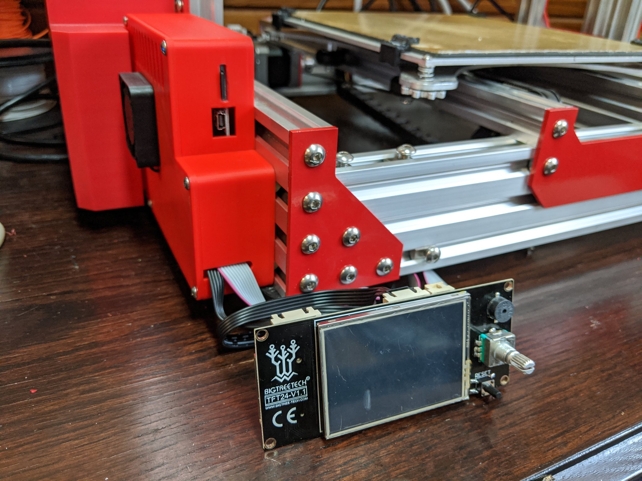
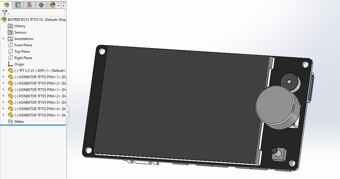
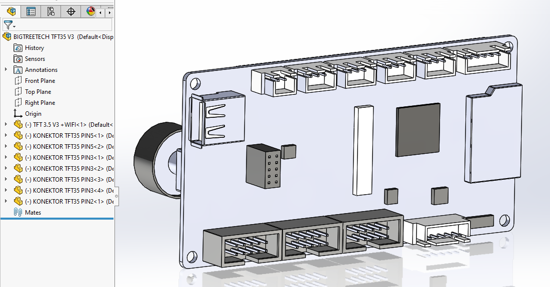
so that would be awesome! I would have to modify for the TFT35.

As of recently, I ended up installing Fusion360 on the windows machine, and I’m an EAA member, so SolidWorks is also free for, me so I have that installed too. So probably whichever is native is most likely to be useful. I keep working in openscad and FreeCAD because I hate lugging out the windows machine when I’m overall so comfortable in Linux. :slight_smile: So I’m pretty much the confused user in Fusion360 and SolidWorks still. Therefore, I might have some learning to do to modify the front for the TFT35.

1 Like

Here is a google drive download for the files. I have them in Soldiworks 2018, as well as Step, and X_T. I also had been looking at the TFT35 V3 before, so I had a model of that and chucked it in there for good measure. Should make designing a case pretty easy. If you want any help on that front let me know because I am pretty quick at knocking things like that out. Only thing to watch for is I didn’t make that TFT35 model so an enclosure for it might take a test run to confirm all that modelers positions were correct.

Here is the link for the downloads: https://drive.google.com/drive/folders/1vlIBAw07zbvf0dH1GCBH8gQeaQIjFoda?usp=sharing

And here are some pictures of the model I had found for the TFT35, it looks like good work by who did it:

1 Like

Thank you!

I am discovering in practice what I knew in theory: That some OpenSCAD and FreeCAD experience doesn’t make SolidWorks obvious to me. I’m guessing I’d need to go a long way down this rabbit hole to learn what I’m doing. I’ve literally only opened a few files and poked around before, never even tried to edit anything.

I want to get there, but it’s slow going. I figured out how to the the TFT35 inserted into the front cover in place of the the smaller display. But lots of “The selected component is fixed, it cannot be moved” when I try to move features on the enclosure to make them match the TFT35 display. I’m guessing there’s a way to select features and move one to match another quickly.

I feel like “I’m not a doctor, I just play one on TV”, or maybe waking up unexpectedly in Portugal and discovering that a smattering of French and less of Spanish isn’t the same as being able to speak Portuguese. I’m clearly wielding a power tool while unsure which end is the business end! :rofl:

1 Like

Several of the features of the housing are designed using “in context” constraints to the assembly. So the features are actually tied to each other and their respective models within the assembly. It’s a top-down vs bottom-up modeling question. If you give me an quick sketch of where you want the display mounted on your printer I can wipe up a quick concept. I like these sort of projects.

That would be very kind!

What you have designed, without the power supply holder, and accommodating the larger TFT35 display, would be perfect for the cantilever printer! (I’ll tuck the power supply away somewhere else; it would get in the way of the X motor on the Z tower for my design.)

I hope to be less helpless when I have a chance to learn more. :slight_smile:

Do you have your current printer design in a form of Cad I could pull into SolidWorks? Like step or something similar? If so I could model the mounts for the LCD and the controller around that to make sure I’m not obstructing anything. Either that or even a dimensioned 2D front view and side view so I knew what heights to stay below (for example so I don’t have the LCD sticking above the bottom of the bed where it would come in contact with it.)

Oh, the model is only in OpenSCAD, so I’m not aware of a good way to do any import that would pull into SolidWorks. It can produce AMF, but I don’t see importing AMF in the solidworks help. I tried using FreeCAD to convert the OpenSCAD to STEP but no luck. If I’d designed it in SolidWorks I could probably just tell it to make drawings for me, but then I would also know how to modify it myself. :rofl:

I think I should just make a design that attaches to the side and doesn’t wrap around the front. It would give me more freedom to modify the printer later. :slight_smile:

1 Like