Bump. Would really like to order this week as I am sure things will take 2 weeks or so to get to me…
Mike, do you have a digital multimeter(DMM)? Hard to believe both of those inductive sensors have failed.
Can you provide the part number for the inductive sensor and provide pictures of the wiring, specifically where it’s connected to the C3D board so that I can see the color codes. Also a picture of the sensor if it shows pin numbers or wiring information on them.
In general, you should be able to validate the proper voltage on the proper wires to power the sensor and then with the DMM across ground and the trigger wire should be able to move a piece of iron/steel towards and away from the sensor and see the voltage change.
1 Like
Thanks Doug, I do have a DMM, not sure how to use it to test the sensors though. If you are able to walk me through it I can give it a shot.
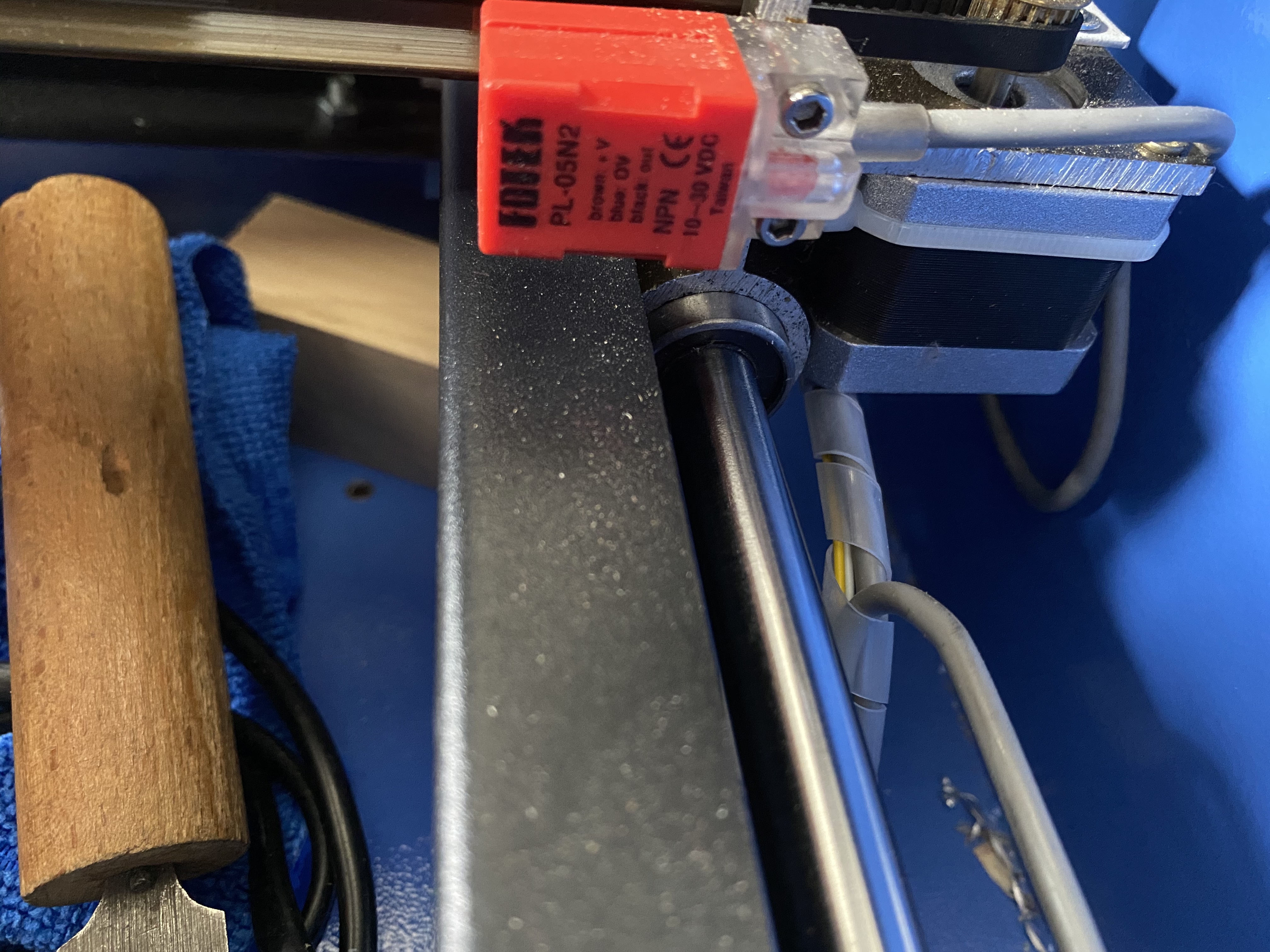
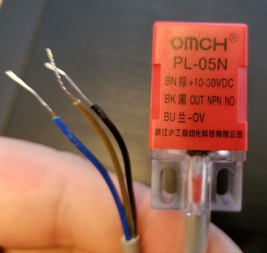
Looks like the part number for the sensors is as follows: PL-05N2
The cohesion mini board has its own 24v power source as well if that means anything.
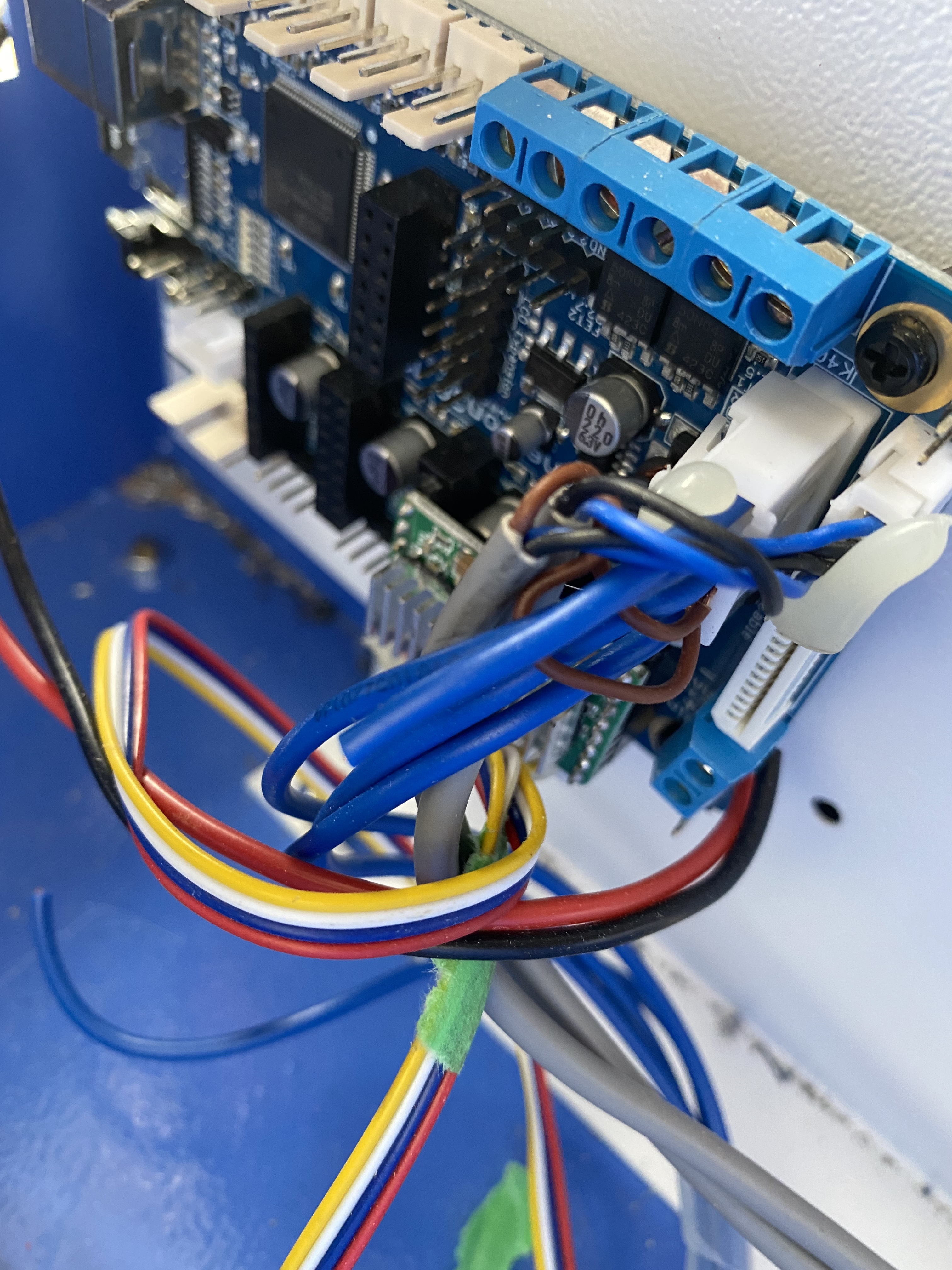
Here are the photos of the wiring:
Uploading: 2E1AB0B8-B6EC-422A-9726-7CE19741B5F9.jpeg…
Uploading: 6E7AE27A-74D6-4D29-83F3-97FC251CCF34.jpeg…
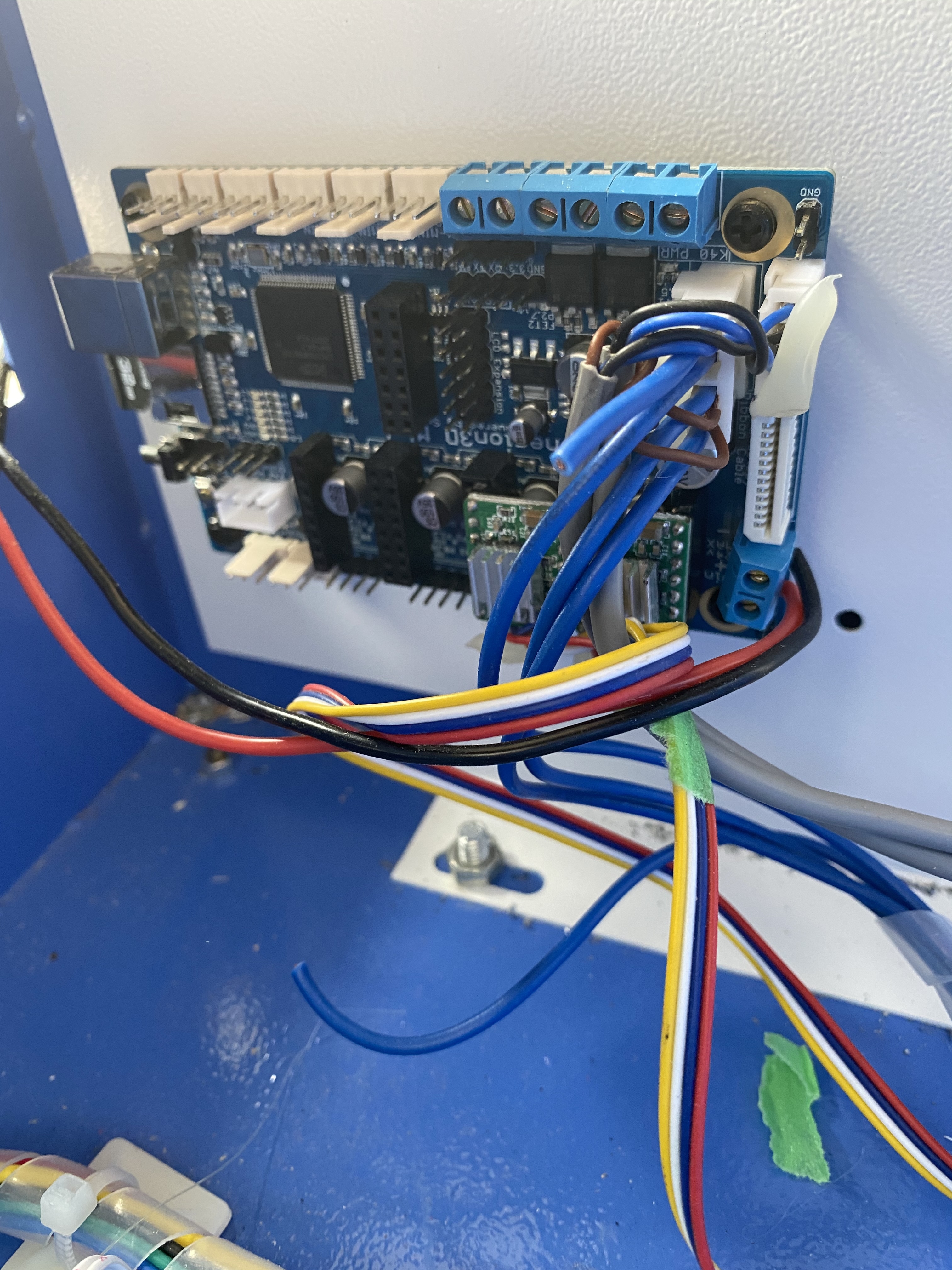
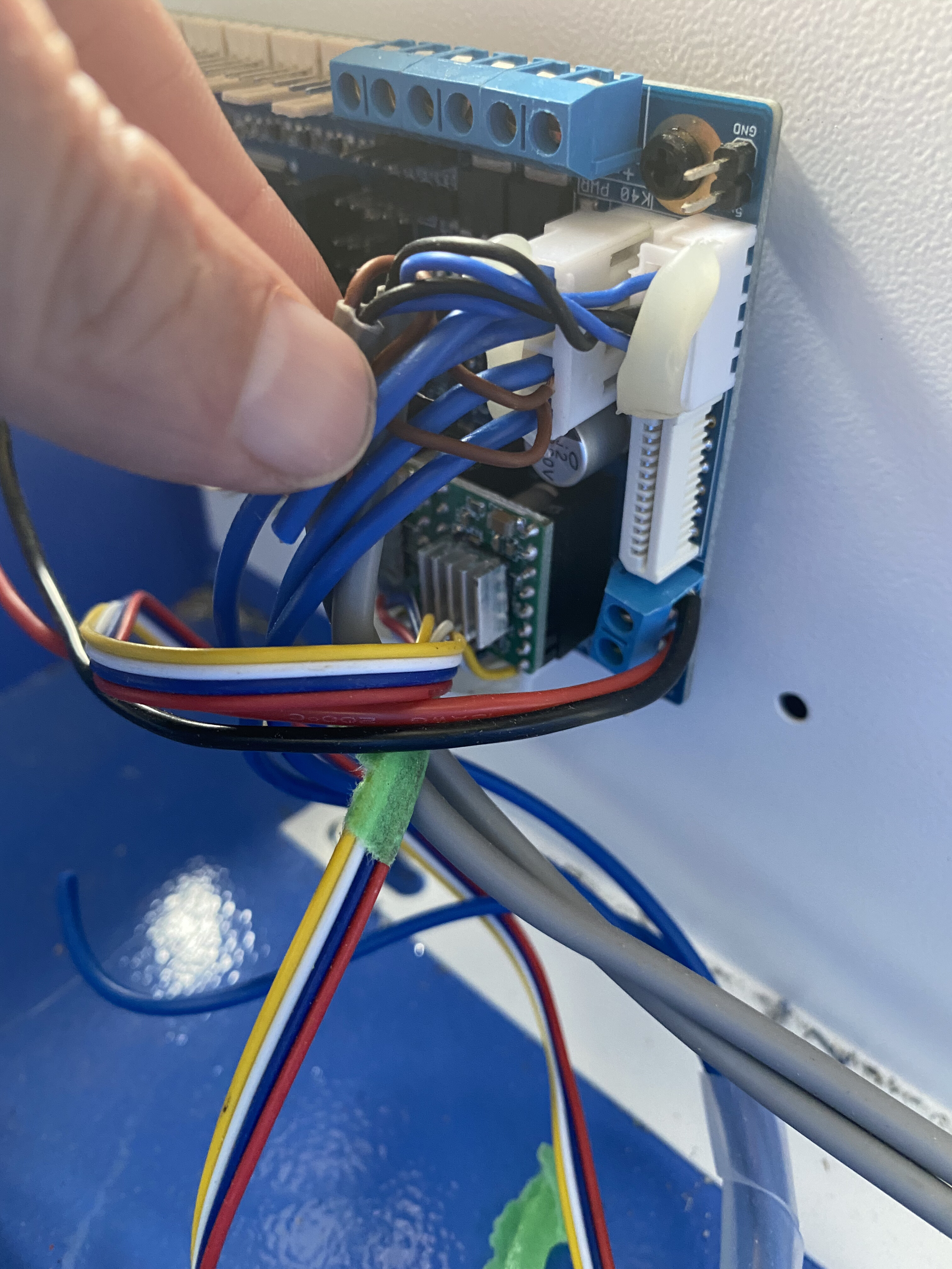
To start with I would advise getting some connectors and wiring the endstops to the 3 pin white endstop connectors. Stuffing the wires into that high density connector is asking for shorts and intermittents.
I also think that microswitches would be a simpler end stop sensor.
For reference:
The PL-05N2 requires 10-30V which I do not think is available on that white high density connector?? You will need to get the correct voltage from somewhere on the board.
3 Likes
I can not make out the manufacturer name but I can make out the 3 wires:
Brown = +V
Blue = 0V
Black = output
10-30VDC
-
So you should be able to put your DMM to DC Voltage, the neg/gnd lead(black) to the blue connection at the C3D and the red test lead of the DMM(positive) to the brown wire connection at the C3D and hopefully read a voltage. Report back.
-
move the red test lead to the black wire connection at the C3D and you should see 0V voltage there. If you move a piece of steel/iron metal within 5mm of the sensor you should see a voltage appear. Report back.
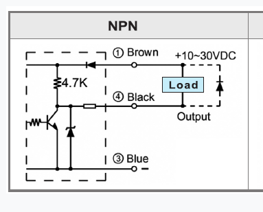
FYI, that sensor is a Normally Closed(NC) device which means it will be biasing the NPN transistor inside the device pulling what’s connected to the black wire to ground. That way the endstop circuit is triggered on a positve endstop signal so if a wire breaks the endstop gets triggered AND when the sensor is triggered with metal nearby the endstop circuit is triggered.
I had not seen/noticed the C3D board had that high density socket which you had jammed incompatible end stop pins into. As you can read on the sensor it requires 10VDC through 36VDC to work so I hope you verified you have 12V or 24V on that connector where you put the brown and black wires/pins.
If you get proper connectors to use the discrete endstop connectors you can wire the ground(black) and signal(Blue) wires to the endstop connectors and tie both Brown wires together and connect to 12V or 24V to power those sensors.
(note there is a product manual .pdf at this link but it is to large)
I do not know what the the endstops connect on the laserboard, I suspect through a filter and then to the uprocessor. I would not trust connecting the output of this sensor potentially pulled up to 10-30 volts to that input.
2 Likes
Thanks, the image of his endstop was poor and I thought black was labeled as ground but it is “output” and the Blue says 0V which would be ground…
If we knew what that zener diode is across the transistor it might be ok to use and supposedly others have used these with C3D boards but having to power them separately from the 5V provided on the endstop connectors.
He should be able to measure what’s on the output(black) with just 12V or 24V on brown and ground on Blue.
Ok I’ll see if I can get the meter on it tomorrow and get some readings.
Thanks for the photos as well all.
It wasn’t me that wired it, so not sure what the original user did or if he verified voltage.
I don’t even know which are high voltage sockets or why they would be.
I’ll test and get back to you both, it is sounding like mechanical end stops may be the way to go with minimal tinkering. At least that is what my brain is starting to understand lol
If it were me I would not chance having higher than 3-5V show up on the inputs to the laserboard. Microswitches are cheap controllers are not.
1 Like
mechanical switches will work but you then have to solder wires and then wire them to the C3D and will need instructions on that. Plus you’ll have to properly mount them so they trigger/hit something and the mount is adjustable, unless you’re ok with losing some work area.
Those were probably wired to an M2Nano board originally.
True that but he has to make connectors to connect to the laser board properly anyway :).
The wiring is explained over on the C3d forum.
I would just buy the endstops from C3D … they are prewired.
Yes a bracket will need to be made.
Here is a 3d printed one. K40 Mechanical Endstop / Limit Switch mount by Venomouse - Thingiverse
And as I am dissing on these switches I find this:
3 Likes
I’m with you Don and up until you showed that Ray ‘has a document for that’ I was going to say to just go for Ray’s prewired mechanical end stops.
But it appears there’s no problem using the 10-36V inductive endstops with the C3D but they just need 24V which they can get off the wire terminal since it seems to be wired to the same 24V input of the C3D power supply.
@LETZRIDE Mike are you ok with following that document for connecting the inductive endstops?
2 Likes
My head is spinning but I am trying! Dumb question, when I test the switches tomorrow do I have to put power to the c3d board? Or have it unplugged entirely?
As far as following that guide, I am having a bit of a hard time understanding this:
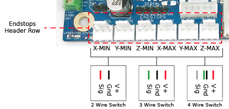
24V Wiring
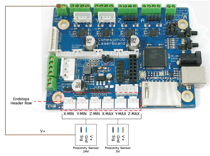
The versions we have seen of these types of proximity sensors have been connected to the 24V on the LPSU. Disconnect from the power supply / stock board and connect +V (Brown) to Separate Power IN + in the upper left corner of the board, then 0V (Blue) to Gnd, and Out / Output / Load (Black) to Sig for each respective axis. See Proximity Sensor 24V in the left example of the Endstops Header Row image above. Note that there is no connection for the V+ pin on the right.
Where is power in? How do I know what the upper left corner is? The board in the photo on that link is not a mini, so it is a bit different and therefore confuses me.
For the ground, am I attaching to this red circled pin?

I then don’t understand what it is saying for the black wire?
Also, would the x and y wires be combined together and put to the same pins? I.e sensor x and y blues tied together and put to one pin, browns tied together and go to another, etc?
Sorry for the dumb questions…
that section shows a picture and if you look at where the wire drawn in and labeled V+ goes you can see VIN on the board and the connection indicated to the + side of the connector instead of - side.
Maybe watch this video a few times to get a handle on what a circuit is and to understand what’s being asked? It should explain what you have been doing with the volt meter and give you and understanding of why you would not be trying to measure a voltage with no power connected to a circuit. Electronics 101: What is electricity? - YouTube
So would both sensor brown wires go to vin + then? Do I understand that part correctly?
Each endstop sensor is a circuit and needs to be powered to be functional… So yes. But please watch that video since it will give you an understanding of things which go way beyond this current issue(s).
So I got 0v no matter what when I used the DMM. I even used paper clips to make sure I was touch metal with my probes
so there you have it and as suspected, how-ever the endstop connector is jammed into that socket, it is not working.
Did you ever find a pin numbering and description of all the pins in that connector?
Regardless, that was not the way to connect these end stops so you should wire it as the documentation states to wire it and go from there. I’ll spell it out:
connect BOTH sensors Brown(20-30VDC) wires to the 24V + wire terminal which it looks like you are supplying 24V to the C3D board from an external power supply. If you want, you can also connect both of the Blue(0V) to the 24V - wire terminal and then you just connect each of the Black wires to the proper X-Min Sig and Y-Max Sig pins on the C3D. I think that’s what the document says for the configuration file.
If you are wondering if it will work, use jumper wires and connect it temporarily.