Sorry for the delayed response, I am in the middle of initiating a move and so I am juggling quite a bit, bare with me.
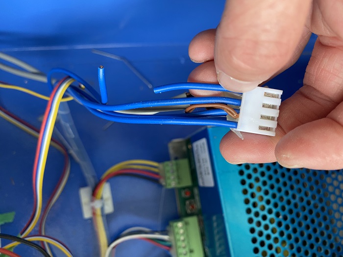
I have no clue what that pin connector with all the blue wires is for. I am going to post a picture of that below this response with a picture to see if I can figure that out next.
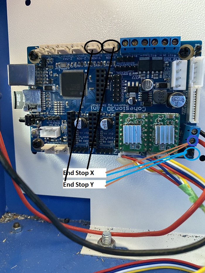
So Doug and Don if I understand correctly, I drew up this diagram using my board below. Both brown wires from each end stop are going to go to the red port on that blue plastic holder which I am thinking is “hot” power. (Atleast red is hot in the automotive world, I think I remember in houses black might be hot?). It’s hard to get my head into there, but I believe the red terminal is the one that says V+
Then the blue wires I will tie together and put to either one of the GND terminals, OR I can put it to that same blue plastic holder on the bottom right, but tie it in with the black wire instead of the thick red wire?
THEN, I take the black wire from X and take it up to signal X and Y to signal Y?
Do I understand that correctly?
What type of connector do I have to buy to get it to go onto that male fitting? Is this something standard I can go into the local circuit board electronics shop and ask for a ________- and they’ll give it to me? We have a small mom and pop store not far from here that sells all sorts of circuitry stuff, just no clue what size or item this would be called to ask for it.
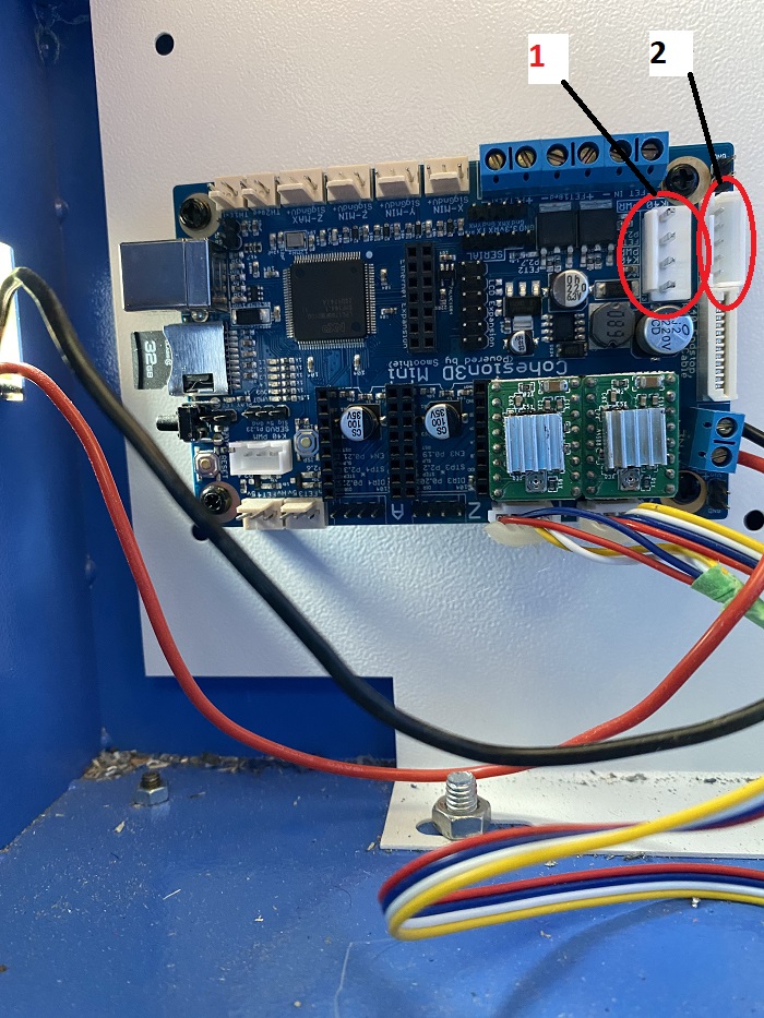
Next, I also labelled this diagram circling what I call #1 and #2 - what are the connections that go here? One of the connections to number 1 has one of its 3 blue wires cut, and I don’t know if it is supposed to be like this, or what the heck it is for?
you have that correct, ie the VIN screw connector in the bottom right is where you have 24V + and 24V Gnd connected. Take one endstop and connect the brown wire in the same side as the 24V +(red) wire then take the blue wire from the same endstop and connect it with the 24V gnd(black) wire. This is what supplies power to the end stops since they are NOT mechanical endstop and need to be powered with something between 10 and 36VDC. 24VDC is between that range.
Now find something to connect the black wire from the endstop to the X-Min endstop Sig pin on that connector on the other side of the board(white conectors).
Remove the stepper motor wires from the connectors and test the X endstop to see if you can get the software to report a change in signal level for the X axis. If that works, move the endstop wire connected to the X-Min signal over to the Y-Max and test to see if you now see the Y max change when you do the endstop test. If it works, you can now connect the Y axis endstop just like you connected the X axis endstop except you connect the black wire to the Y-Max signal pin.
I hope you have already ordered a set of the mechanical endstops… they are inexpensive, are pre-wired and you would just need to mount them. Worst case you cut the wires and have a connector for your existing endstops if you verify they work.
Connector #1 is the connector which originally came from the Laser Power Supply(LPS) and the 4 wires/connections are 24V / GND / 5V / L The Laser power supply originally supplied 24V to the M2Nano board for powering the stepper motors and it supplied 5V for powering the M2Nano board. The L signal is the pin which tells the last to fire or not fire and is controlled in software(LightBurn) to turn on/off very fast and at different rates so that different power levels in laser output is the result.
As you can see the 24V and 5V wires have been cut which leaves the Gnd and L signal. If you look at your LPS you will see the connector the wires lead back to and should be able to follow them to the pins labeled GND and L. Again, connector #1 is for this. Please look at this installation guide and you will see where it says to remove that connector and move it to the C3D board. New boards don’t require you to cut those wires and come with its own 24V power supply so the instructions vary slightly.
The #2 connector looks like it might be for endstops but mechanical end stops, not inductive endstops needing 10-36VDC and that’s probably why they didn’t work. The X-Min and Y-Max endstop signals might be in that connector but I don’t have a schematic so don’t know for sure.
Please verify you do have the GND and L wires in the #1 connector correctly installed.
Sorry it has been a year, I moved and had too much going on to focus on the laser. I finally have settled in enough I can go back to throwing some time at this.
Today I rewired the inductor endstops as outlined in the few posts above. I thought I had it figured out. I ran some tests and the endstops were picking up. Putting the laser in the top left corner I got:
X_min:1 Y_max:1 Z_min:1 pins- (X)P1.24:1 (X)P1.25:1 (Y)P1.26:1 (Z)P1.28:1 (Z)P1.29:1
If I moved the laser to the right 1 position I got
X_min:0 Y_max:1 Z_min:1 pins- (X)P1.24:0 (X)P1.25:1 (Y)P1.26:1 (Z)P1.28:1 (Z)P1.29:1
If I moved the laser down 1 position and right 1 position I got:
X_min:0 Y_max:0 Z_min:1 pins- (X)P1.24:0 (X)P1.25:1 (Y)P1.26:0 (Z)P1.28:1 (Z)P1.29:1
Which I believe tells me the endstops are reading correctly now.
I have been playing with it without the laser on to make sure I can get it to go everywhere I command it to do so. Seemed like everything was going great until I drew a rectangle with a circle in the middle of it in the center of the work space. I tried to do a dry run and the laser went everywhere but where I commanded it to go.
I am back to being stumped. I really thought I had it figured out.