Wow, I thought I had this build beaten this weekend. I had to replace me X-Axis stepper and I have great movement control down which seems to be a moderate challenge. My big problem now is not getting any sort of laser fire. I’ve traced my wires and checked my connections. Should I be able to test fire without any sort of fire control from the smoothie? Seems like it should be independent unless there is code being sent. I’ve been using Don’s guide all along the process, but I am at a loss at the moment. I have a replacement tube and power supply, but I would rather troubleshoot what I have in the box now before I start swapping components. I don’t really have the capability of testing High Voltage output, but I do have a standard multimeter. It looks like I have a G-G-G or a Type “C” power supply. Any help would be appreciated!
You should be able to fire the laser without any controller as long as you have the laser enable asserted.
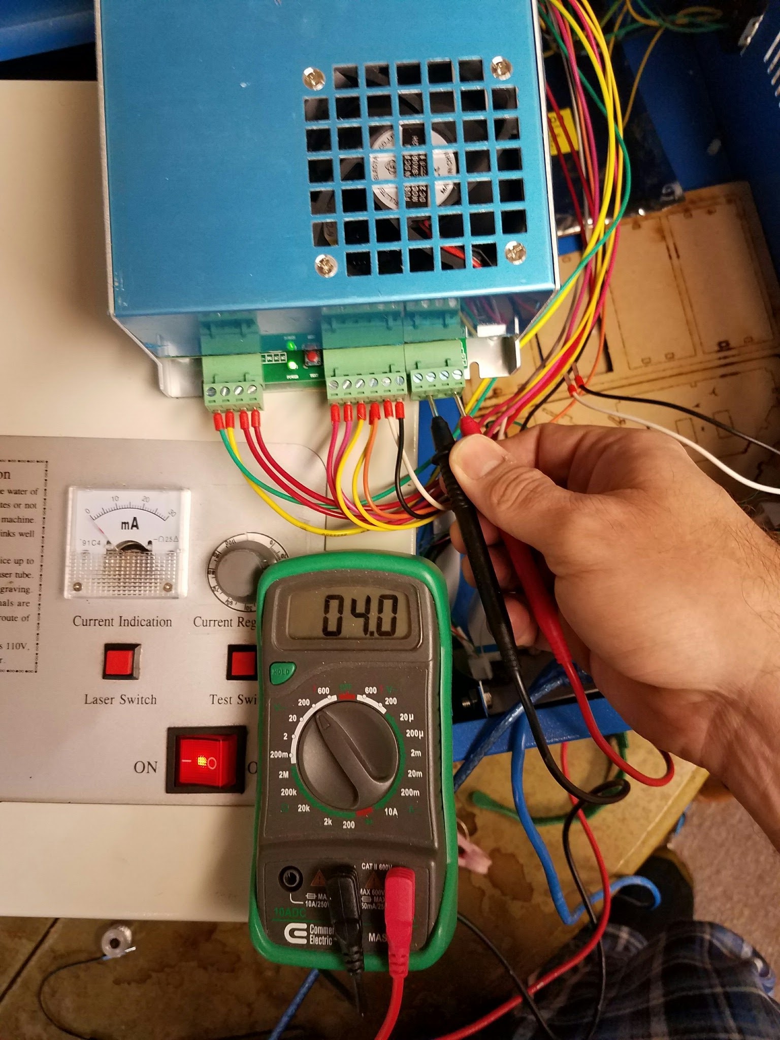
Is this a STD K40 panel and wiring?
as long as the WP circuit is shorted then the test button on the front panel should fire (or the one on the LPS itself). I don’t know if this also works for the software button in LW as that is by code not just a hardware circuit.
On your C type the enable loop should be the left two pins on the 6 terminal connector.
Thanks for the guidance, and thank you Don for for all your hard work on this project. Here is a picture of my setup. I will check the wiring back to the PS to make sure that I should be able to fire. Honestly, I’m almost ready to hang it up. The stock setup work so well for me for like 6 months, and it’s been a time and money pit since it broke down.
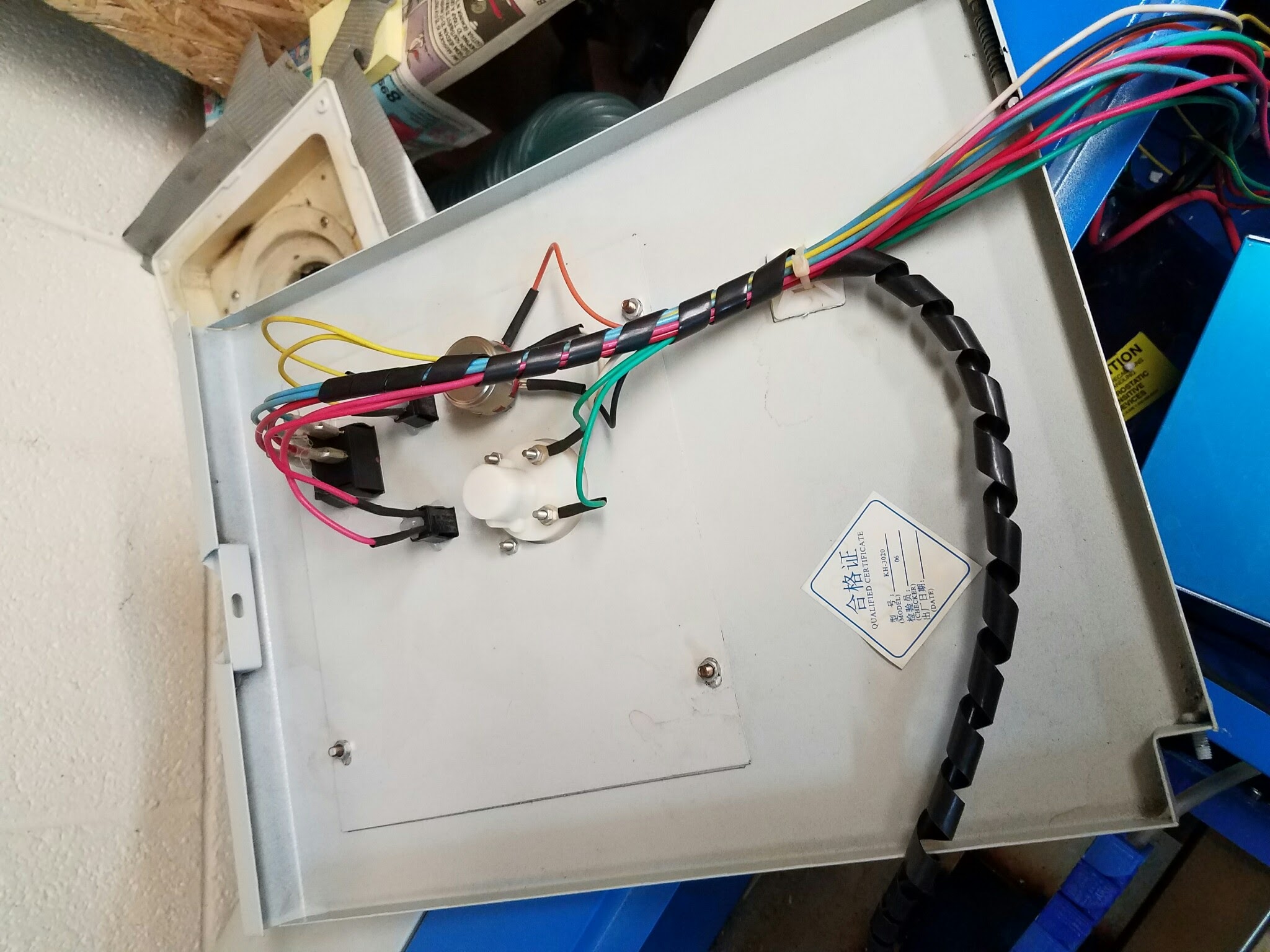
@Bradley_Blodgett can you also post the LPS end of the wiring. Btw I forgot the background. Is a stock machine that broke?
@Bradley_Blodgett ok, sorry for all the questions that will follow. Don’t hang it up yet …I’m not :).
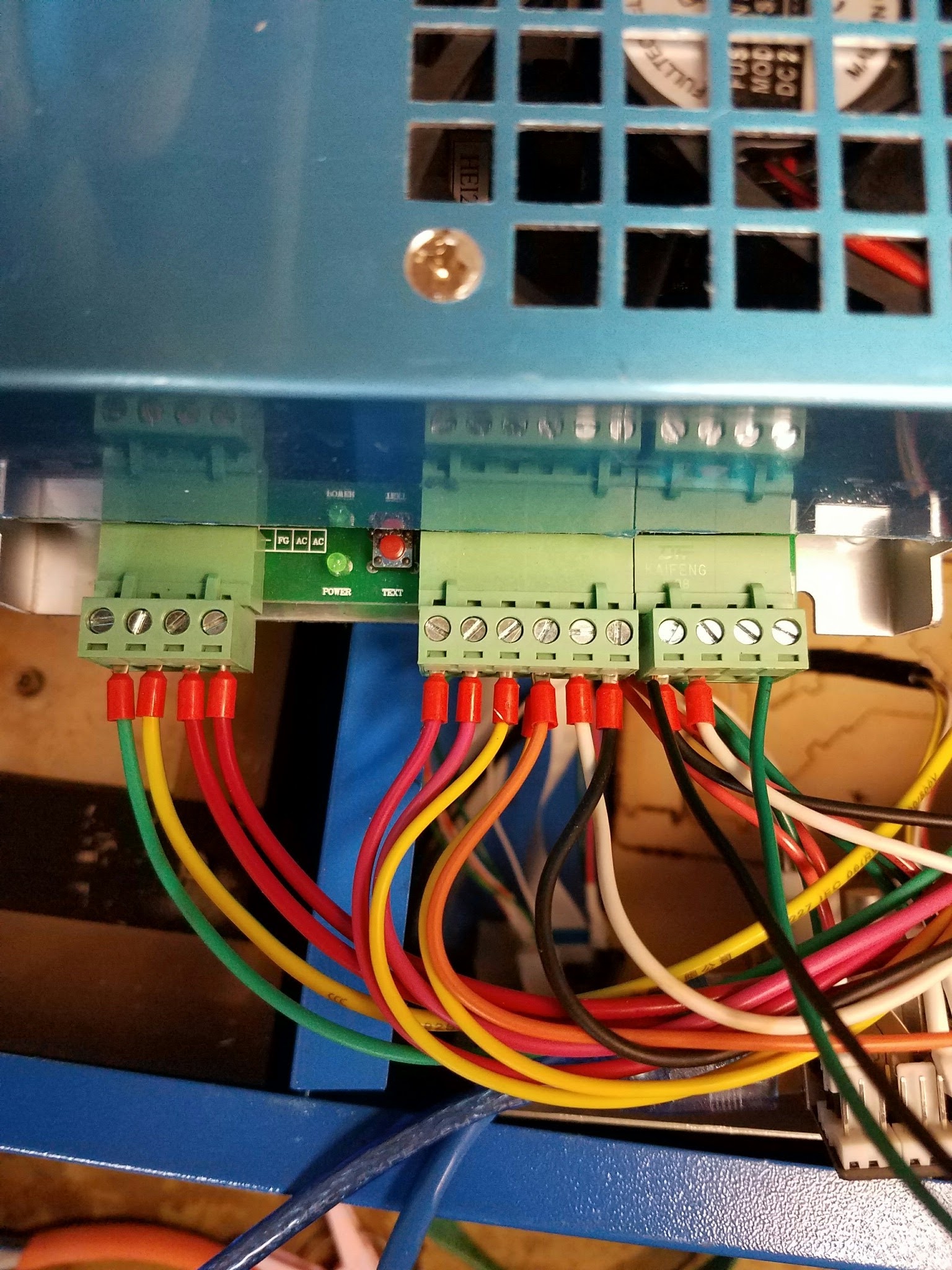
Below when I refer to “Test Sw” insure that the “Laser Sw” is on. Terminals are numbered right to left. Connectors are right/middle/left going right to left.
1.)You have added a smoothie and the laser stopped firing with the test button since that time, is that right?
2.) It worked before you added the smoothie, is that right?
3.) Does the test button on the LPS fire the laser with “Laser Sw” on?
4.) Is the green PWR light on the LPS illuminated?
5.) Where do the 2 black wires on the rightmost connector (terminal 4) connect to?
6.) Where does the white wire on the rightmost connector (terminal 3) connect to?
7.) Where does the black wire on the middle connector (terminal 1) connect to?
6.) Pull off the L wire (green) on the first terminal of the rightmost connector and try the “Test Sw”, does the laser fire?
Hi @donkjr thanks for the response!
If I take a couple steps back I can paint a complete picture. The stock system stopped working last fall. Movement but no laser fire. (No reading on the meter on the control panel) I tried replacing the LPS and the tube with the same results. I decided to replace the last component left which was the controller, and it just made sense to replace it with something more functional like the Smoothieboard.
Fast-forward some months later and I finally got the gumption to assemble the middleman and get everything put back together. I think that answers questions 1&2. Moving on to the rest:
3.) Does the test button on the LPS fire the laser with “Laser Sw” on?
No, just tried that, no activity
4.) Is the green PWR light on the LPS illuminated?
Yes
5.) Where do the 2 black wires on the rightmost connector (terminal 4) connect to?
One goes to the main gound on the smoothie, and the other to the ground for the pwm (2.4) on the smoothie
6.) Where does the white wire on the rightmost connector (terminal 3) connect to?
Connected to main + on the smoothie
7.) Where does the black wire on the middle connector (terminal 1) connect to?
To the Neg on the pot
6.) Pull off the L wire (green) on the first terminal of the rightmost connector and try the “Test Sw”, does the laser fire?
Removed the green wire from LPS and no laser fire on test from the LPS.
Other notes, I am supplying 5v to the smoothie from a secondary atx power supply. Also I have another LPS that I have not tried any of these tests with that is an option if these results don’t add up.
Thanks again for the help!
Ok lets start here:
8). Your power supply should be this configuration:

… is this right?
5.) Where do the 2 black wires on the rightmost connector (terminal 4) connect to?
One goes to the main gound on the smoothie, and the other to the ground for the pwm (2.4) on the smoothie
******************
OOPS, That wire is 24VDC??? If you ground it the LPS will likely not work and may have blown the 24VDC output.
******************
6.) Where does the white wire on the rightmost connector (terminal 3) connect to?
Connected to main + on the smoothie
*****************
OOPS, that’s ground, your smoothie shouldn’t have any power?
I thought you were supplying 5VDC to the smoothie from a separate supply.
The smoothie needs either:
24vdc AND 5vdc
OR
24vdc and an onboard regulator
Look at “Logic Power” under this link:
http://smoothieware.org/laser-cutter-guide
****************
7.) Where does the black wire on the middle connector (terminal 1) connect to?
To the Neg on the pot
That looks OK …
…
NEXT STEPS:
Disconnect all DC power from the smoothie we will deal with that later.
OK. lets pull ALL the wires off the rightmost LPS connector and check it.
Starting from the right set your DVM to DC volts and measure each pin identified below with the black lead on ground.
Turn on the power …
8.) check the second terminal for 5vdc when measured to grnd. Is it?
9.) check the 3rd terminal for 0vdc when measured to ground. Is it?
10.) check the 4th terminal for 24vdc when measured to ground. Is it?
After these tests we will assess whats next.
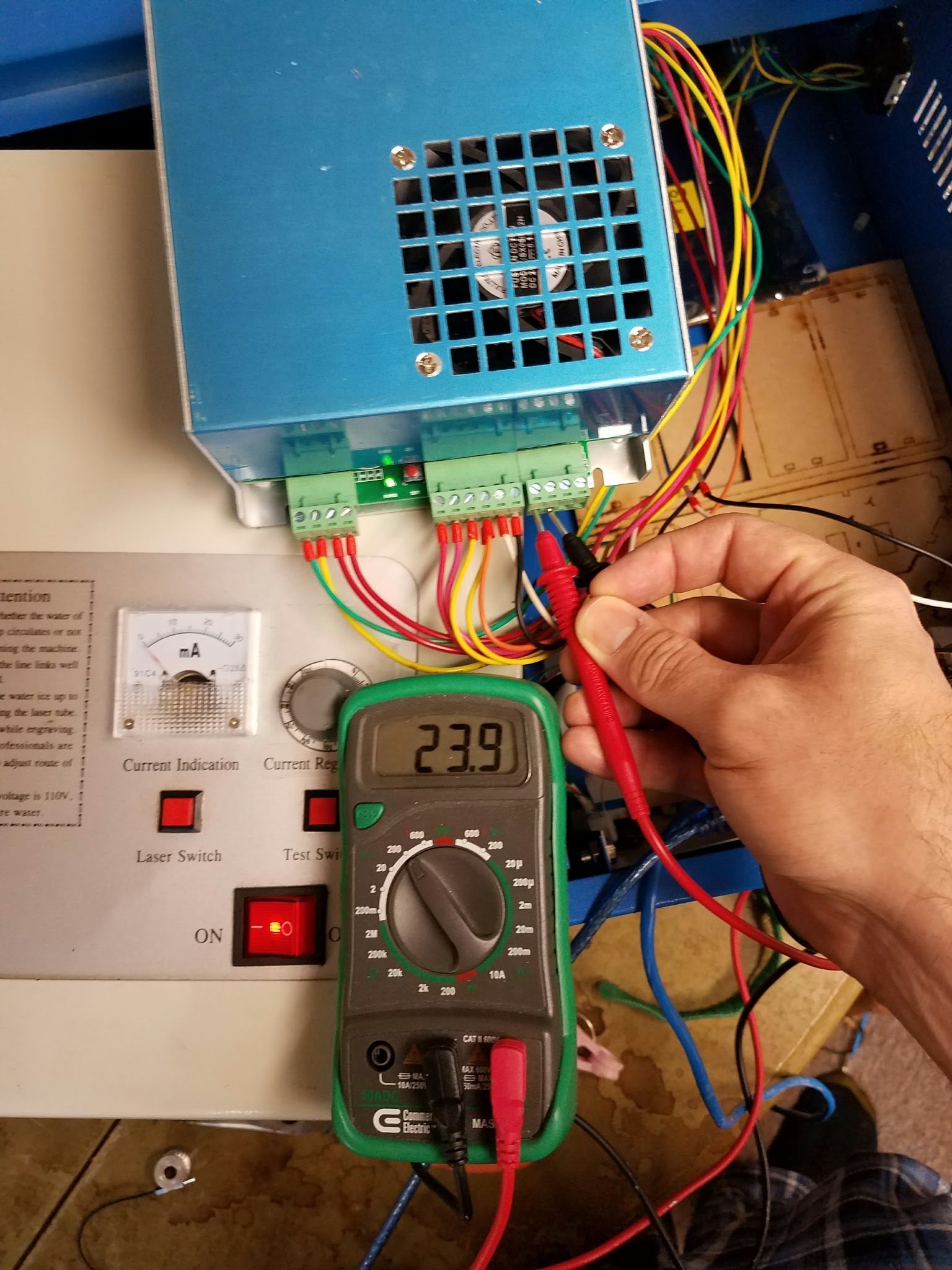
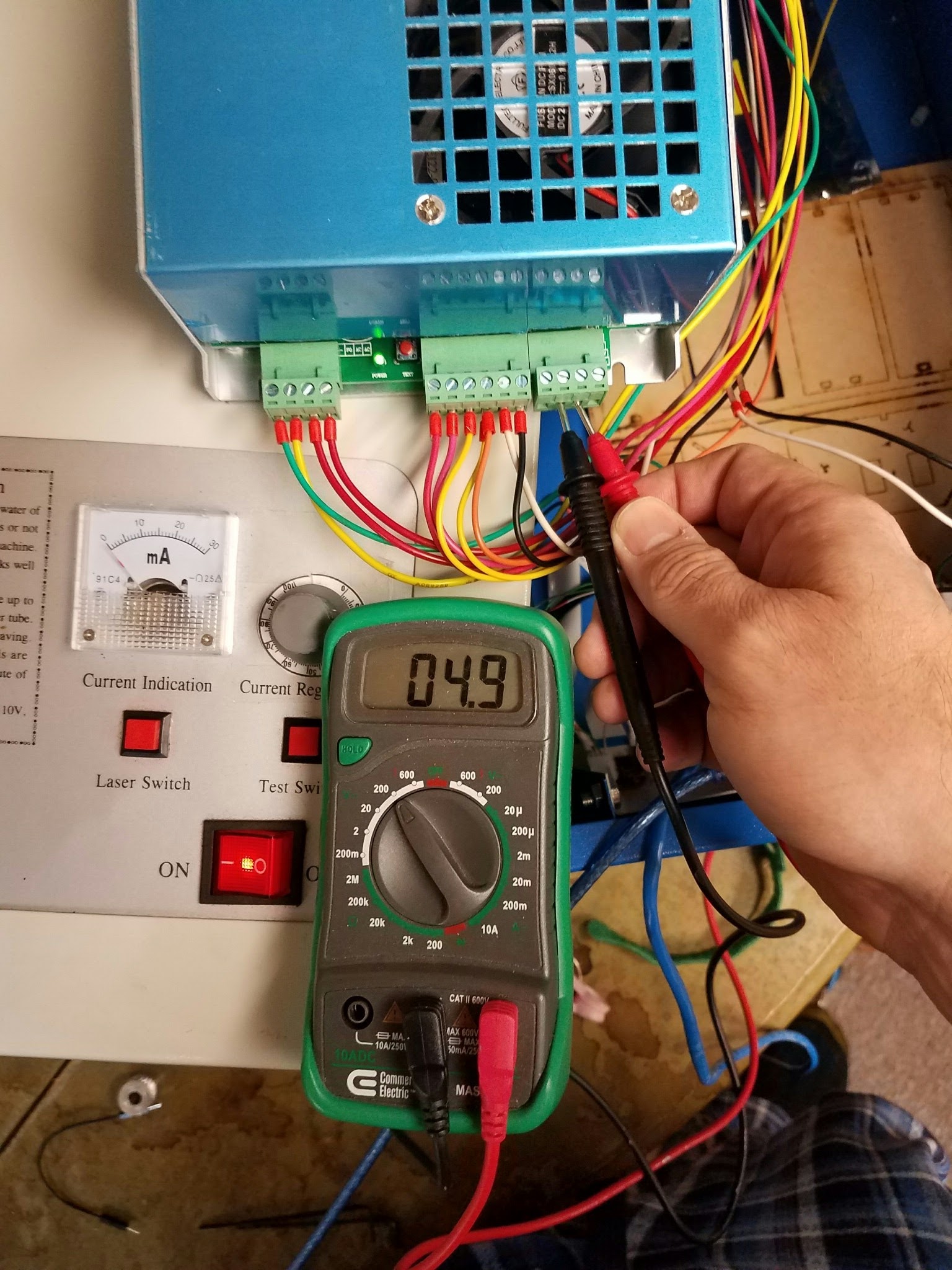
10.) So the 24vdc was connected to ground right?
Leave all the wires off that connector and see if
11.) the Test Switch fires the laser with the Laser Switch on?
12.) the test switch on the supply fires the laser
Yes, that’s correct. I tried the test fire button and the test button on the LPS with no result. I also checked the pot voltage while I was at it, and I get 5v from pos to neg and I get the expected variable output from neg to the yellow (i think) output wire from the pot.
Its helpful if you answer with reference to the question # so I don’t get confused.
I have found that when doing this remote I have to be clear as we cross each step, so sorry for lots of obvious and redundant questions :(.
Lets summarize where we are:
… the 24vdc was shorted to ground
… the 24vdc and 5vdc are still ok
… the laser still does not fire with the local button or the test switch while the laser switch is engaged.
13.) are all the above correct?
14.) did you rewire the LPS?
Now we need to measure the center connector. Don’t change any wiring and …
Starting from the right terminal on the center connector and measuring vdc to ground with your DVM…
15a.) terminal 1: does this measure 5vdc?
15b.) is this connected to one side of the pot?
16a.) terminal 2: does this measure some voltage between 0-5vdc?
16b.) does this wire connect to the center terminal of the pot?
16c.) does the voltage vary with the pots rotation?
17a.) terminal 3: is this terminal read 0vdc
17b.) does this connect to the other side of the pot?
18a.) terminal 4. this terminal should be empty where does the yellow wire go to?
19a.) terminal 5: with the “Laser Switch” engaged what does this read?
20a.) terminal 6: what does this read?
Hi @donkjr , not giving up, but I got called out of town for my day job. I’ll be picking this up Wednesday night/Thursday morning. I really appreciate all of your help on this!
Ok picking this back up where we left off. I’ll start posting answers inline as to not get off track:)
+Bradley Blodgett
Its helpful if you answer with reference to the question # so I don’t get confused.
I have found that when doing this remote I have to be clear as we cross each step, so sorry for lots of obvious and redundant questions :(.
Lets summarize where we are:
… the 24vdc was shorted to ground
… the 24vdc and 5vdc are still ok
… the laser still does not fire with the local button or the test switch while the laser switch is engaged.
13.) are all the above correct? This is correct
14.) did you rewire the LPS? Definitely not, I wouldn’t try something that has a high chance of killing me 
Now we need to measure the center connector. Don’t change any wiring and …
Starting from the right terminal on the center connector and measuring vdc to ground with your DVM…
15a.) terminal 1: does this measure 5vdc? Yes
15b.) is this connected to one side of the pot?yes
16a.) terminal 2: does this measure some voltage between 0-5vdc? Yes
16b.) does this wire connect to the center terminal of the pot?Yes
16c.) does the voltage vary with the pots rotation? Yes all the way from 5 down to 0
17a.) terminal 3: is this terminal read 0vdc yes
17b.) does this connect to the other side of the pot? Yes
18a.) terminal 4. this terminal should be empty where does the yellow wire go to? It connects to the test fire button
19a.) terminal 5: with the “Laser Switch” engaged what does this read? .015 v
20a.) terminal 6: what does this read?0v
I’ll post some pictures inline as well