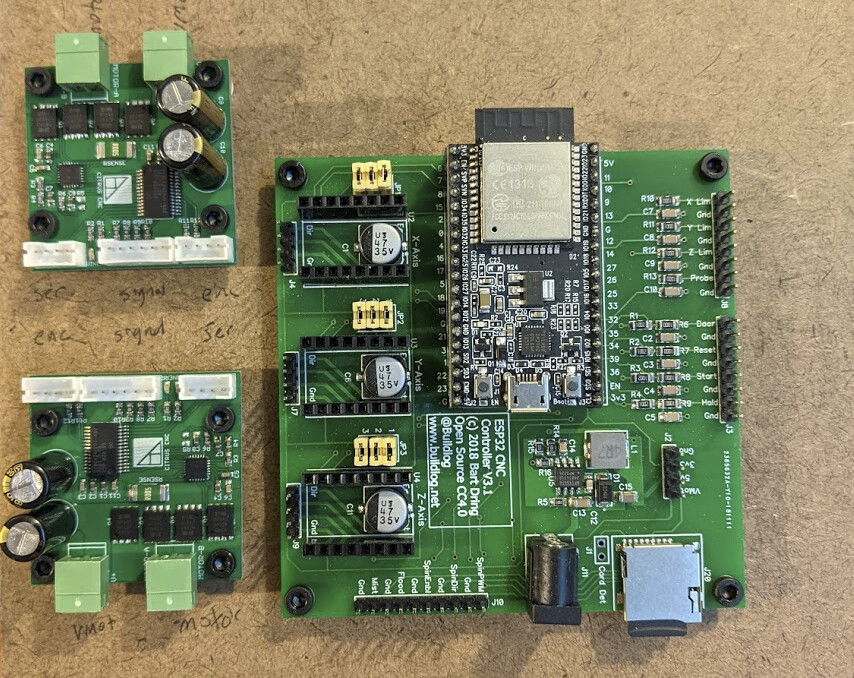
I finally started wiring up the Monocle. I’m prototyping the control board setup on a piece of masonite. I drilled 4mm holes to mount it to the extrusion with M4 drop-in T-nuts. I drilled 2mm holes in the masonite matching the M3 mounting patterns in the boards, and then ran an M3 tap through the holes. It’s good enough to hold a screw in place. Then I cut off ~5mm sections of 1/4" vinyl tube as standoffs. Unusual and unorthodox, but…
With the two Tarocco servo control boards and Bart Dring ESP32 controller board mounted, I wired it all up. The Tarocco boards take STEP/DIR, so I made JST-PH-6 (2mm pitch) to dupont male harnesses for STEP/DIR on one side of the step sticks, and GND/5V on the other, ignoring the rest of the positions. I hooked up X and Y limit switches with a few dupont female connections. I connected the encoders from the servos which required making JST-PH-4 harnesses. I hooked up a MeanWell 24V power supply to the barrel jack on the ESP32 CNC board and each of the servo boards using bootlace ferrules, and connected the motor power wires also with bootlace ferrules. I put a fused C14 plug on the supply side of the MeanWell.
Using dupont, JST PH, spade connectors, and bootlace ferrules meant that I had to use four different crimping tools. This is the geek life!
This wiring looks so ugly that I didn’t bother taking a picture; it’s meant just to let me try out this board. I’m expecting to migrate to a different board soon.
I watched my DHCP server to see what IP address the ESP32 would come up on, so that I could connect to it and configure the system. However, the ESP32 never seemed to request a DHCP address, so I thought I’d look for debug messages via USB. I connected the ESP32 usb port to my laptop, and my laptop screen instantly went black and the fan started going full speed, and the power button did nothing even when I held it down for 15 seconds. This was scary; this is a relatively new laptop, only two years old, and I really really don’t want to buy another one… Fortunately, the reset button worked and the laptop is back, but now I’m reconsidering my choice. I think I need to pull the ESP32 dev board out of the carrier and take this one step at a time. And maybe I’ll connect it to a different computer first.
My hope was to quickly get to running gcode just to move the X and Y axes, but that’s looking less likely now.
Having calmed down a bit, I powered the board back on and poked around with a multimeter. I measured 4.9V on the 3.3V bus, which is provided by the ESP32 board from a 5V supply. When I remove the ESP32 board, the 3.3V bus has no power. Either:
The 3.3V LDO on the ESP32 board is fried, or
One or both of the servo boards is feeding 5V down what are supposed to be its STEP/DIR input data lines, or
Something is mis-wired, or
Something is mis-labelled.
With the ESP32 board removed from the CNC board, I connected it via USB to not my primary laptop this time and it survived and showed LED activity, and the USB host controller seemed to work because a /dev/ttyUSB0 port showed up, but when I went knocking with minicom, no one was home. So whatever happened, I think that dev board is probably toast.
I have a loose BTT SKR MINI E3 V1.2 with a blown TMC driver that was installed on my corexy before the TMC driver blew. I don’t need the drivers at all for this application (two servos, one external stepper driver eventually), and the V1.2 has STEP/DIR headers I can pick off; I just need to rebuild the firmware. I don’t think remora supports it, but klipper does (and I should be able to comment out the tmc2209 support from the config file. And they mention laser support. Just need to break out the rPi 4. That might get me unblocked for now.
To use klipper, I followed the default easy path of starting with putting octopi on my raspberry pi and installing klipper on it.
The 64-bit build of octopi didn’t boot, but since I don’t have monitor and keyboard set up, I wasn’t eager to test, so I just tried the 32-bit build. This is only a 2GB unit anyway.
While looking at configuration, I see this warning about current status of PWM:
There is a limitation of how frequent PWM updates may occur. While being very precise, a PWM update may only occur every 0.1 seconds, rendering it almost useless for raster engraving. However, there exists an experimental branch with its own tradeoffs. In long term, it is planned to add this functionality to main-line klipper.
Fortunately, my first plans involve cutting and vector engraving at a constant power, so I think this limitation is OK. But this might be a reason to get a remora-capable board and follow @dougl’s lead to LinuxCNC and remora.
Before I hook this up, I want to test whether 5V is leaking out STEP/DIR on my servo controller boards because I don’t want to fry another board. It turns out that the servo controller logic voltage can be as low as 1.8V so I can just feed it with 3.3V instead of 5V. That was a miss on my part in the first place.
It was a mistake to start with servos, I think. I should have started with steppers and upgraded later. But at this point that would be a lot of mechanical changes so I’m going to throw good time after bad and try to get this working in this configuration first.
I’ve now found the klipper discord so I can ask questions. I didn’t find it in the docs (it might be there and I just missed it) but it was offered when I tried to open an issue for a missing configuration file for PWM control as needed for a laser.
Pretty crazy how things we think are ‘just a quick setup to test’ find ways to make it not so quick…
The ESP32 have been pretty solid and so are Barts boards but this 5V tolerance stuff has got me a couple of times. A quick way with 5V tolerance could be an Arduino running GRBL but I’ve never setup servo’s on it but I expect it works since many used servos with probes.
One of the things I was impressed with about Remora was that ScottA had already enabled encoder support in it and was himself using the $15 magnetic encoder boards on the back of his steppers. Closed loop motion removes lots of issues seen by open loop systems.
I should have looked before hooking the servo control boards up to 5V on the stepstick output. I had 3V3 available and just didn’t check whether it was OK to use.
My servo control boards take STEP/DIR and take encoder feedback from optical 1440ppr encoders on the servos.
I lose again. Finally realized that what I thought were external stepper headers are VREF / CLOCK / INDEX / DIAG and don’t map to pins. To get to STEP / DIR I’d have to solder to small pads.
Now looking for other unused pins here and there to see if I can find enough pins to repurpose. If I quit trying to use the display, I think there are enough pins available on EXP1 to use those instead for data, and there’s 3V3 on the SWD header.
what board are you using now? If it has stepper motor sockets… ok, you no doubt know this so it must be a board with built-in drivers. Shame they didn’t break out the step/dir to headers. Good luck!
Yeah, using a BTT SKR MINI E3 V1.2 with at least one blown 2209 (Marlin complained). I have once gotten one servo axis to move, and then it kept trying to drive it through the limit switch; gotta test that. (With my luck I blew a MOSFET on the driver when the limit switch failed, but it’s supposed to have built-in protection and not need a RED added.)
But I’m thinking that spending $50 or so on a better board might make sense… Here are some possibilities in that range.
The Octopus explicitly calls out Klipper support. I ordered it for that reason. I’m guessing that Klipper support means it’s likely to be easy enough to support in Remora at some point, but also I could do a switcheroo with my MKS sbase if I needed to.
The Octopus uses an STM32 and Remora runs on the MBedOS platform which doesn’t yet support STM32. We’ve been sticking with testing LPC1768 and LPC1769 boards. I think that means any of the Smoothie based boards. The SKR v1.4 and v1.4turbo are the easiest to support and have replacable drivers. TMC2208 and TMC2209 are currently supported with TMC5160(?) in the pipeline.
I “like” how the BTT SKR 2 calls itself “SKR V1.4 Turbo” in the description, then, since it has a STM32F407VGT6 processor.
Looks like this would run Remora:
But when I’m using only external drivers, buying 5 2209 stepsticks that I’m not expecting to use is annoying, and I can’t find it bare. Not even on aliexpress…
I’m curious, though; MBedOS looks like it supports the STM32F446ZET6 on the Octopus — am I missing something? It’s explicitly listed in supported debug tools at Mbed — PlatformIO latest documentation and if I grok the naming convention right this is the target:
Similarly for the BTT SKR 2 with the STM32F407VGT6:
Not saying that makes Remora magically support either. I see #include "LPC17xx.h" and I’m sure more work would be needed. But is it actually related to MBedOS support?
The Remora git repository is certainly unusual in having multiple mercurial repositories checked into it.
Yes, I’m running the SKR v1.4 turbo with the LPC1769 chip and so is Scott Alford.
doh, I forgot that it was/is the DMA package Remora is using which only supports the LPC1768/69 chips. Scott said he’d like to see it on the STM32 at some point but it would take some effort in that DMA area which is key to how it works now.
It looks like the servo drivers I’m using go into fault any time they move a substantial distance. I backed the tarocco on crowd supply a couple years ago and then changed gears before my shipment arrived, but about the time it was released it became apparently abandonware and the documentation is terrible, and after it arrived I discovered that this “open hardware” requires a janky proprietary windows development system to update the firmware, which was a rude shock.
As far as I can tell every time an axis moves more than a few mm it faults. I’m using the servo and driver that shipped together as a unit, but I’m deciding it’s junk.
Time to design some new mounting hardware that will mount some stepper motors and quit mucking around with these servos. They seemed like a wonderful idea but now I’m less enthralled.
That was pretty much a waste of a perfectly good Saturday.
Canceled (I hope) the Octopus that was going to arrive Thursday. All the 1.4 Turbo boards available wouldn’t arrive until even later than that. Placed a new order:
This has an LPC1768 and can run Smoothieware, so it should work for either Klipper or Remora.
Tomorrow I’ll modify things to work with stepper motors; I’ll have to do a bit of redesign to one (I think) printed part and run new wiring.
That should work well. I know nothing of the TMC2130 but they are socketed so Bob’s your Uncle. And I agree that it sucks you have to pick drivers and can’t just get the board. Conside how I thought the TMC2208 was good enough because I didn’t need the extra current of the TMC2209 so I have 20 of them. Now I learn that they have issues and I had to turn off Stealth Chop on my extruder motor because it was having issues and it’s a known problem which the TMC2209’s don’t have.
I looked into Klipper when I started down putting LinuxCNC/Remora on all my machines but found out while it was similar to LinuxCNC/Remora in the separation of realtime/Trajectory planner it was still just for 3D printers. I knew LinuxCNC/Remora would work on CNC’s and Scott has 4 years running his 3D printer so they only question was laser cutters and I figured that’d be the easiest. I’m still working on getting raster engraving working and cutting is the easy part. I expect over the years ahead they will expand what Klipper supports so long as they keep at it.
That board ships with either 2209s or 2130s. I would have bought the 2130s because they are specified for 2.5A whereas the 2209s are specified at 2A, but that would have delayed delivery, so I got 2209s. (Not sure that the stepstick format makes that much sense even for 2A let alone 2.5A so it might be a distinction without a difference.)
Now that I’m going to change from servos to steppers for X and Y, I’ll actually use two or three of them. (I plan to add an A axis at some point.)
Found a couple of these I bought years ago for a project I abandoned. 2A, so maybe a fan pointed at the heat sinks on the drivers would be a good idea…
I figure that the laser head is similar in mass to a printer hotend, so I probably need less than 1A for X. Y, on the other hand, has to move 1.5 meters of 2040 and MGN12 rail so I’m just hoping 2A is enough.
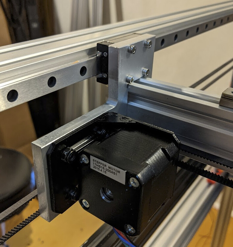
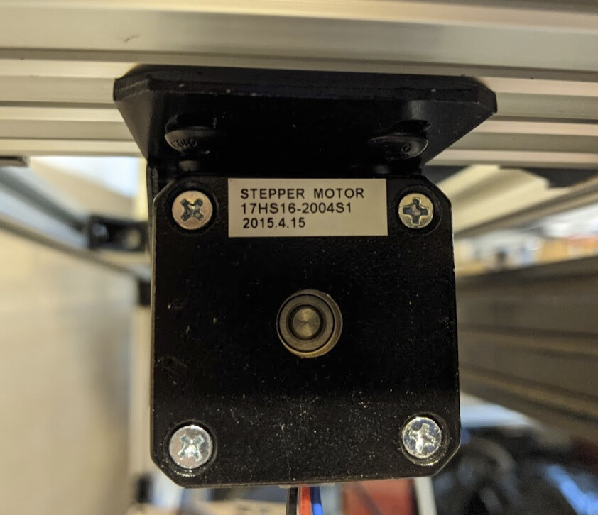
I made a new left gantry mount out of 8mm aluminum stock. Now almost all my X gantry hardware is aluminum rather than plastic; I just have a few belt clamp pieces still printed. No need to replace them; they are working fine. The new gantry mount has slots to mount a NEMA17 angle mounting plate, such that the shaft is in the same place as the servo shaft previously was. I do need to re-route wires. I’ll have to disassemble the dupont connector at the end of this 1M integrated bundle to feed the wires through the drag chain.
I got it roughly positioned, then was able to snug one screw just barely enough to hold it in place while I slid the motor out of both the pulley and the mount. Then I made sure the mount was square, and tightened all four screws holding the mount to the shelf. With that fixed in place firmly, I slid the motor back in, shaft going through the pulley, then put the M3 motor mount screws through the face of the mount into the motor, and then finally aligned and tightened the pulley on the shaft.
This view lies; you can’t actually tighten the mounting screws near the back of the motor.
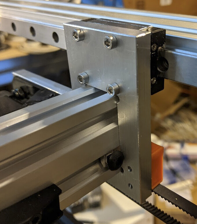
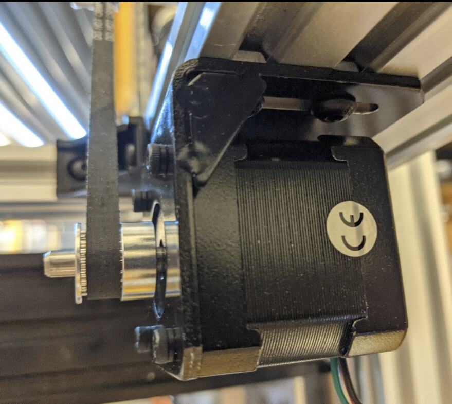
This view shows why. What was amazing was that I was able, with a ball-end hex wrench, to tighten one of the front screws enough to keep the mount steady for disassembly.
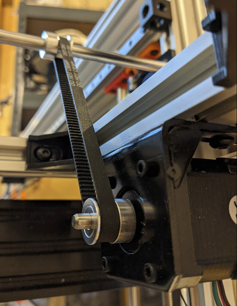
The belt is tight but not over-tight, and I now have the physical part of my X/Y motion platform back.
I stripped the outer sheath from some stranded 28AWG ethernet wire, and selected a pair to use for the limit switch. I removed the dupont housing from the X motor cable. Then I was able to pull the four stepper motor wires and one pair from the ethernet through the cable chain. I terminated the ex-ethernet pair with bootlace ferrules. I stripped about 1cm of wire, folded the wire over the insulation, and then chose the smallest ferrule that would fit over the wire and insulation. This seems to work well for wire too thin to be securely held in the 0.5mm smallest ferrules I have. I made sure that the folded-over wire was fully inside the ferrule so that it wouldn’t be broken off.
Next I need to make an “extension cable” for the stepper to reach from the fixed end of the drag chain to the control board.
I discovered that the e-stop button I have is missing a nut, so I ordered a new estop-in-a-box from Amazon. I want it in a box because I need to fasten it to the outside of the frame. I made this with only one frame, rather than an internal and external frame, maximizing the amount of space inside for the mechanism, but there’s no obvious place to mount an e-stop in the mechanism. I have the computer on a shelf mounted on the side, and I’ll mount the e-stop near it by 3D printing a shelf for the box to sit in.
@dougl Does linuxcnc need to run on a RT kernel if it’s controlling a remora, or do all the time-sensitive bits run on the remora, like with klipper? I was thinking of running motion planning on the laptop if at all possible, reserving one of my rare (for now) Raspberry Pis for other purposes.
I found dwrobel/linuxcnc Copr so hopefully I’m OK if I need the RT kernel on the control laptop running Fedora