My machine has a problem with the top right corner, the beam target is worse the more the head approach to that corner. It deviates in the same way as if the Y rails where not leveled.
They are parallel one to each other, and I also measured the level between them placing a level tool over the gantry as I move it all over the Y length. But in practice I need to push the right rail end down to make the target coincident with the other corners.
As the mirrors are fixed to the gantry, when I change the right Y rail height at the rear end, the beam ends up targeting a lower and more to the left point than before, which is what I exactly need.
One should say that’s the solution, but no, because I would need to change the level much more than the allowed by the gantry before it starts getting stuck. Because when the rails start being not leveled, the distance between end points get larger.
So there must be another variable here I can’t figure now what is, making the the beam misaligned on the right top zone of the machine.
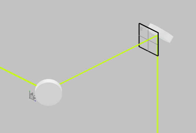
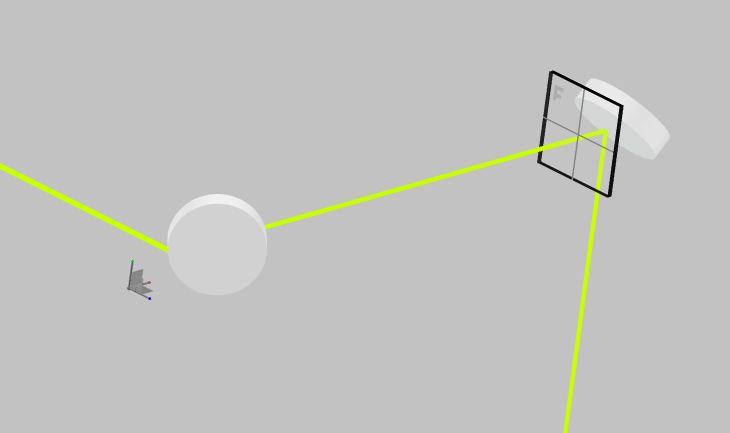
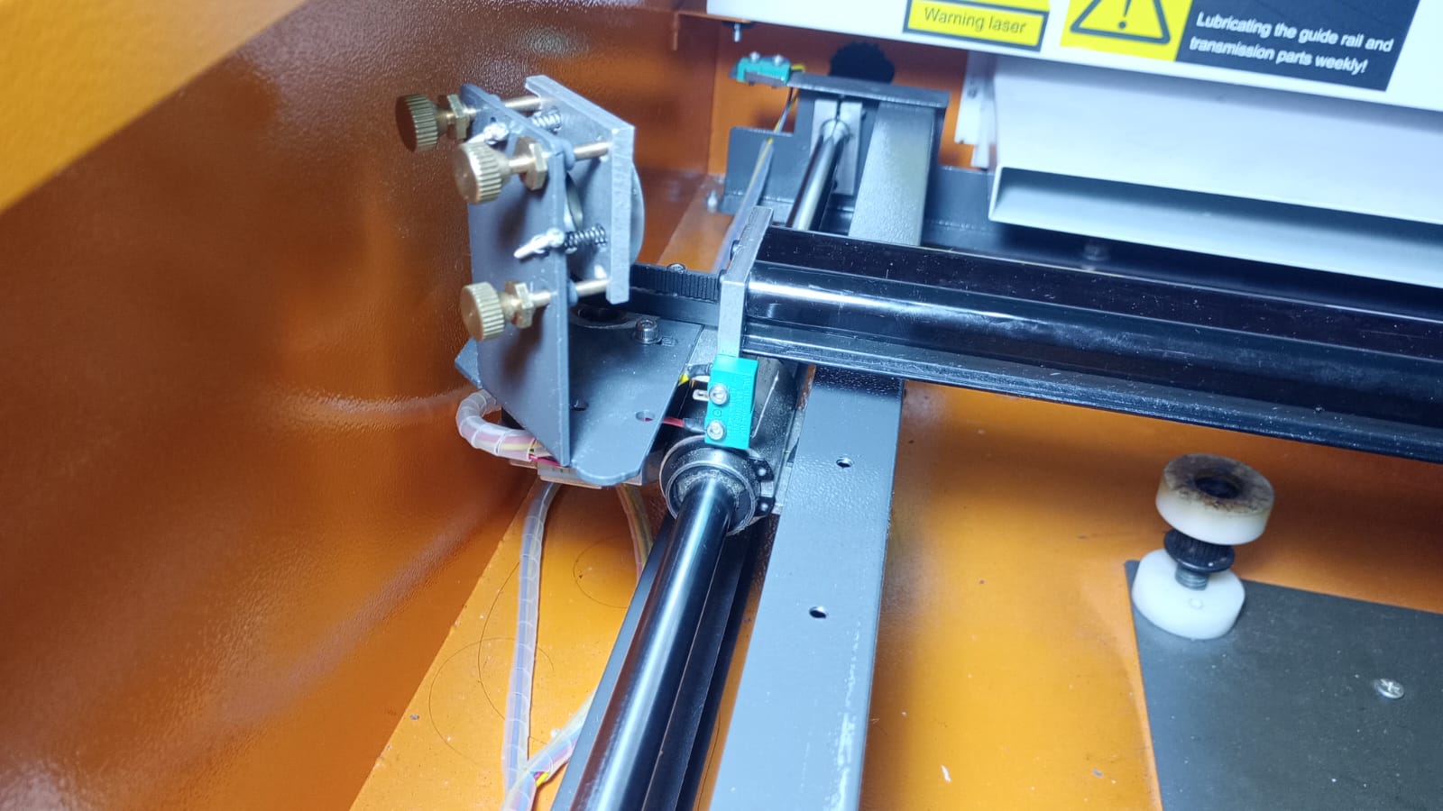
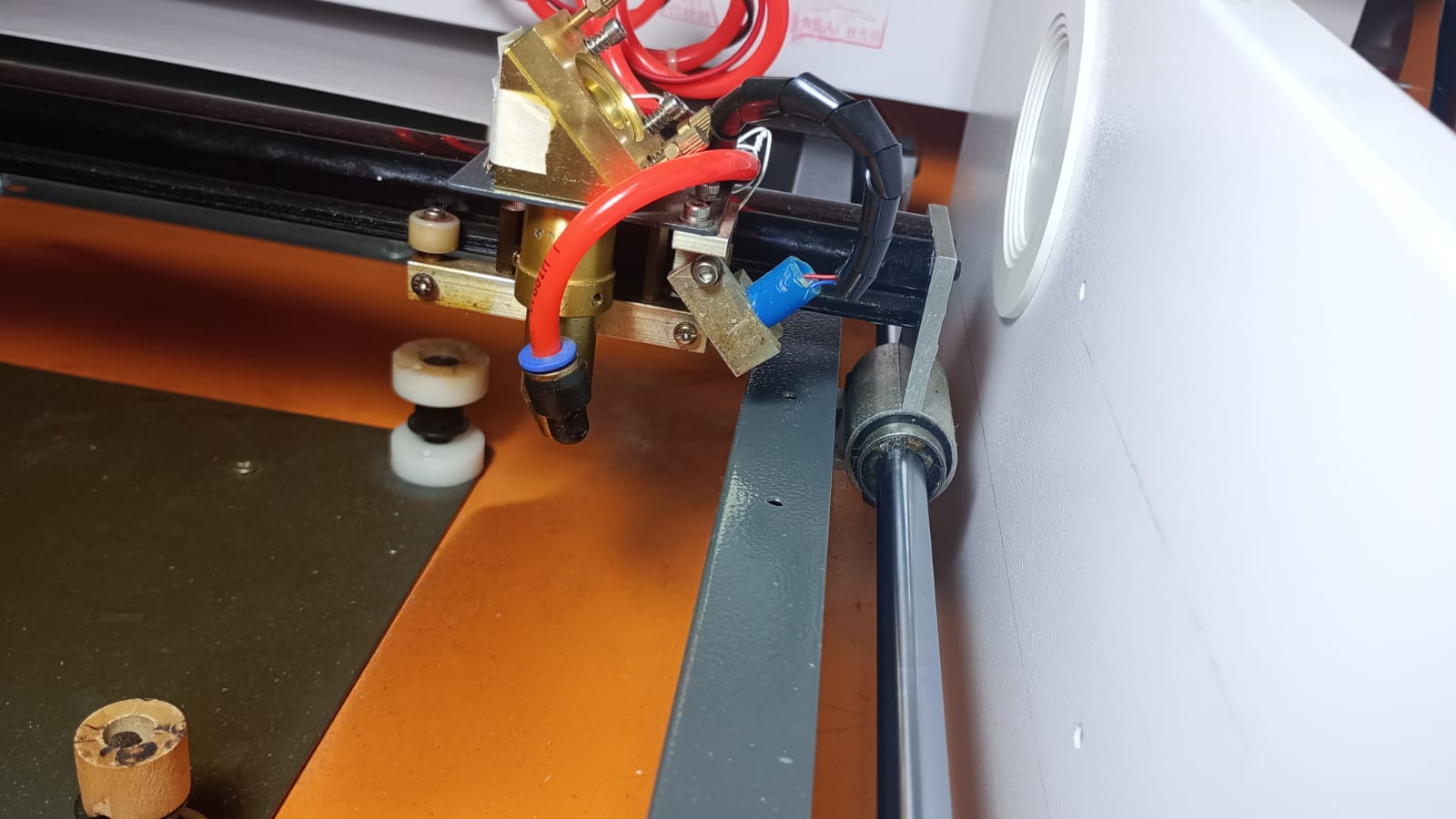
Here are two images showing how the beam changes direction when rotating the gantry, with the rotation axis being near the 2nd mirror. You can see in the 2nd image, when the 2nd mirror is facing a few degrees down the target changes to be lower and more to the left.
I took the level measures to avoid that. So I don’t think so. But I need to twist them like this in practice to make the machine to work properly, that is why I’m confused.
I take the level on both ends like that and the bubble is in the exact same point in both places.
Light doesn’t lie. Laser levels are a thing for a reason. So there’s obviously a mechanical defect, right?
Do the orthogonal axes also both measure the same?
Also, that’s not a precision level. I’m not being facetious; that level really might not have the precision to demonstrate a problem.
What you really care about is tram — the extent to which the machine’s orthogonal axes are indeed mutually orthogonal. As a hobby machinist, the only place I use a level to establish tram is on my lathe, where I use a master precision level and calibrate it first on a surface plate, and use that to adjust the lathe bed to not be twisted.
But on your machine, you have a built-in laser system to measure tram, and incidentally to cut/engrave… If your mirrors aren’t twisting as you move the axes, then the laser moving is measuring that your machine isn’t sufficiently trammed.
Could be something as silly as a warped rail, or loose eccentric that is only subjected to a twisting force in that corner (say, interference from the air assist hose).
I think it’s enough to see the bubble keeps being in the middle all the way through too know the level is almost perfect between rails. In case of some fraction of millimeter of error I don’t think that would be responsible of 4mm in distance between the target mark of that corner with the other 3. Or does it?
And as I say. I can kind of solve the problem by twisting the rails a lot, to the point that the gantry can’t move freely. How is that possible? I mean, how can it be better aligned with the levels being clearly not trammed?
BlockquoteDo the orthogonal axes also both measure the same?
I meant measured by the level, not their length. Inasmuch as the level is sufficiently sensitive, do they show the same reading when resting on each of those rails?
I don’t completely understand where all you are taking measurements.
I just know that light doesn’t curve around meaningfully at this scale; there’s no gravitational lensing at work.
I’ve seen this before in a Russ Sadler video on alignment. He mentions the 4th corner issue and made a minor change at m1 to correct for it. I can’t remember how far off it was, but it’s a cheap procedure to check it out.
yes they are at same level.
Recently I realized that the fail start happening from the half of the Y rail.
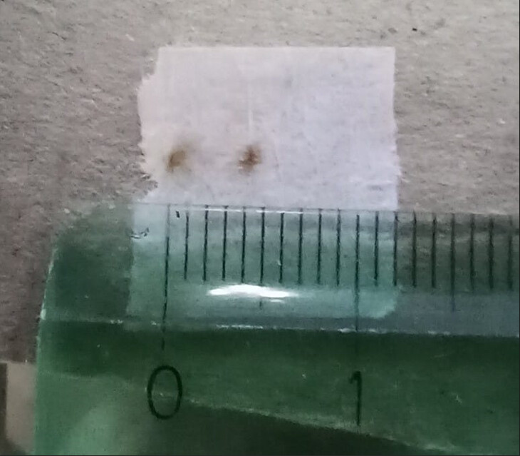
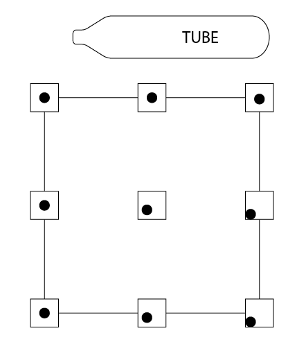
the maximum error can be seen on one of the right corners, depending on which one I chose to align with the 2nd mirror, in this case I aligned the right top corner so the bottom right shows the error. But the strange thing is that the target mark at the half way is the exact same point as the one in the bottom right corner. so there’s no variation from one position to the other. From there, it gradually variate to the target mark on the right top corner.
Could it be a bent rail? In that case, how can I rectify it?
I’d still start by looking for something loose. Eccentric wheels, mirrors. Does the carriage have any play? Does the gantry have any play? I would disconnect the air assist hose temporarily and see if it is any different.
This is not advice: If none of that found an obvious culprit, I know that I personally would disassemble it, taking pictures or video to make sure I could put it back together, and check the individual parts, for example checking the rails against a known true flat reference. That doesn’t mean it’s the best thing to do, just what I’m sure I would do regardless of whether it was a good idea…
I have loosen the rail to make it possible to spin it by hand while the machine is on. And it’s clearly bent. I can see with a naked eye how the 2nd mirror swing while I spin the left rail. And the final target mark changes too. The target mark is actually going down and then up again way through the rail… Now I’ve set it in a way the error is less noticeable but it still there and it’s big yet.
Is there any way to rectify the rail?
I’m guessing this isn’t a new machine so you can’t ask the manufacturer for a replacement bearing rod. I would expect those to be quite inexpensive on both Amazon and Aliexpress. That’s what I would look to do,ie swap it out for a new one.
If that’s not the case then I would do much like you have done but find the bow, rotate it to the top of the machine, mark the position on the end of the rail, locate the max/center of the bow and using a wooden block gently try to remove the bow by flexing in the opposite direction. At that point the bow should be far less so rotate it so the bow is horizontal, inline with the other Y axis rod. This means there won’t be any vertical deflection of the X carriage and the beam should keep true unless the bow now pulls the X axis horizontal.
Oh good, that’s easy! Typically called Linear Motion Rods,Linear Guide Rods, or Optical Axis Rods.
You just need to measure the diameter. Calipers should be sufficient.
Be aware that both metric and imperial standards exist. 6mm, 8mm, 10mm, 12mm, 16mm, 20mm, 25mm, 30mm, and 35mm diameters are common; I’m guessing those are 10mm or 12mm. But also 5/16" is just barely smaller than 8mm; my first 3D printer shipped with 5/16" rods and 8mm bearings and was very sloppy and it took me a long time to figure out why. Similarly 1/2" is 12.7mm.
These typically have a fairly hard outer shell for wear (they are case hardened) and are made from bearing steel (a hard, high carbon, chrome steel). The easiest way to cut them to length is with an abrasive disk. Make sure to leave no burs to damage the bearings; you typically want to chamfer the ends to make them easier to run through the linear bearings that run on them.
If you hadn’t noticed, you can get another few cm of travel in the Y direction by pulling out the exhaust duct in the back and cutting off about 10cm. I think I even got another cm in the front by cutting 1 cm off the rubber stopper on the left linear rod. you might have bumpers on both of your rods. My K40 only has one linear rod which is on the left side and the right side runs on a wheel which rolls over the frame.