So I have an old device which has an Adafruit LCD shield and it’s a 5V device with an LCD, some buttons and a MCP23017 I2C interface to it all. The ESP32 is a 3.3v device and the Arduino Pro Mini I’d used is a 5v device so to get the I2C interface inline to connect with the ESP32, I was thinking of putting 2 10K pull downs on the SCL and SDA lines to take the 4.7K → 5V pullups down to 3.4V.
Does this seem sane?
There’s another device I will be putting on the bus and I will remove its pullups and I know it already works at 3.3V.
I’m still a bit fuzzy on what to do when I have one I2C bus and I have a 3.3V system, one 3.3V sensor and one 5V sensor. I figure I have 2 options on this one:
float the pull-ups on the 5V part and make sure not to put the I2C bus in highspeed mode(driven) and let the 3.3V pullups of the other sensor do the work.
add a 5V->3.3V level shifter on the 2 I2C lines of the 5V module.
But in my current situation, using the ESP32 which has 2 I2C buses so I can put the 3.3V sensor on I2C bus1 and the 5V sensor(with the 10K pull downs) on I2C bus2.
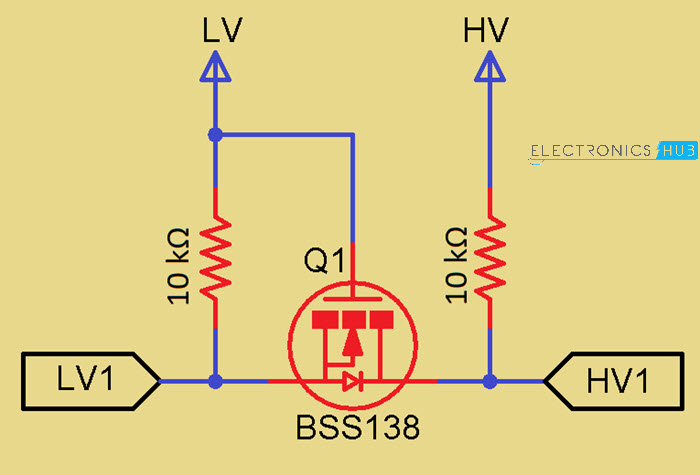
Looking at the spec for the MCP23017 chip, it seems input H is 0.8*VDD which would be 4V when powered by 5V… So in theory, putting pull-ups on SDA/SCL to 3.3/3.4V should not work but in practice it is working. So I should be using level shifters of some sort(chip or transistors).
Since I2C is open-drain( only actively pulls signal down ) and what I have is working(for now), ie my 2nd bus device( the 5V LCD display/button module ) options could be to either lift the 5V leg of each pull-up resistor and bring 3.3V from the ESP32 over to them or get the pull-up voltage into acceptable range for the 3.3V ESP32 and adding the 10K resistors from SDA/SCL to ground can do that. Acceptable esp32 input voltage is VDD+0.3V and max VDD is 3.6V so 3.9V is the input pin max voltage for the esp32 and the 3.4V of the 5V->4.7K->x->10K->Gnd divider circuit is within range.
If I had to put it on the same bus with another 3.3V device I would definitely go with the level shifting.
Been following… Don’t know if you’ve looked at this type of bi-directional interface… I assume data is going both ways… Takes about 6 components for sda/scl. I’ve used this before… it’s from
Currently all the SDA/SCL pullups are already on the 2 devices so grabbing 2 10K resistors and soldering one end to a common ground and each of the other ends to the SDA and SCL side of the pull-ups was quite a simple task.
I’m also going from an Adafruit ATINY85 Trinket to an ESP32 D1 Mini plus another relay and 2 of these drivers for the relays while trying to do it in the same case.
I had made a little timer device to turn our HVAC fan-only on for varying intervals of 5 minutes per button press. Our existing thermostat only has 3 daily temp settings so in the AM going from 60F to 69F just heats the room air way too much for comfort. I want to stair-step the heating process so I’m creating a Thermostat out of an ESP32 and I’m hoping to shove it inside the existing Fan-only control box since I also want it to have that same feature too. I’m using Omron G5V-1 relay already for the fan(HVAC-G) and will add a 2nd relay for heating(HVAC-W). Doh, I just realized I now either need a switch to change from heating(W) to cooling(Y) or I need another relay and 5v driver circuit… Once again, ‘talking’ about this helps me figure out bugs in my processes.
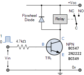
![Relay Switch Circuit]
And I just realized that my Thermostat setup is only setup for heating so a cooling mode needs to be added along with the hysteresis. And possibly it’s just a switch to change the hysteresis direction.
What I ended up doing, after learning that the I2C bus drivers are open-collector types, was to use a poker pin to get under the resistors of the Adafruit LCD button assembly and pulled off the 4.7K pull-ups. This is the 5V device. I then put the Adafruit LCD Button device on the I2C bus and then chained the HTU21(temp/humidity) sensor which has 10K pullups to 3.3V. Seems to be working.
for the relay driver I used this design using an NPN 2n2222 transistor.