My wife, a mathematician, wants to keep track of what she spends her time on, and was inspired by Fred Brooks’ time-tracking clocks:
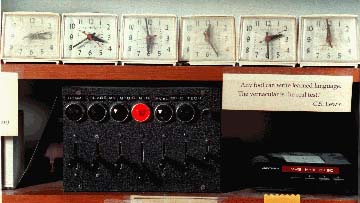
She saw that there are time-tracking cubes available that connect to your phone and have apps that log which of the six faces is up, so that you can keep track of up to 6 different tasks. But she had a problem. She had at least nine things she wanted to track, and any mathematician worth her salt knows that you can’t stuff nine pigeons into six pigeonholes. And she wanted to track her time in google sheets where she could easily do her own analysis, not in a cell phone app.
The simplest platonic solid that has at least nine faces is a dodecahedron, so she thought a time-tracking dodecahedron would be great. Could I make her one?
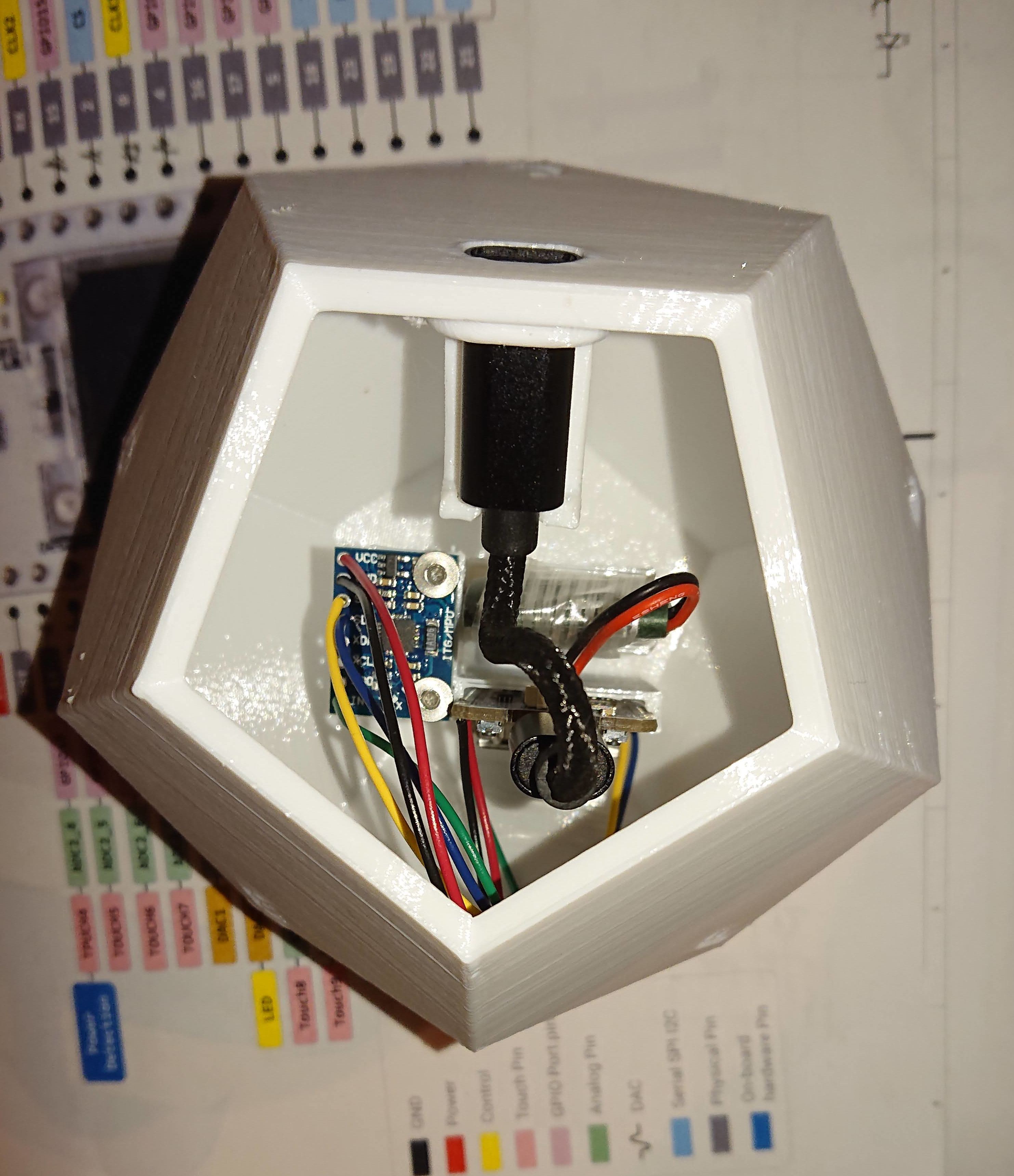
Perhaps rashly, I said that sounded easy enough. 3D print a hollow-shell dodecahedron with a removable lid, put an accelerometer, single-board computer with WiFi, charge controller, battery, and inductive charging pad inside, a few lines of code, and hey presto the project is done, right? Right?
Yes and no.

-
The simple way I first thought of to design the shell in Solidworks wasn’t supported by Solidworks — its 3d sketches have significant limitations. That said, despite running into multiple limitations in Solidworks, I think this project was easier than it would have been for me in OpenSCAD or FreeCAD. I do lots of my work in OpenSCAD, and most of my CAM in FreeCAD; I’m not knocking either of them.
-
The MCP6050 MPU I selected, and which is widely available, is only partially documented, and the ability to raise an interrupt when it quits moving is available but undocumented.
-
The inductive charging pad I bought didn’t work. This was a blessing in disguise because making it fit would have made the device too big to comfortably fit in the hand, and the seller promptly and apologetically refunded for the broken device, so no hard feelings. This allowed me to go from 60mm long edges to 40mm long edges, so now it’s comfortable to pick up. It wouldn’t have been comfortable with edges half again as long.
-
I bought a USB-C to micro-usb adapter cable and made a slot in the side to hold it (the end is the black oval slot in the picture above), but didn’t think about having any features inside to keep it from being pushed through the shell. (The cable I bought stuck in the SBC, but none of the reviews mention this as a problem, so I think it’s a unique sample error, and honestly in this case it’s almost a feature instead of a bug, because once the case is snappped together it’s hard to get apart, and if it fell out of the SBC it would be very inconvenient.) I added a catch in the second revision that I haven’t printed yet.
-
My first try at the design had a really stupid way of trying to hold the battery and SBC in place with angled surfaces and VFB tape.That was crazy, I discovered when I printed it. Hopefully the second try, with slots to insert them into, will work better, because it’s about 200g of PETG for a single print.
-
Documentation on the Heltec ESP SBC I bought is scarce and conflicting; they redesigned the board without changing part number or public schematics, and it took experimenting to figure things out. Some things never worked, like measuring input voltage to know whether it is currently charging. A lot of of their sample code didn’t work out of the box.
-
Between Heltec not having a lot of documentation I could find and Invensense having removed half the functionality advertised for the MPU, I never did get motion interrupts working, so I’m just waking up every 10 seconds to find out whether “down” is a new direction. This uses more battery than I hoped.
-
The 1000mAh LiPo cell I bought has low-voltage protection that cuts off at 2.75V, low for maintaining long cycle life. Because of that, I’m turning off the timer and going into the deepest sleep I can at 3.5V to try to keep from going below 3V, and the spreadsheet turns yellow at 3.7V and red at 3.6V as a signal to plug in ASAP.
-
I can’t figure out how to shut down as deeply as I’d like; I’m still using 15 mA in deep sleep right now. Should be lower when I remove the LED from the MPU breakout board, but not by much. Right now it looks like it will need to be recharged about once every three days at most.
-
When you call a google sheets web app endpoint, it responds with a 302 Found redirect. I thought I was failing to post and spent an hour reading through the various ESP32 libraries to track this down before I noticed that the tracking sheet was getting data, and just accepted the 302 code…

The Arduino sketch is awful. I cut and pasted some examples together with a little bit of glue code and stopped as soon as it worked.
If you want to track time too, you can. Arduino sketch, BOM with amazon links, and Solidworks, STEP, parasolid, and STL files for the shell. Probably you can make something work. (But you might want to check back in a few days before you print the shell, because I haven’t yet printed my latest design iteration; the picture above is of the first iteration, and there’s a possibility I’ll have to tweak the design if it doesn’t fit when I print the second iteration.)