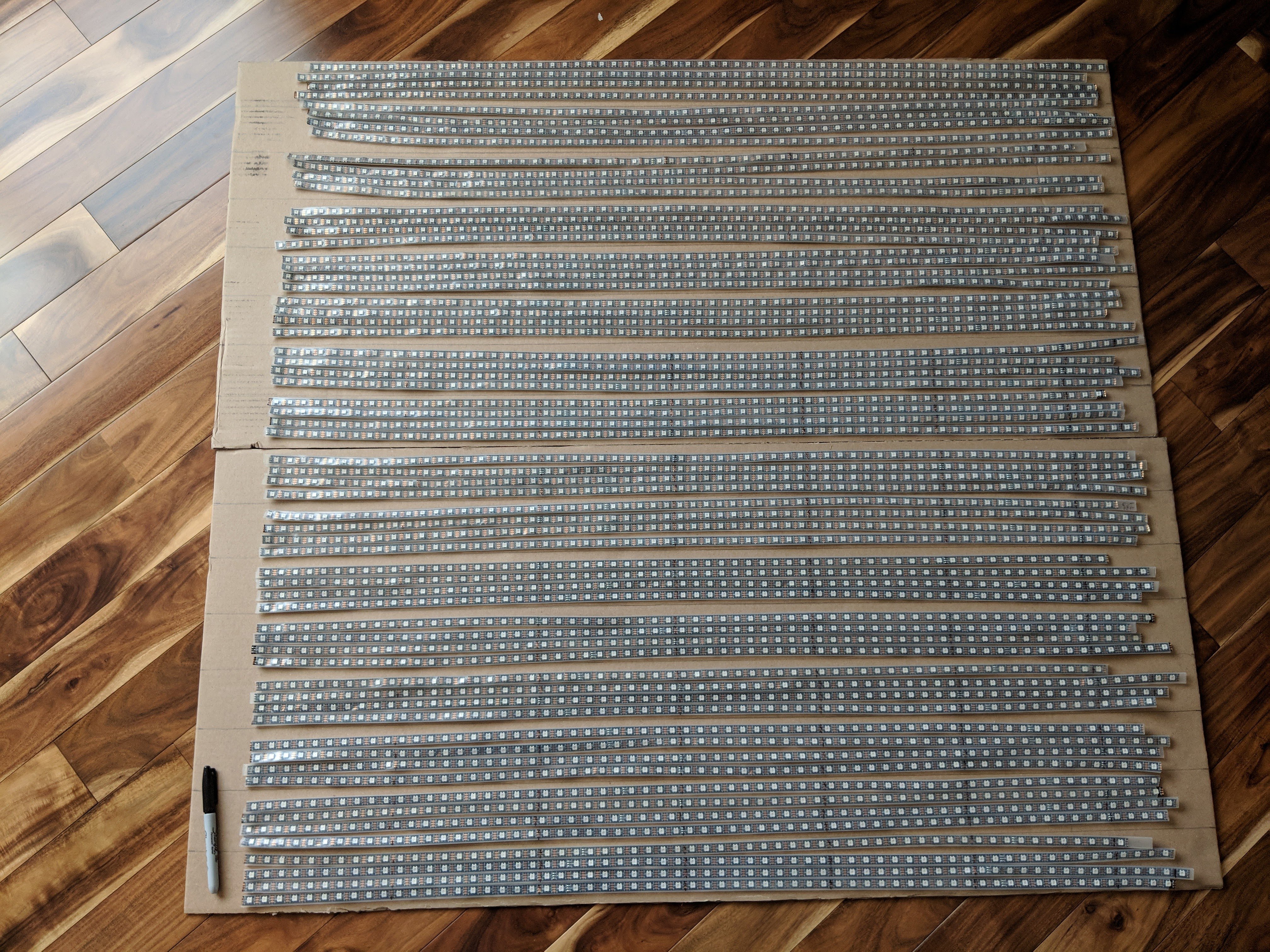
This is going to take a while (1m^2).
I inherited a bunch of strips, some cut badly, some missing a few pixels. Maybe I’ll get 64x64 working anyway, we’ll see.
What are you going to use to control it? AVR won’t cut it because of the 12kB RAM. I would personally use Adafruit’s NEOPXL8 library with FastLED’s math for their SAMD line, because then you get eight non-blocking outputs (it DMAs it out so the process of sending data doesn’t block your code). You’d have to use their M4 line, though, because it requires 12 bytes per pixel.
@Ben_Schattinger totally not going to use AVR although a mega would work, I “only” need 12KB (4K pixels x 3 bytes per pixel in FastLED). I was planning on ESP32 with @Yves_BAZIN 's branch that supports 16 way parallel output, unless by then it’s already merged in @Sam_Guyer 's ESP32 tree has the support merged in (I’m hopeful that I’ll be ready to light this all up within a week).
Now that I think about DMA, though, ESP32 only supports 8 channels for RMT (which is DMA). I guess for 16 channels, you need 8 channels of bit pushing. Is that what you did @Yves_BAZIN ?
For some reason, if it fails, I’ll switch to teensy which is supposed to support 16 way output.
I don’t need the DMA that badly anyway, the CPU doesn’t do too much but calculate the next frame which will take at least 10ms to display (256 LEDs per line)
For software, I’m planning on using the FastLED::NeoMatrix I wrote ( http://marc.merlins.org/perso/arduino/post_2018-04-23_FastLED_NeoMatrix-library.html ).
Nice - I don’t have any ESP32s, so I haven’t been following its development too much.
@Ben_Schattinger otherwise teensy has supported 16 channels for while. Not sure how slow it is given that it’s all bit pushing AFAIK, but I guess it’s fast enough 
This will be a sight to behold! It’d take some juice running at full white though

@Chris_Parton haha, it’ll be no worse than @Yves_BAZIN 's neopixel TV I just finished my first test of 256 LEDs and they used up just below 10A (as expected) on full white. That means the whole thing at full white would be 160A, but honestly I’m only going to get 2x 60A power supplies and that will be more than enough. In real life I guess I’ll be using 20-40A average maybe?
1/8th done. This is going to take a long time…missing/deleted image from Google+
@Yves_BAZIN @Sam_Guyer , I need your help with getting parallel output going.
So, I have my ESP32 outputting fine on a single line.
I guess my questions are
-
Yves, does your 16 way output use RMT for 8, and bit banging for the remaining 8, or does it bit bang for all 16?
-
I looked at your README.md, tried to get my code to do the same thing, but I get 0 output when doing this:
https://github.com/marcmerlin/FastLED_NeoMatrix/commit/f127387f008e5e2d2ca45b5e3e3f071e5cfd99e2
My addleds definition specifically, is here:
https://github.com/marcmerlin/FastLED_NeoMatrix/commit/f127387f008e5e2d2ca45b5e3e3f071e5cfd99e2#diff-591effe1e37eb4953af0ccf3765997d4R818
I plugged into pins 12 and 13 on ESP32, and got no ouput
I tried setting the MASK to 0 instead 0b1100… and no difference -
@Sam_Guyer I tried to use your fork, which works fine for a single line output (not using RMT I guess), but I have no idea how I’m supposed to define my strips for parallel output with your branch.
I checked https://github.com/samguyer/FastLED/blob/master/examples/DemoReelESP32/DemoReelESP32.ino but sadly it does not make use of parallel output.
Do you have example code I can look at and does it use the same pin order starting from 12, 13, 14… ?
Do I need non default RMT defines that I don’t have in the github diff above?
Thanks
@Marc_MERLIN morning let me grab a coffee and have a deeper look at it. From what I see you are trying to use pins 18 and 19 right ?

@Marc_MERLIN indeed 120A will be way enough just select large enough wire at the output of your power supply.
@Marc_MERLIN Hello for me it looks ok two questions
- As the Sam’s version and mine are not merged, are you using my version when #include 'fastled.h" i guess yes as you can compile.
- in the port_mask you declare pin 17 and 18 to be used are they the correct ones ?
@Yves_BAZIN thanks for your replies. I was trying to use the first 2 ports, 12 and 13 rom what I understood and tried to set the mask to ‘0’ which should enable them by default, correct?
I’ll try again to see if 17 and 18 are working instead when I define the mask where I apparently got the bits, wrong.
@Marc_MERLIN You were right in the NUM_STRIPS, just you have calculated your mask wrong.
this is how it works MASK= (1<<PIN1) | (1<<PIN2)|(1<<PIN3) …
you just added two many 000 in the masks you’ve calculated ending up pushing the signal to pin 17,and 18 instead of 12 and 13 so just replace 0b1100000000000000000(of your code by 0b11000000000000 it will owrk for pin 12 and 13
let me know how it works (the 1 are at the 13 and 14 positions as PIN 0 is at the first position) if you want to use pins 4 and 2 it will be 0b10100 other example for pin 12,5,4,2 it will be 0b1000000110100
if you are not sure just write MASK= (1<<2) | (1<<4) | (1<<5)|(1<<12)
@Yves_BAZIN ok, first the good news, I got things to work.
now, the confusion on pin mapping.
-
from your documentation it said that if the mask is 0, it should default to this “hardcoded out put for pins 12-19,0,2,3,4,5,21,22,23”
Doesn’t this mean that if the mask is 0, the first 2 pins are 12, and 13? -
similarly, given that the first 2 pins are supposed to be 12, 13, when putting a mask of 0 didn’t work, I gave a mask of 1<<15+1<<14 which is 0b11000000 00000000, not 0b00110000 00000000 which you just gave me.
With a mask of 0, I did trial and error and found that the pins used are 0 and 2 on my board (or 2, 0, I forget).
So, can you confirm the exact pin mapping order?
What is pin 1<<15, 1<<14, etc?
Thanks
@Marc_MERLIN i understand now
- this sentence was to express which pins you could use in no case the order of the pins (the one I have tested when releasing the library) the mask represent in a binary format the pin that your are using.
hence the two first bit are not representing pin 12 and 13. - picture it that way the mask is a 32 bit number representing the GPIOs (0->31) ,by putting a bit on 1 it will bet used for the output . i.e if you want to use pin 0 you will put bit number 1 to 1 if you want to use pin 27 you will put bit 28 to 1 …
this is equivalent to (1<<0) + (1>>27) . (‘1 << x’ is the operation of sifting to left by x position.
i.e 1<<3= 0b1000 and 1<<5=0x10000 …
hence to use pins 12 and 13 just write MASK= (1<<12) | (1<<13)
@Yves_BAZIN Aaaah, now I get it, thank you
So, I think it would help for you to state in your README.md, that
- pin ordering is GPIO ordering, i.e. 0 2 3 4 5 ,12 - 19, 21-23 and those are the pins you get in that order if you set MASK to 0
- that although there are 16 pins, the mask is effectively 24 bits long and that 8 bits in that mask do not go to any usable pin
Makes sense? And for now I’ll go back with a mask of 0 and use the natural order 0 2 3 4 5 etc… (since you wrote that a mask of 0 is faster)
Thanks
@Sam_Guyer how does your syntax work, is it the same pin ordering with 0 2 3 4 5 12 13 14 hardcoded? I didn’t find how you enable parallel output with your branch.