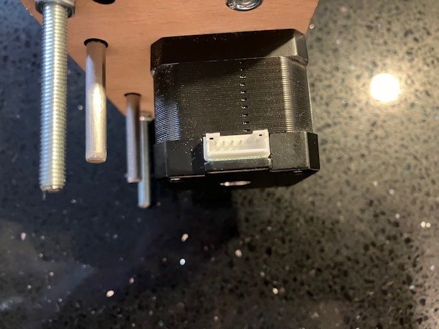
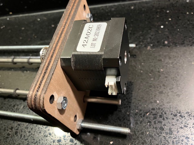
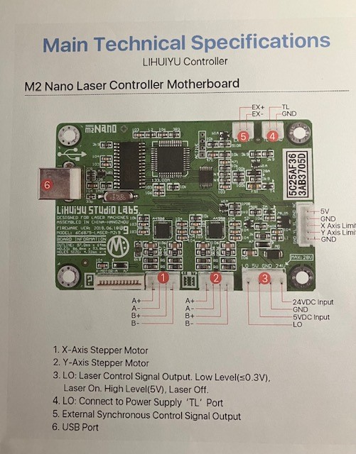
Having spent a lot of time enhancing my second-hand K40 for cutting, I returned to engraving primarily on card, glass and white tile to try to emulate the results on my previous diode laser. I have achieved good results on card and glass using a test image, so I decided to try the rotary tool that came with the laser which I have not used before now. I knew it had come without its stepper cable, but I had a spare cable from my 3D printer. I suspected I might have a problem with the wiring as I think the connections to the K40 motherboard are different from those on a 3D printer and sure enough, I believe this is the case. I have provided a photo of the Nema 17 rotary tool stepper, and I have the M2 Nano motherboard and use K40 Whisperer. When plugged into the Y axis connector, the board will simply not connect. I did look at @Don notes on steppers and elsewhere on the web, but I cannot determine with certainty the connectivity between the 6-pin stepper and the 4-pin motherboard. I know that the connections on the stepper are the two outer and the two inner connections, and I have tried a number of combinations that seemed to be correct but to no avail or might the stepper not be compatible or working? I suspect someone will be able to confirm the correct wiring connectivity as a starting point. Thanks in advance.
This confuses me. Do you mean that when the rotary is plugged in, our computer will no longer connect to the m2 nano board?
Do you have some sort of multimeter or even continuity tester?
Inside the stepper are two coils, A and B. They aren’t connected to each other.
Touch one outside pin, then probe the two inner pins to find out which one is connected. That’s one coil. The remaining two (ignoring the second pins from each end) should also separately be connected to each other.
Connect one coil as A and the other as B, it doesn’t matter which. Then if the motor turns backwards from what you want, reverse the connections for only one coil but not the other.
Make sure you never connect or disconnect a stepper motor while the board has power. Doing so can break the stepper driver chips on the board.
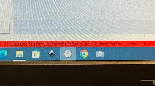
When I say it does not connect it means I get the following message. This also happens when I simply disconnect the Y axis stepper. When I plug it in again, it reconnects when re-initialised. I assume this means it registers a disconnection of the stepper. Doing the probe test, I was surprised to find that pin 1 (the outer left in the diagram) connects with pin 4 and not pin 3 as I had assumed and pin 3 connects to pin 6. This means that it was effectively disconnected as per above. Rewiring the connector accordingly it now works correctly. The only issue is with no endstop I have to press the Y endstop to reset its position, but I can resolve this. Many thanks for pointing me in the right direction.