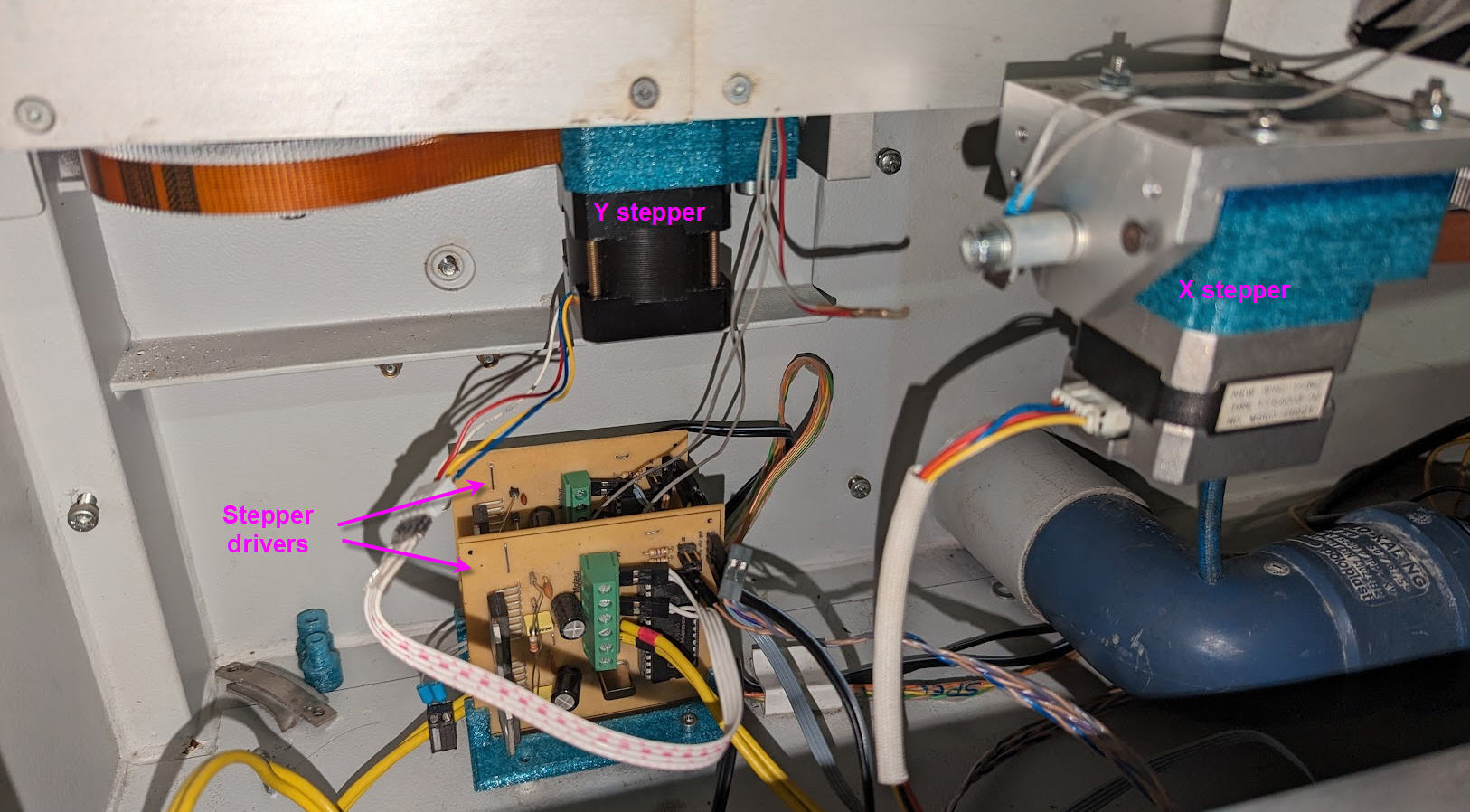
This not acceptable… I give up the idea to reuse the servo motors and will replace them by genuine steppers !
My “pseudo stepper” is definitively not suitable to control a CNC. It remains useful and precise to control a position but not a speed controlled motion…
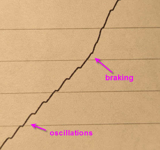
And here is the (much better) result when trying to plot a dragon head with a pen attached to the laser head.
Not a perfect drawing but the steppers behave as expected and my Trotec, even though not very fast with the little NEMA17, will be perfectly OK to cut wood !
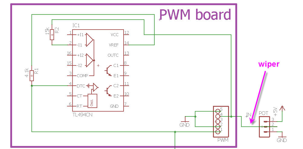
Another question is how to connect the potentiometer ? I know It is connected between ground and 5V, but where should be the wiper to produce the maximum power ? 0V or 5V ?
(It’s not obvious for me to tell it as the wiper is entering the negative input of one of the comparators of the TL494CN chip… and so ??? )
For the LPS to fire, all the enables must be asserted. But when the LV supplies are gone there is usually a fundamental failure and since the 24V and 5V are both not present it’s likely a catastrophic failure not just the 5V regulator.
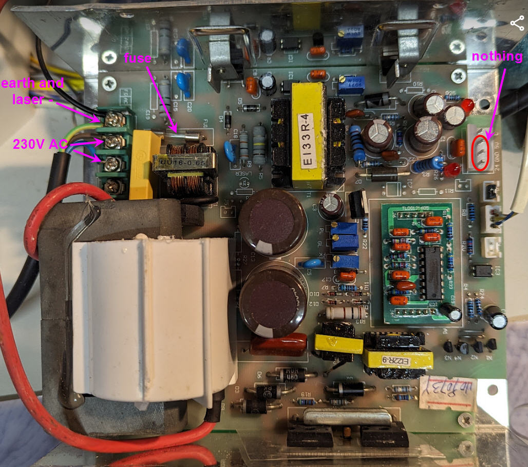
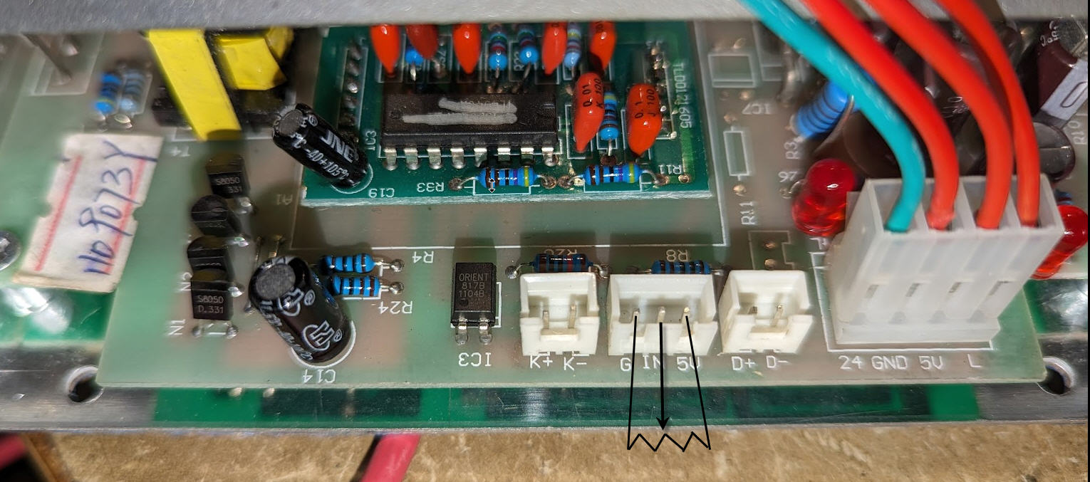
One of those RED leads should be on if there is 5V.
This was working when you started this thread right?
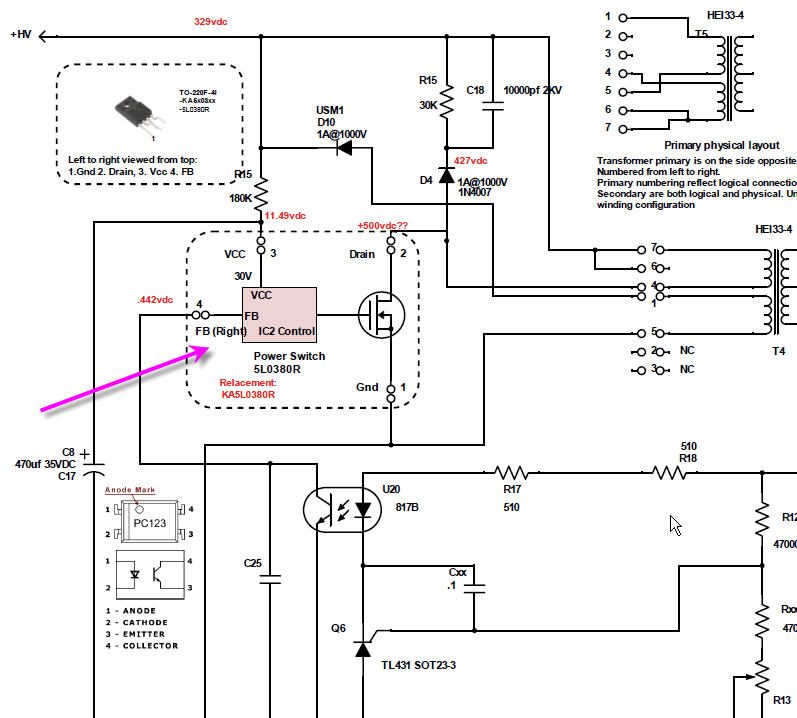
Here is a schematic for a typical K40 LPS. Most of these supplies are the same design. Yours is an older vintage based on the daughterboard for the PWM control.
I do not recommend tinkering inside these supplies for any purpose including repair. They are not really repairable.
They are dangerous exposing 20K and 600V lethal power. You have to be trained in the repair of HV equipment. HV devices are nothing like the LV power supplies we are normally used to poking around in.
They have floating HV ground meaning that you can easily blow up test equipment and get yourself connected in a way that will be painful.
It’s not economic. A new supply is <$100. My experience is that when they die it is catastrophic. A failure takes out many components so you have to replace them all at one time or else it just self-destructs again. Believe me, I have tried. These supplies are consumable anyway. The HVT will eventually fail as they are used. So even if you repair it as old as this one is it will likely fail again soon. It will easily cost you more than a new supply for the parts to repair it properly.
I usually check that there arent any external causes of operation and if not buy a new one.
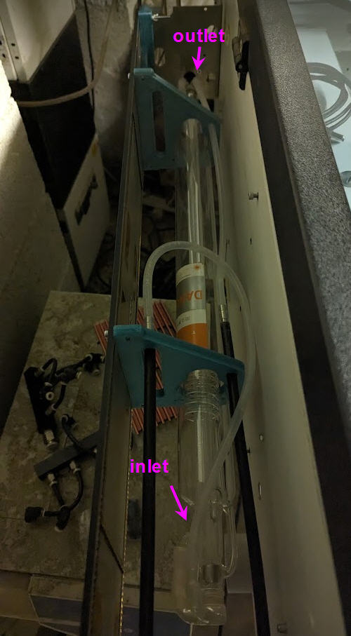
It is the very first time I power this PSU. I double verified all the connections before doing it and found no spark nor smoke when doing it !
(so never tested before)
I can’t believe it is dead… It had never been used before a friend gave it to me (with the laser tube new also !)
I will thus buy a new one… I hope it will work and also that the tube is not dead !
I am so disappointed, everything was running fine with my retrofit…
It is a bit strange that if this is a new supply, it failed this soon.
That part is switching voltage on the input side of the HV supply it has nothing to do with the input AC power.
Again I am not recommending this but this post has repair information.
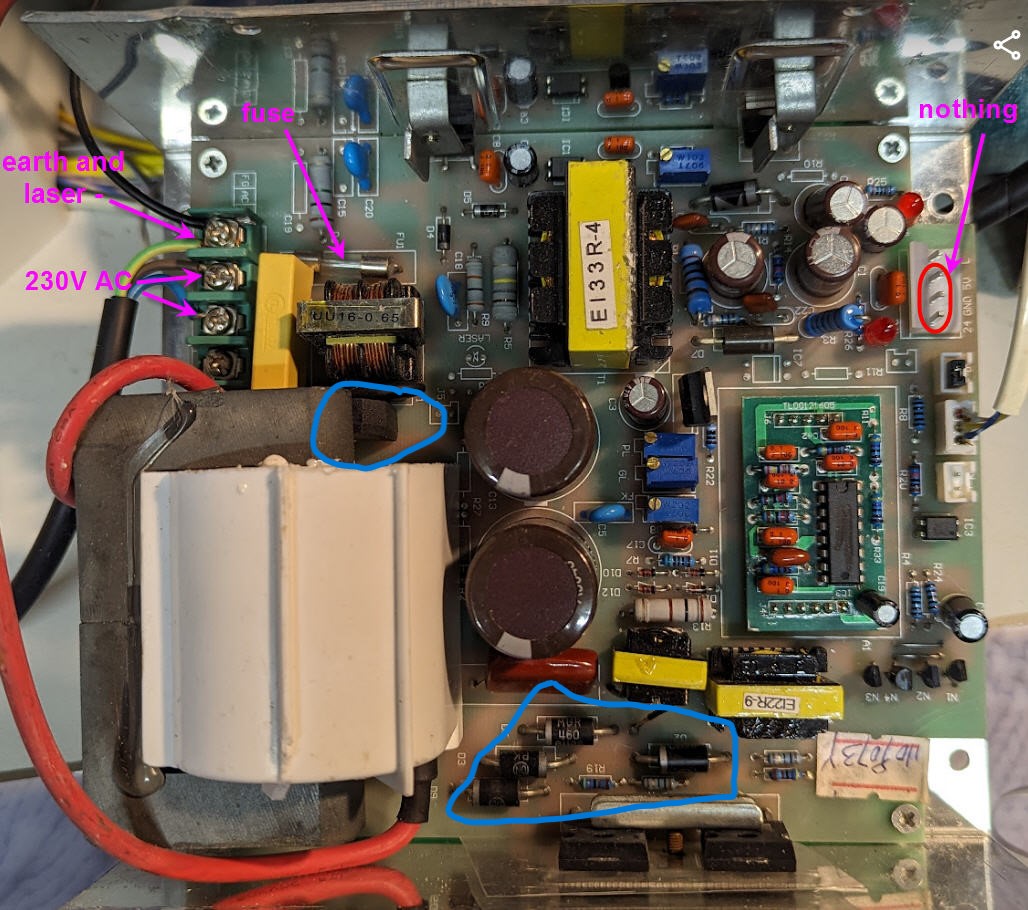
I have had the bridge and the power diodes go bad on some supplies. Blue circles in the picture. Usually, when these fail they short and blow the fuse, yours did not so I am not expecting these to be the cause.
With the input power disconnected and the output drained with a chicken stick, you can measure for a short across these parts.
Keep in mind that if for some reason you find later that the supply was good and the problem was elsewhere having a spare LPS is a good thing. That said I cannot think of any external [to the supply] reason this is not working.
Assuming that your supply’s voltage is designed to be set the same way as my schematic shows.
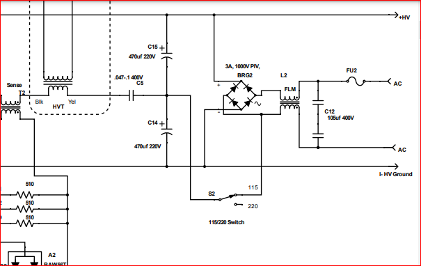
With the supply unpowered and in a safe condition, you could check to see if there is a connection where the switch normally goes.
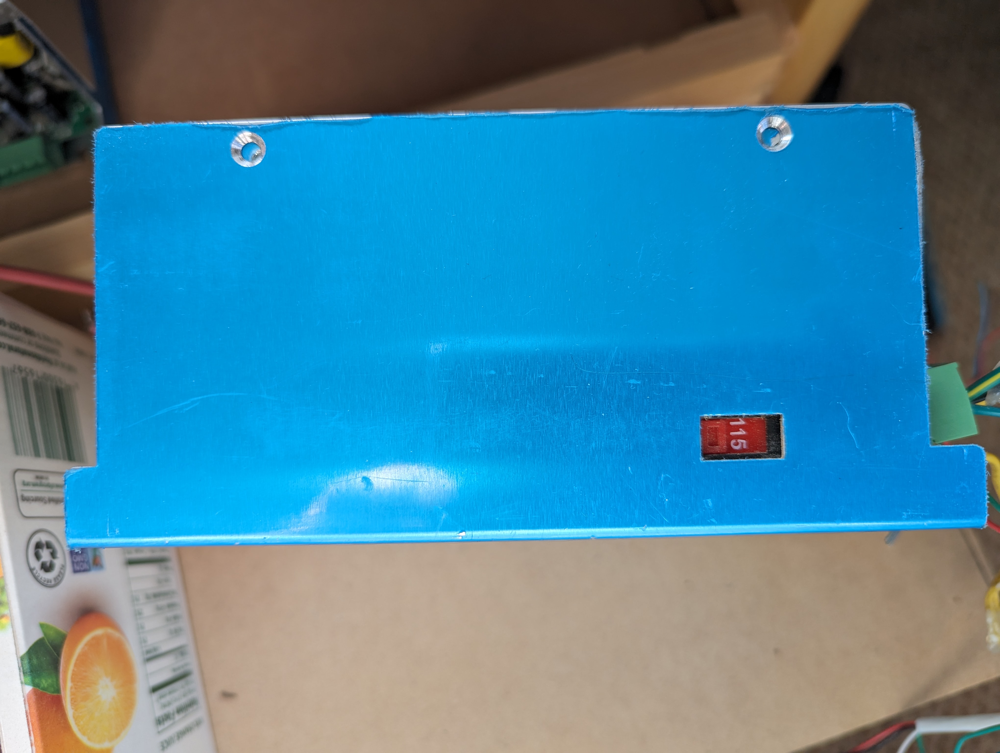
i.e. if there is a connection between the junction of c14-15 and the input of the bridge rectifier then it is set up for 115V, not 230.
Note: the component designators on the PCB probably don’t match the schematic.