Variable Voltage Power Module

Powering electronics projects are always challenging. This Variable voltage Power Module was designed to solve such a problem for a specific project that I am working on.
The ESP32 and their smaller cousin the ESP8266 are pretty well known for their high power requirements. Having used quite a few of these in various projects over the years, I wanted a power module that can supply me with enough current to keep these hungry little chips satisfied. I also needed variable voltages with more modest current capabilities, to drive LED COB modules for example.
The idea thus came to me to combine two recent projects, that I have been using together on the bench with great effect. These two are the Variable Breadboard Power Module, based on the LM317G, and the DC-DC Buck Converter that I designed a short time ago. Between these two devices, I can deliver up to 3A at 3v or 5v, or a variable voltage at up to 1.5A.
Let us take a look at what exactly was done here.
Variable Power Module
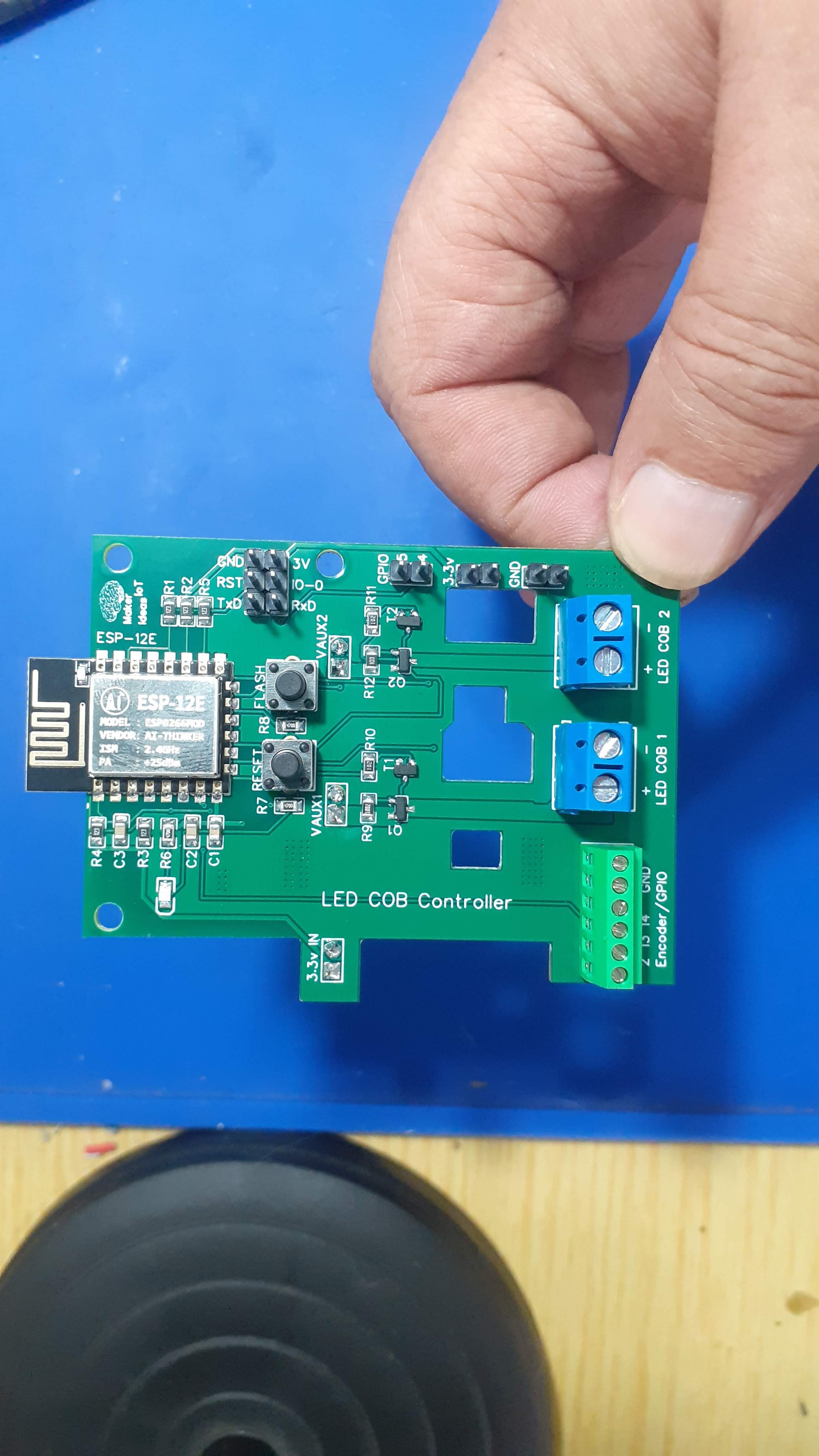
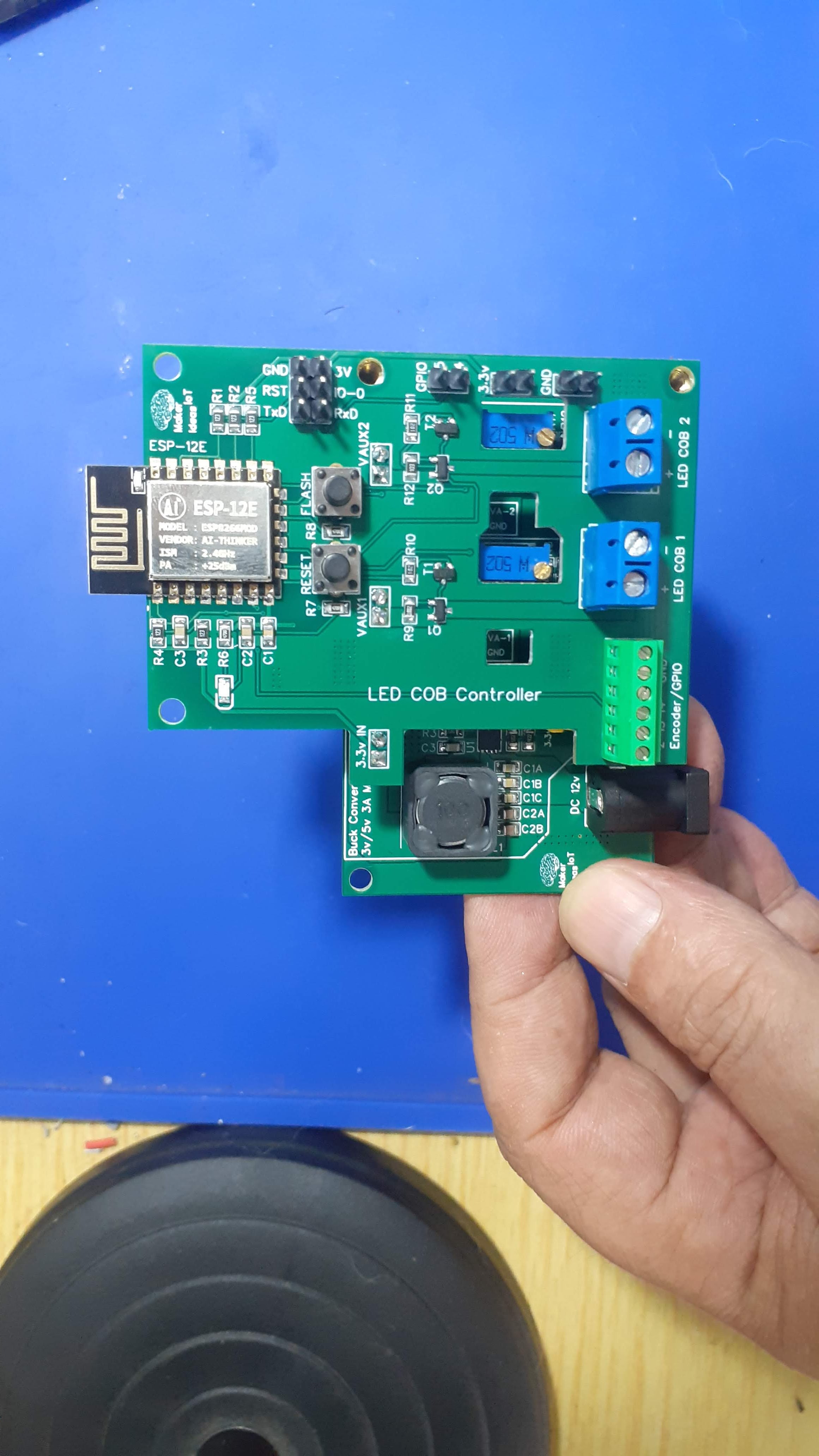
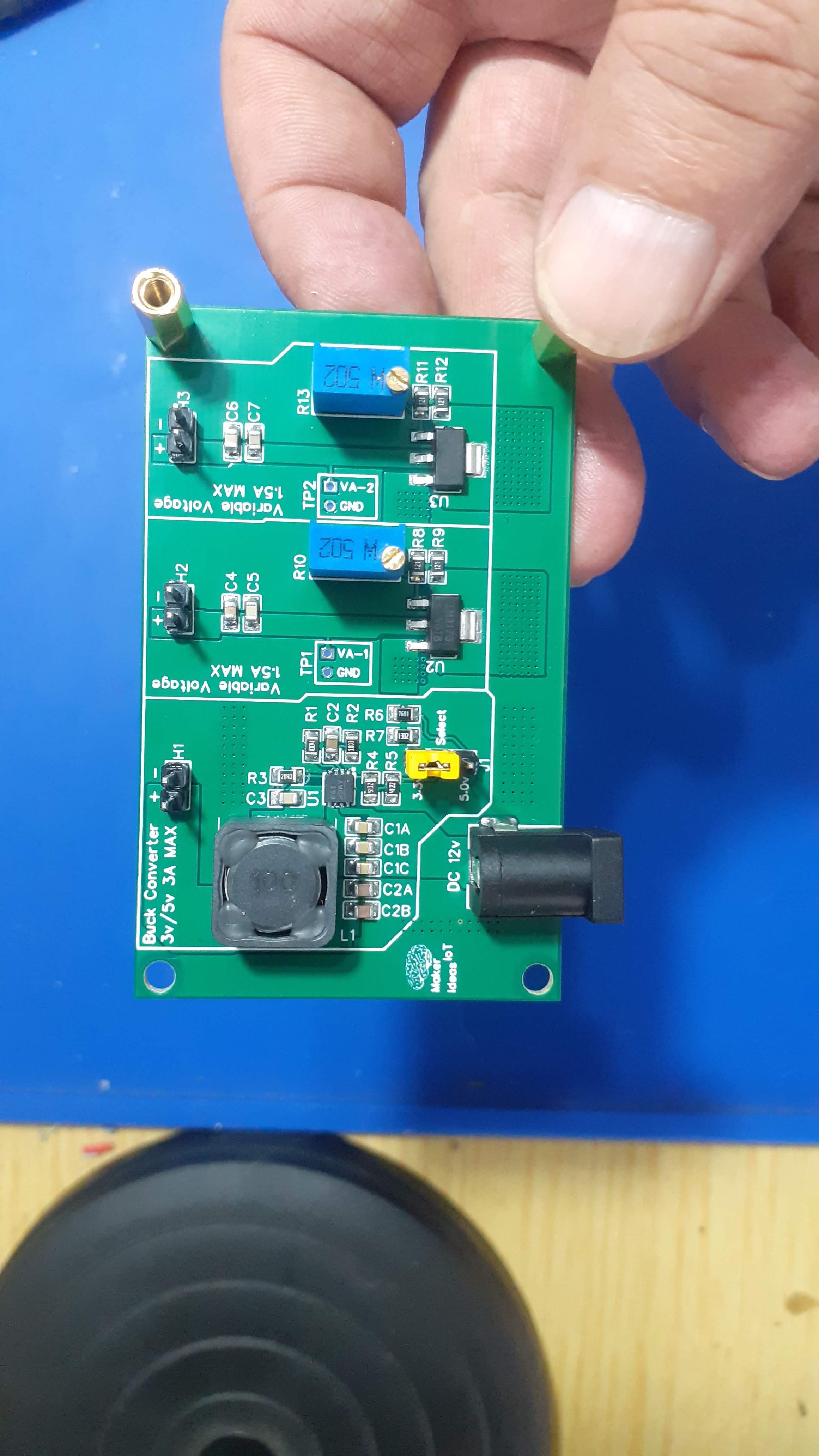
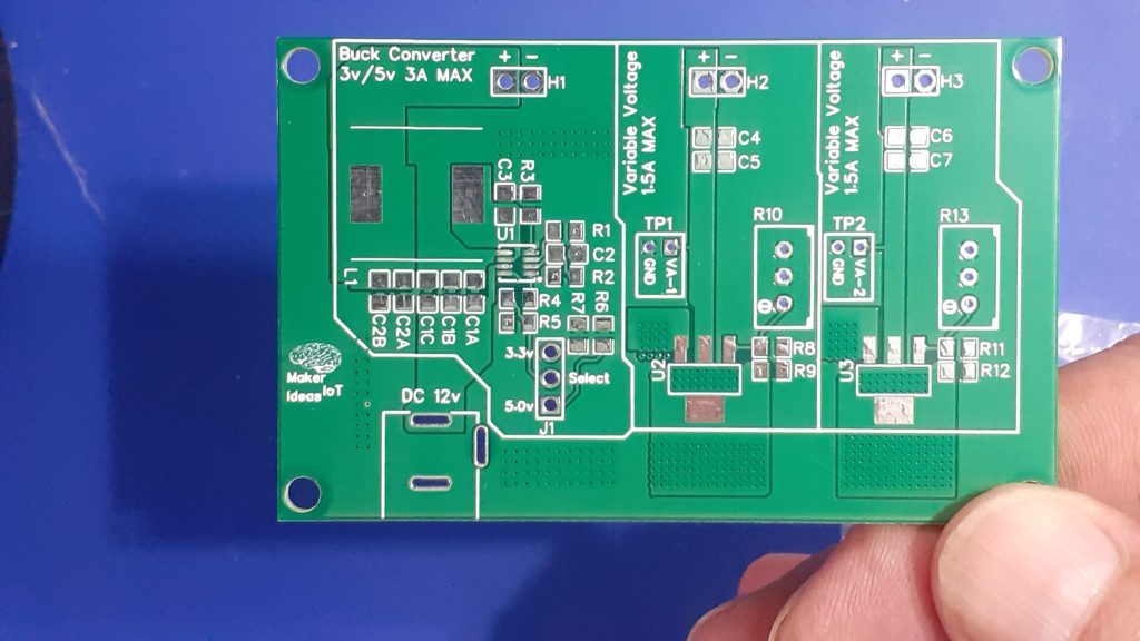
What is on the PCB?
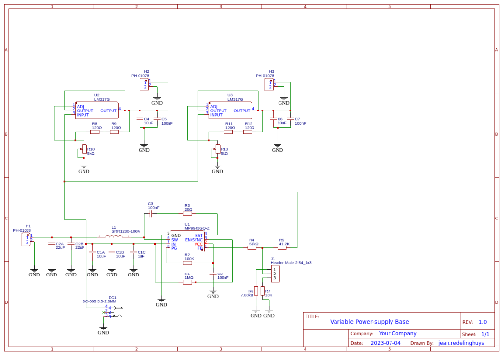
The PCB consists of 3 independent power circuits, the first of which is a DC-to-DC Buck module, based on the MP9943 from MPS. This chip can source up to 3A at a preset voltage. In my case, I chose 3.3v and 5v, as I use those the most.
The second and third parts are a mirrored section, with the humble LM317G at their hearts. These are set up as variable voltage regulators, with their outputs adjustable via R10 and R13. These two can source two independent voltages, from about 1.0v right up to about 11.5v ( if VCC is 12V) at a respectable 1.5A or current.
All of this is powered by a single 12v Power supply. Note that the 12v supply should be capable of sourcing at least 3A of its own…
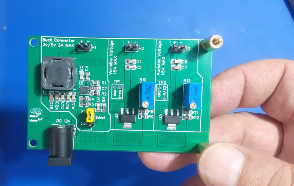
The stepped-down voltages are provided via 3 2-way headers at the top of the PCB.
How do you use the board?
Using the module is easy. Power it from 12v DC ( or up to 24v if you really want to)
The 3.3v or 5v output is selected using jumper J1 ( Please switch the power off first, BEFORE you change this). The selected voltage will be available at H1
H2 and H3 provide variable voltages, that can be set using R10 for H2 and R13 for H3. Turning the potentiometer anti-clockwise will reduce the voltage, clockwise to increase.
Test points ( TP1 and TP2) can be probed with a multimeter while adjusting the voltages.
The Schematic
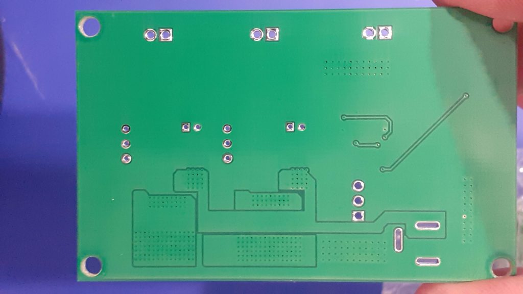
Manufacturing the PCB
The PCB for this project was sponsored by PCBWay.
Disclaimer:
Clicking on the PCBWay link will take you to the PCBWay website. It will enable you to get a $5.00 USD voucher towards your first PCB order. (Only if you sign up for a free account).
I shall also receive a 10% commission AT NO COST to you if, and only if, a paid order is generated from the click on this link.
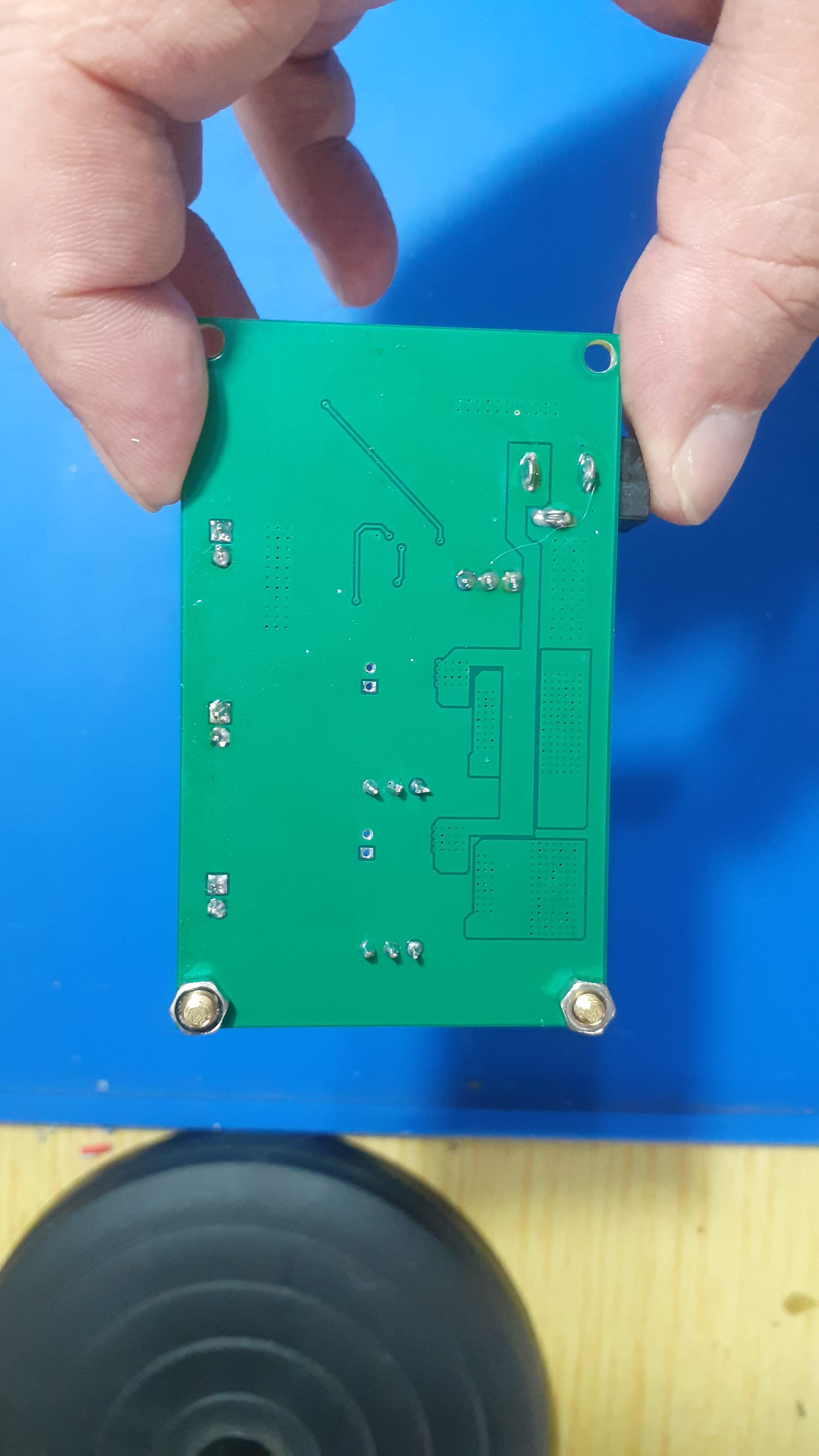
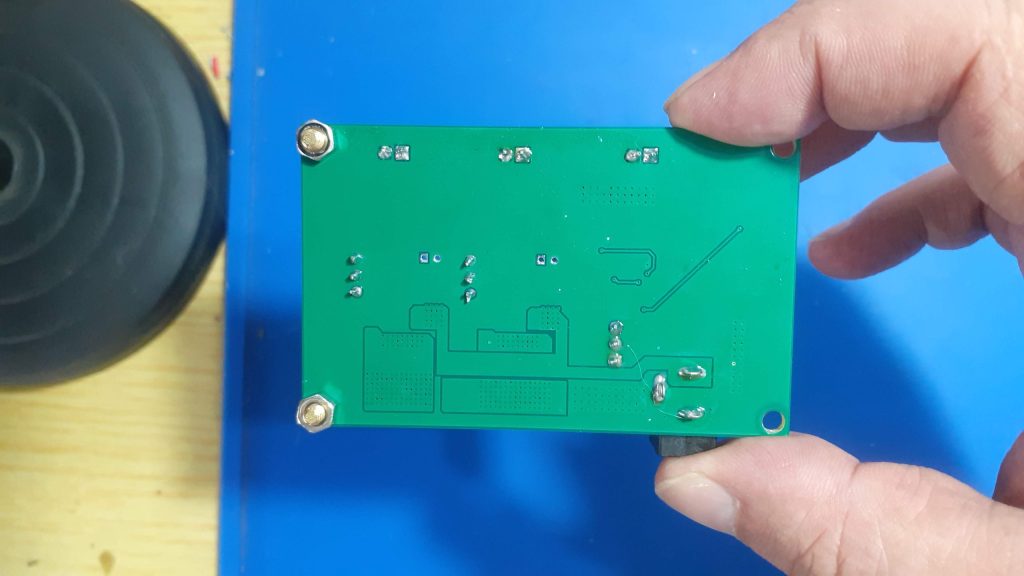
Assembly
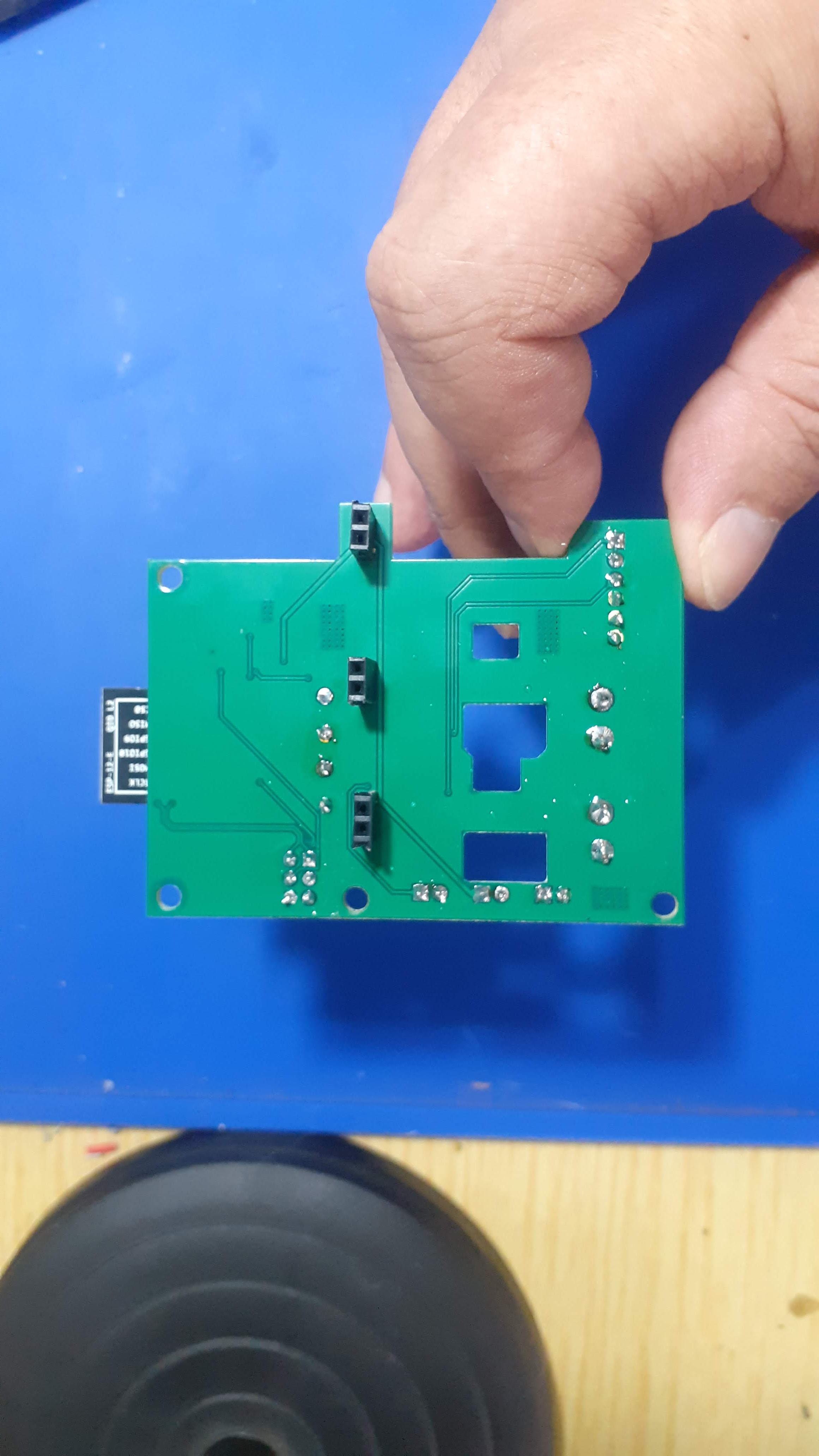
This PCB uses some very tiny components, so a stencil is highly recommended.
The Buck Converter IC is especially tiny.
Most of the other components can be soldered by hand, but I chose to do the entire assembly on a hotplate to reflow everything at the same time.
Testing
Variable Power Module
After assembly, I tested everything, measuring voltages with a multimeter, as well as adjusted H2 and H3 down to 6v, as I would be using the module on another project. I also tested the ripple on the Buck converter with an Oscilloscope, and it was well within the specs stated by the datasheet, at about +/- 100mV.
The entire module draws about 650mA at no load, and up to 3A when powering 2 6v LED COB modules and an ESP32 with I2S Audio modules connected as well.
Most of the current actually being drawn by the LM317G chips. The Buck converter is actually quite economical, drawing a modest 500mA at full load
( tested with a separate module that only contains a single buck converter module).
Conclusion
The power module works exactly as expected. It will perform well for its intended purpose, i.e powering an ESP12-E (8266) ESPHome device with two 6v LED COB modules in PWM mode, as well as an I2C display and various other sensors. In that application, I have successfully tested the entire project with a modest 12v at 1A wall-brick transformer, with no overheating or power shortage on any of the components. That is thus a win, in my books at least.