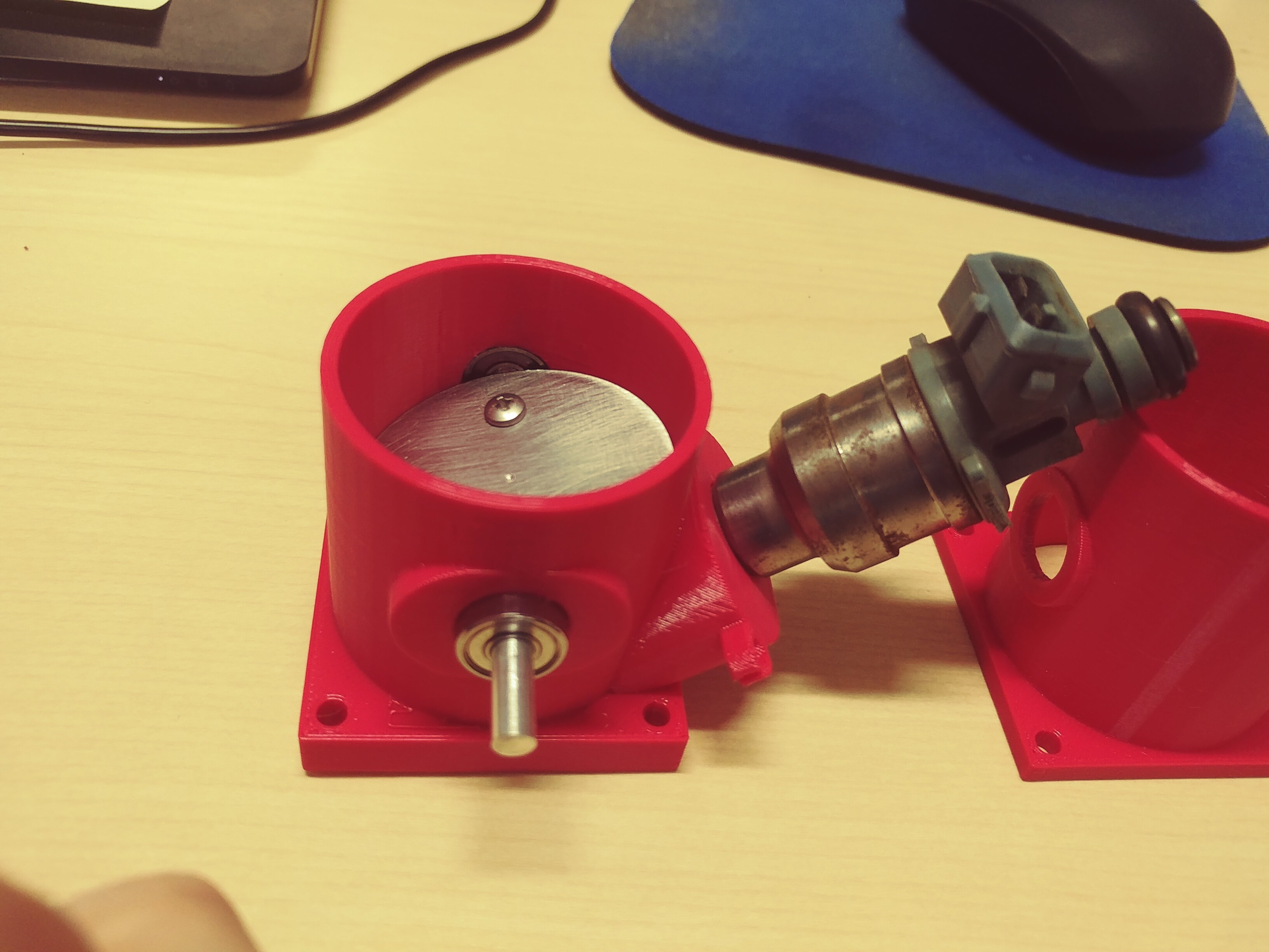
This is still a test project, not yet a real one. I’m 3d printing throttle bodies for possible casting/machining. Here’s a current version, with the throttle plate and axle and a pair of 12.7mm bearings, with the fuel injector from a mustang at the junk yard.
This has been really interesting because through using CAD I can find the angle at which the fuel injector nozzle sticks out into the airstream, the fuel injector body doesn’t hit the throttle body, and the front seal/o-ring of the fuel injector fully contacts the surrounding bore. There are any number of mounting locations that don’t fulfill some of these objectives.
This taught me to use datum planes at angles to the main xyz axes; I have two planes perpendicular to each other that define the fuel injector boss and a shape that’s the outline of the fuel injector so that when swept it defines the recess into which the fuel injector sits.
Unfortunately, I just realized I don’t have any pictures hosted in places where I can easily share links from here. Drat! I’ll have to figure out something.
Just paste the pictures here, they’ll show up inline. Any place you have already posted a picture, you can right-click “Copy Image” and then control-v to paste it here where you are editing. Or you can upload files on your computer with the upload button in the editor.
Oh cool! I missed the upload button. Will add.
Here’s a pic of one of the throttle bodies (with a previous iteration off to the right.) It has the plate and bearings installed, and the fuel injector mount at the right angle to get the injector nose in the airstream.
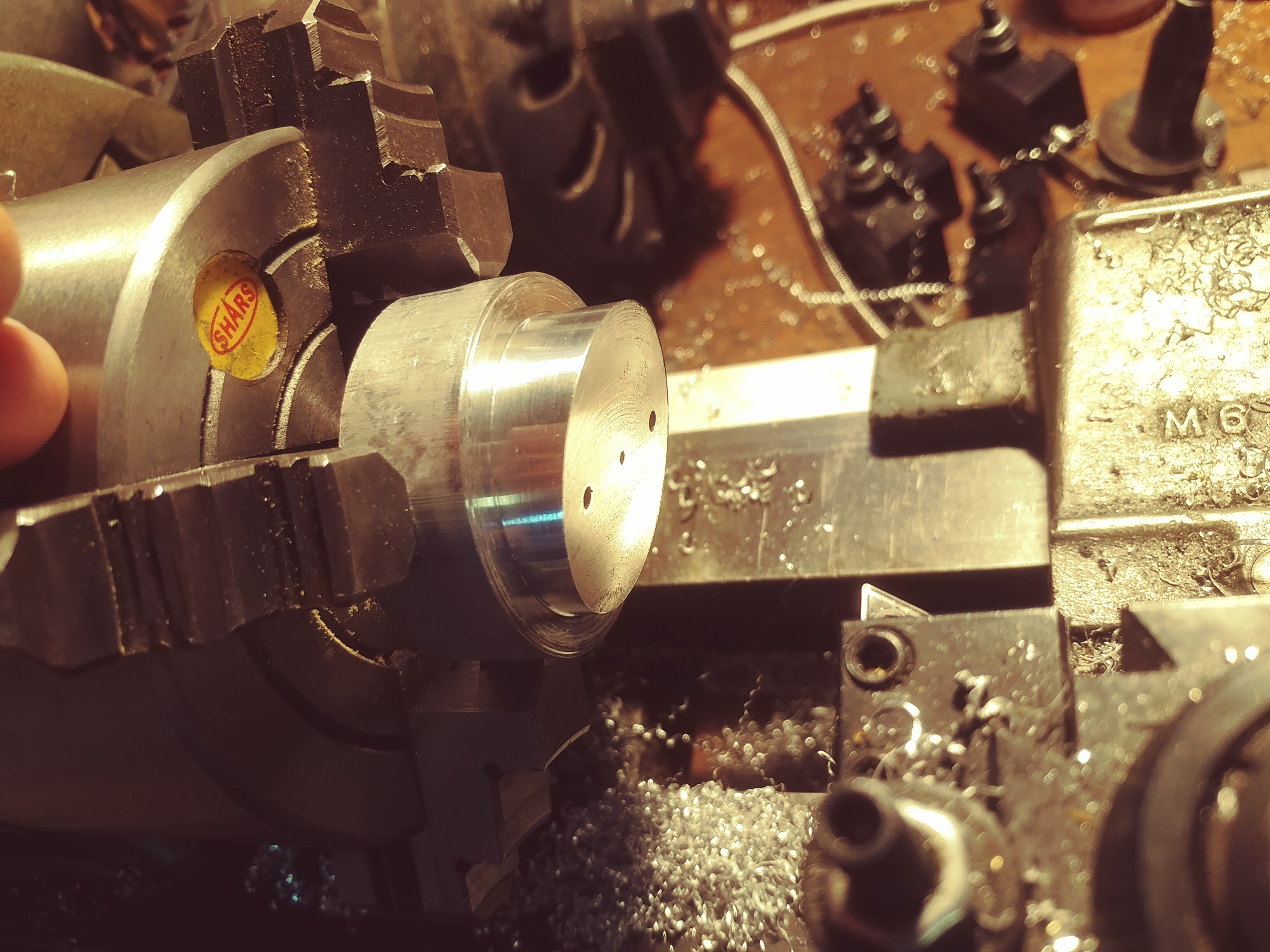
Here’s a pic of the setup for cutting the throttle plate. It needs to have the edges beveled and be cut elliptical, so when it is in the closed position it has a circular cross-section to the bore even though it’s at an angle.
As it turns out there are behavior changes depending on the angle: a throttle plate cut at about 6 degrees to the bore opens faster, so is more compatible with a high rpm race engine; a throttle plate cut at 12 degrees (which appears to be the standard) is more gradual in its opening and more compatible with a car being driven around in town.
I cut the chunk of aluminum cylindrical, then took it to the mill and mounted it using an angle vise and sine bar, flycut the top to the right angle, marked and drilled the mounting holes for the throttle plate, then recentered it on the lathe, made a cap plate to hold the metal down, and cut an oversized piece of (in this case) 0.060" thick aluminum to bolt in the middle, and lathe cut it to the right (in this case 42mm) diameter. This is in fact a little large for the engine I’m using.
I may not ever investment cast this: there are some other details that are fairly difficult to get right and this might just be a research piece in how to do this process. But it’s been fun to play with.