I have a small CNC milling machine based on a MKS DLC32 with MKS A4988 v2.0 drivers and two stepper motors (17HS8401S with 1.5A rated current) for the y-axis.
When milling longer jobs I detected more or less Y-inaccuracy and the last time I saw that one of the y-stepper motors stopped working for seconds. After aborting the job immediately and moving the X- and Y-axis with normal positioning commands, both y-steppers work fine again.
I thing cabling is not an issue and the gcode program does not address the two different y-steppers.
After a lot of digging into the grbl controller HW stuff, I read about the stepper drivers and the current settings and about lost stepping in case of invalid current settings.
I guess the two Y-steppers are connect (serial or parallel?) to one of the three A4899 drivers.
I measured the ref voltage of the A4988 drivers and all three have a setting of about 0.95V.
Is this value ok for the two connected Y-axis stepper motors?
Is there another reason, why one of the Y-axis steppers stops working?
So one driver is driving 2 stepper motors? I would think a better way to do it would be to have 2 drivers and have the Step/Direction lines driving each of the 2 drivers.
I have had wires to a stepper motor which had been damaged at the crimp. They “tested” fine but when running were intermittent.
I believe they are connected in parallel. This is sadly the worse combination; series connection is preferable, but few control boards with dual Y outputs do. You can generally tell the ones with serially-connected Y motors because they come with jumpers for when only one Y motor is connected.
Long ago, before I converted a printer with dual Z axis from two motors to one motor and a belt, I made a converter to run two motors in series instead of in parallel.
But if they are wired in parallel, the current will be shared between the motors; each motor will “see” the full voltage but only half the current.
If they were wired in series, the full current would go through both, and each would see half the voltage. (This generally works fine with 24V supply; might not work as well with 12V supply.)
If they were in series, if the wires broke to one motor, both motors would stop turning.
Without changing anything else, and assuming your Vref is correct for one stepper motor, and assuming you are right that there is no problem with the physical wires, you might expect to want to increase Vref from 0.95V to 1.9V. However, the A4988 has a max current of 2A and if you have a 0.1R sense resistor, 1.9V would be too high. It might simply be that your stepper drivers are not sufficient for your steppers.
To be honest the description of this really shouts ‘intermittent connection’ to me. You can get bad contacts in crimped connectors, as @mcdanlj says, and also internal failures in the wire.
This is often caused by the wire being crushed or strained in the past. Leaving a hidden half-contacting break somewhere in the cable that only shows up occasionally, usually as the wire is disturbed or heats up…
I’d start a long, slow Y axis move and then ‘wiggle’ all the connectors and cabling for the affected motor to see if that can narrow down the problem.
Also, If you can see the back of the controller card, have a good look at the soldering on the socket. Make sure it is not incomplete, cracked or dry. This is another common place to get these sorts of issues.
You could also swap the Y motors to see if the problem is a bad motor.
swap the Y motors is a good idea.
I tried to reproduce the problem, but this cannot be done safe without the risk to damage the machine. I do not want to run the machine a long time without human attention, because the problem will give high force to the mechanic.
I checked the voltage which is 24V, so the two Y-motor in series should not be a problem.
At the moment I slightly increased the ref voltage of the Y-stepper drivers and checked the temperature while a running milling job. Temperature was very low, so I guess that this change will not cause a problem.
I will try to check all your suggestions step by step and I will provide the results here.
As stated in my first post I am not sure and I do not know much about stepping motors and the connection to the drivers.
On this page, it is explained how and why a serial connection of two stepper motors makes sense:
Wired in parallel the stepper driver needs to provide double the current. Step sticks have limited current ability. The stepper motors can be fully driven from 12V. On a 24V system, there is sufficient voltage available to put the rated current through two motors. In addition, the series wiring will always put the same current through both motors. Any racking force turns into back-EMF which will cause a change in impedance between the motors if they are wired in parallel.
Before the wide, cheap availability of boards with lots of extra stepper drivers on them, wiring two motors from a single driver in series instead of parallel was a common 3D printer upgrade, predicated on upgrading from 12V to 24V. And some control boards that have a stepper with two outputs have then wired in series. You can tell these boards because if you are driving only a single motor, you have to put jumpers on the output.
I haven’t read that particular page to know whether that particular author’s logic is good, but the practice is well understood and commonly used, and the associated graphic looks right to me.
Seems odd he’d wire them in series with a 12V source… he also stated dc characteristics ignoring the impedance issue.
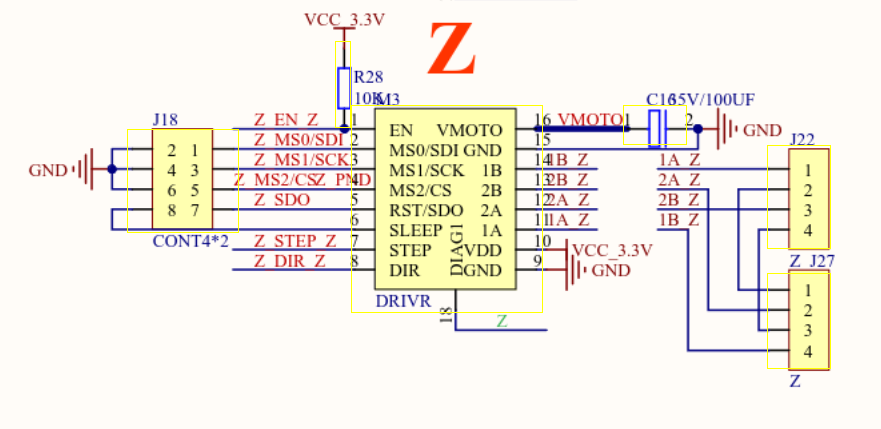
It’d be nice to have a schematic of some of these…
How is this supposed to be handled with a DCS32? … the driver outputs from the chip only has the xyz axes going out. Didn’t see any differentiation between axes/motors…
Maybe it doesn’t support dual motors out of the box…?
Whether it also works with 12V depends of course on the motor’s impedance. A pair of motors rated at 3V would be fine. But you have more head room with 24V.
By using one stepper driver with two motors. Best done in series if you can, as discussed here. What’s the confusion?
If these boards, like DLC32 are pre-wired for any type of connection besides parallel…?
I’ve got one of them sitting on my desk, in my mind, I’d like to stick it in my china blue and see how well different configurations work. I also have a ssl that has two motors, with it’s original no-name controller. I’d cough up the bucks for another DLC to upgrade it…
In the end, I guess, I’m pumping you for information… sorry
This particular board, like most boards, isn’t pre-wired for series stepper wiring. Some such boards have one axis pre-wired for parallel stepper wiring with two header connectors. Others don’t have any explicit affordance for multiple motors driven by a single stepper controller. Either way, on such boards, series wiring has to be done off-board. (This is what I did long ago, by making an adapter.)
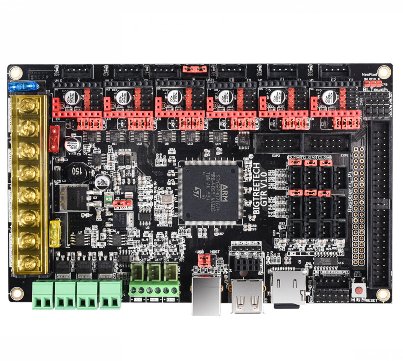
Some boards are configured pre-wired for series stepper wiring on one axis. Boards that are pre-wired for it require jumpers when the series feature is not in use. For example, the BTT GTR has an axis like this. I’m not using that feature on the printer on which I’m using that board, so I have the jumpers installed. See the two red jumpers on the top middle of this image:
My point is that regardless of whether a board is explicitly provisioned for driving steppers in series, it is possible, and at least at 24V arguably desirable, to do so in preference to wiring steppers in parallel, in order to be able to reach desired current on both motors.
(Sorry, this is a little off-topic for the MKS DLC32; just trying to clear up this point… )
Also OffTopic but I wanted to point out that it’s not just the Resistance of the motors that is affected, their Inductance follows the same rules, doubling or halving for series or parallel wiring the same way.
This can affect and limit torque and response speeds, the drivers ‘chop’ the output signal on and off at high frequency to provide current-limited power to the motor. Changing the load inductance affects this, and the driver characteristics change (at worst; you risk damaging the drivers by if the inductance they expect to see is too low.)
Not much of an issue with the commodity motors, drivers and setups discussed above, but it is the sort of thing that becomes relevant in more complex scenarios.
Good resource from LinuxCNC.org here: Stepper Information