Ok Jerry, we got this.
I understand what you are thinking by the way that’s hooked up. It’s logical to think that the shifter goes “inline” with the data flow, and that’s true, but there’s more to it than that. You also have to power each side of the internal chip, each half gets it’s appropiate voltage.
We have signal wires of 3.3 and 5v and we have power wires also at 3.3 and 5V
You need more wires. I’m going to give you a wire by wire list of how to connect this
Wire#1
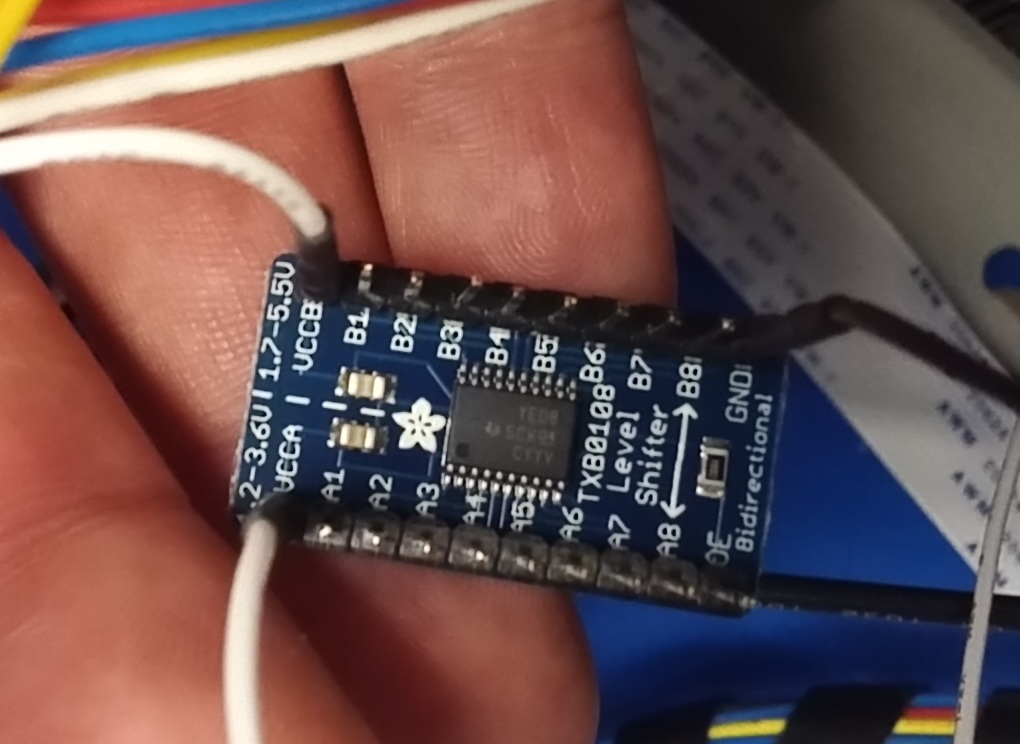
1st, take the wire on VccA and move it to A1 (this connects the 3.3v SIGNAL output of the SB to the input of the level shifter)
Wire#2
Then take the wire from VccB and move it to B1 (this connects the output of the level shifter to the laser fire input 5V SIGNAL) Confirm that this wire is connected to pin 4 (L) on the PSU
Wire #3
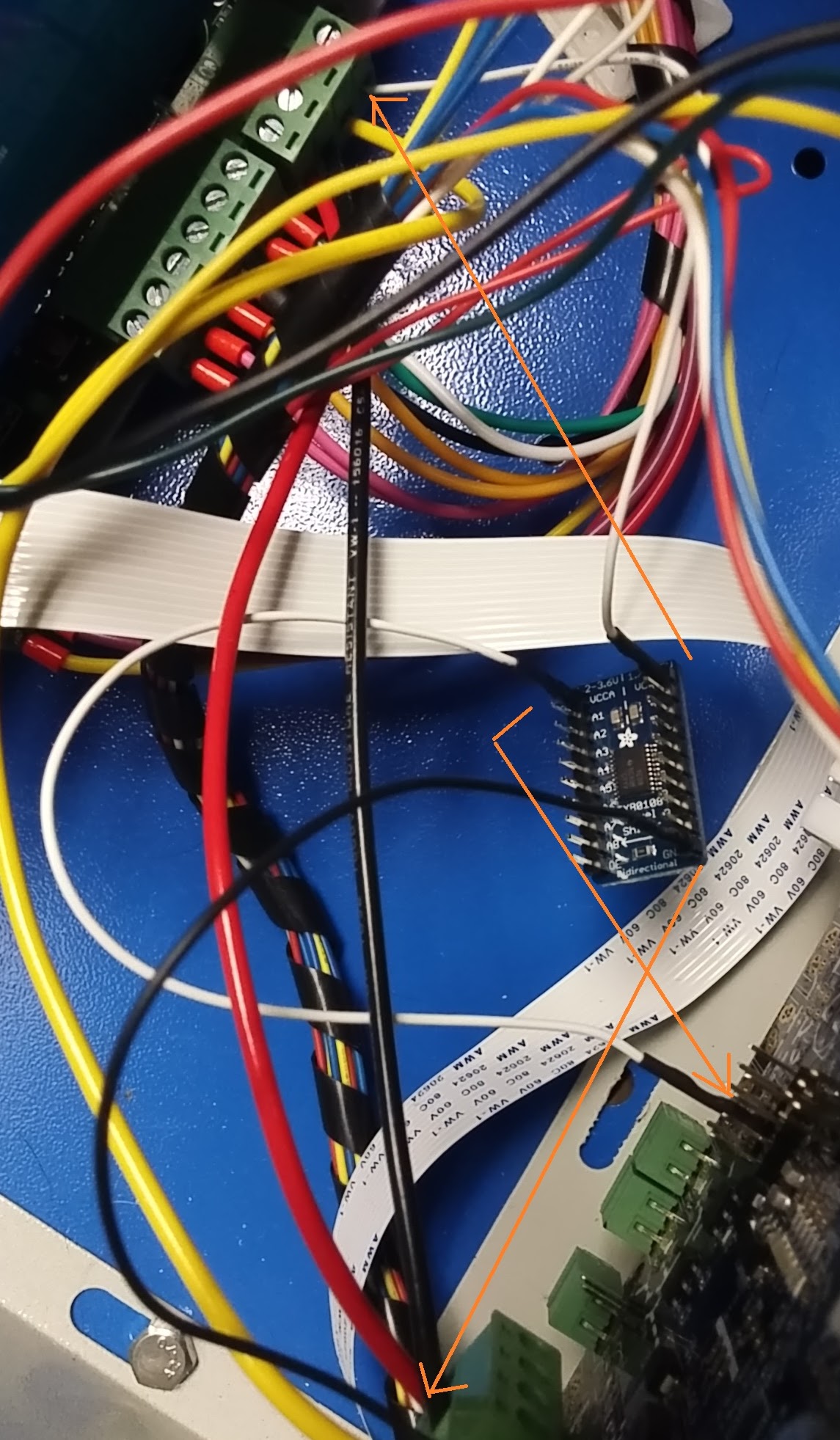
Now we need to add power to VccA. It needs to be 3.3v. I usually like to use an external supply here, but you CAN use internal SB 3.3v regulator and “steal” some power. Look at the center Smoothie. next to the processor there are a group of 6 pins. looking at the board with the USB connector on the right, the pin on the right corner will be marked 3v3. Use a magnifier to verify if needed. Connect this pin to VccA with a wire.
Wire #4
Now for the 5V power - it looks like the best place to get this is right on the Smoothie +5v connector. This should already be connected to Pin 3 of the PSU. (The photo is dark but it looks like you have the heavy yellow wire connected to the wrong pin, make sure it’s connected to PSU pin 3) That heavy yellow wire that connects PSU pin 3 goes to the Smoothie right most power connector (looking from the power input end)This is pin 4.
Once you’re sure that’s right, put your new wire into the Smoothie Power terminal #4 next to the heavy yellow one, the other end of this wire goes to VccB
Wire #5
One last thing. You need to connect pins A2,A3,A4,A5,A6,A7,A8 to the ground. If you don’t do this the shifter chip can oscillate (like feedback) and damage itself - at very least this can cause it to not work. so, use whatever technique you need to but ground those unused input pins.
Wire #6 - this is your existing ground wire and it looks to be connected correctly. it should go from the Gnd on the level shifter to pin 2 on the PSU (or to the 5v ground on the Smoothieboard)
Make sure your Smoothie power is connected correctly If you look at the power connector with the USB connector on top, on the left is the VBB (motor) power, and on the right is the +5v power.
Pin 1 is +24 power in and should go to pin 1 of the PSU,
Pin 2 is the 24vGround and should go to pin 2 of the PSU.-
-Pin 3 is the 5vGround) (it’s tied ti the +24v ground) and it also should be connected to PSU pin 2.
Pin 4 is the +5v Power in and should go to pin 3 of the PSU
Remember the Grounds (negative) are the center 2 connections. 24v is VBB and the +5v is covered up by the QC sticker, but is the right side and IGNORE THE SILKSCREEN + & - markings)
Be careful here, the silkscreening on the Smoothieboard is wrong, and an error here will destroy the Smoothieboard.
This should do it.