Ok, my board was an M2Nano.

On your K40 PSU, pin 2 is Ground and pin 4 is Fire (active low).

Connect the Ground pin (pin 2) to the Smoothieboard Ground (there’s a whole row of ground pins next to the 2.4 Pins row, and one at the end of the 2.4 strip).

Connect the PSU “L” or “LO” pin to the input (3v3) of your level shifter.

Connect the output (5V) of the level shifter to Smoothieboard pin 2.4.

You will have to solder in sections of header strip to make the connections, then use a Dupont style pin connector to connect. Both pins and connectors are included with the Smoothieboard.

Good Luck, Scott

@Scott_Marshall I’ve got pin 2 going to the power header with the 24v. Do I need two wires going to that ground pin?

If you’re using that power supply for other things, they will need to be grounded as well. If you’re already grounding the 24v input of the Smoothieboard with that wire, then the Smoothieboard is already grounded to the K40, and you won’t need to worry about an additional ground.

All you need is one ground wire between the K40 PSU and the Smoothieboard. Make it a fairly heavy one and keep it short as possible for good signal transmission. Twist the wires between the K40 PSU and the Smoothieboard to minimize noise issues. 18awg is what I use in my kits.

Ok, wired up 2.4 to the B Side (5v) and the A side (3.3) of the leveler to the L pin on the PSU. Fired it up and …nothing. Laser did not fire.

Ill check the voltage coming off each pin tomorrow. :confused:

Check your Config file and make sure the laser module is enabled, pin 2.4 is selected and inverter ie 2.4!

Then check the voltage on pin 2.4. It should idle at 3.3volts then fall to 0 when the laser is being called on. Then make sure the output is doing the same, but holding 5V at idle.

Ok. I used your config file and it looks like its enabled. Ill check the voltage tomorrow.

@Scott_Marshall Now im not sure what’s going on. I can ground the leveler and trigger the laser

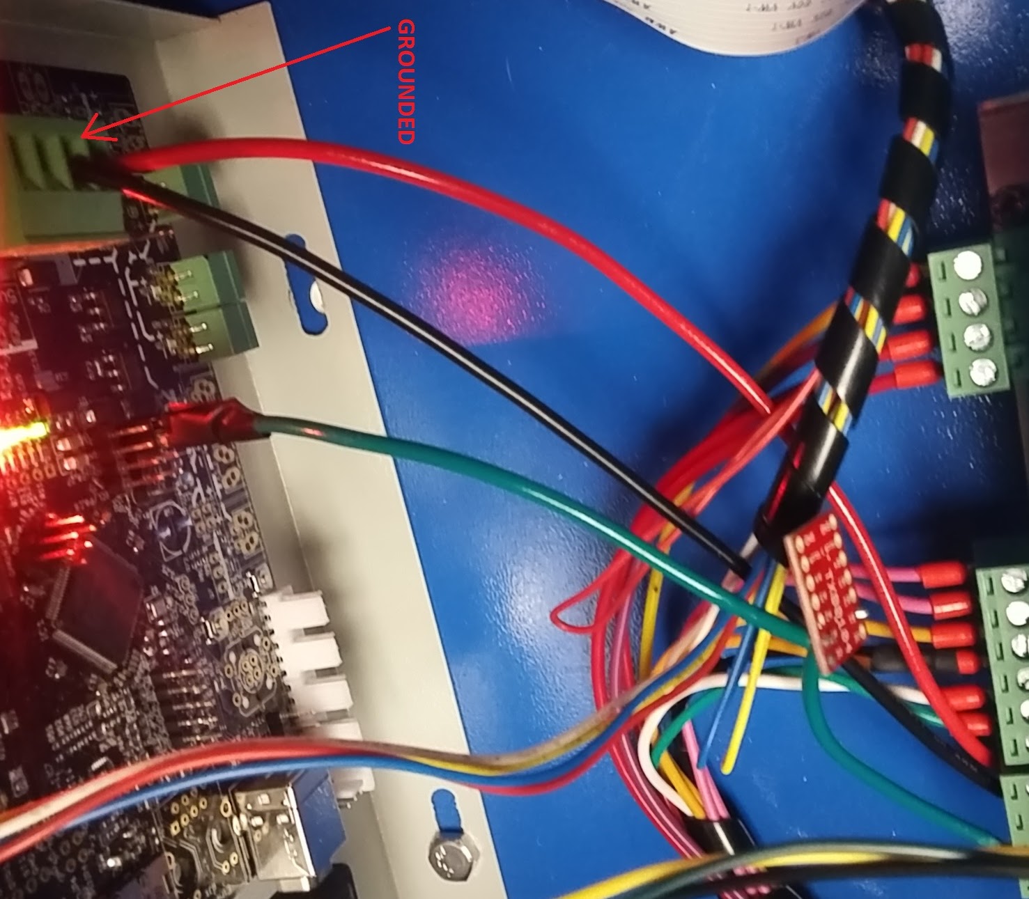
I see you connected the Smoothie to the 5V side and the Laser to the 3.3v side, that’s backwards.(somehow I missed that in our last interaction) The K40PSU uses 5V negative logic and the Smoothieboard uses 3.3v logic (thus the need for a level shifter).

No harm should have been done to the Smoothie as long as you had it connected to the INPUT on the 5V side.

Connect the level shifter so that Smoothie pin 2.4 connects to the 3.3v INPUT and the 5V Output is connected to the PSU ‘L’ Pin. and try again.
You’ll have to change the setup of the level shifter to use 3.3v as the INPUT and use the output as the 5V OUTPUT

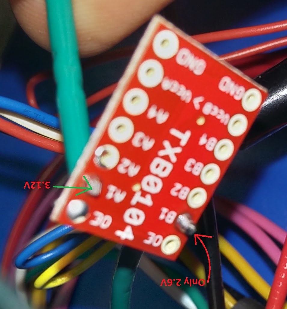
There is another gentleman who is also having problems with a Sparkfun level shifter.

I’m not real familiar with the Sparkfun device, but the setup for any “raw” level shifter can be a little confusing for someone without much logic circuit experience. On MOST of them you have a direction line which designates which side (A or B) is In and so on. Some require one side be the higher voltage, where with others it doesn’t matter as long as the Vcc is powered from the correct voltage power supply. You really have to pay attention to the details. To top it off, each manufacturer has their own way of writing the spec sheet, making it hard to compare ‘apples to apples’. To further complicate things, all the new slick ICs are only available in super micro SMD packages. You would think they would release them in Good ole DIPs for testing and prototyping, if not for the forgotten hobbyists for the engineers to use in prototyping and testing. SOT and SOIC packages are now considered huge and wasteful. A far cry from the old “stone sandwich” days.

==================================================
The ALL-Tek Micro-Mark Level Shifter
Since we see so many people here with level shifter wiring questions, I decided a solution would be worth creating. Actually I already have a solution available in my ACR series, but for people preferring to ‘DIY’ it, I’ve created The ALL-Tek “Micro Mark” Level Shifter. It’s a plug in solution to the level shifter issue, and addresses several common level shifter problems such as loss of power.

It uses very low ON resistance MOSFETs for the output so you get 100% of your Lasers power when you call for it. Many logic shifters don’t pull the input all the way down to Zero Volts because .9v is the standard permissible logic “0” signal and my device is purpose built to fire a K40 so it pulls down to within a few microvolts of true Zero.

It also includes full optical isolation, with only a beam of light between your Smoothie and K40. Not even the ground is shared so it eliminates any concerns about noise transmission, ground loops or power supply interactions.(thinking of you Julia)

It uses positive logic, making it safer than traditional level shifters, and requires a positive 3.3v signal to fire. This prevents inadvertent firing while the Smoothieboard boots up. This change does require one small change to the Config file(you just delete the !), but it comes with ALL-Teks EZ-Config for the K40 on DVD along with full instructions.

It’s self powered, drawing it’s very small power requirements from the drive and driven devices, and last but not least, is solder free and comes with cables that plug into the Smoothieboard and K40PSU. Fully PWM compatible with plenty of bandwidth.There’s a input and output LED to make any unlikely troubleshooting easy. It’s 1 1/4" square with 4 M3(6-32) mounting holes on 1" centers. $29.95

The 1st batch will be available soon (boards are being made now)

Scott

@Scott_Marshall the smoothie is on the a side (max 3.3) and the PSU is on b (max 5.5). Also I had it reversed before and had the same problem

You need to start checking voltages then:

Check the Smoothie side:
Unhook the shifter and put a meter on the 2.4 pin. Verify it’s steady at 3.3v idling and dropping to Zero while firing. NOw you know if the Smoothieboard is OK and the software set up properly.

Then check the Shifter side:
If that works, try grounding the input of the shifter and make sure the output is going to Zero. Then Jump the shifter input to 3.3v and make sure the output is 5v. If all those are satisfied, when you connect it all up, it should be working.

Make sure the pin 2.4 is still swinging 3.3v to 0v after reconnecting. Some level shifters demand a fair amount of current, and the Smoothie output pin is directly off the processor, so can only supply a few ma (which is what makes it so easy to damage if mis connected)

Scott

@Scott_Marshall pin 2.4 only gives 3.12V. I didn’t think it was a big deal because when I ground side A of the shifter (while connected to 2.4) the laser fires.

The B side is 0 V when not plugged in to L, but 2.x when connected to L.

If Side A is your input, and the laser fires when you ground it, then your level shifter is working.

The 3.12V thing isn’t great, but usually acceptable and probably your meter. Try checking one of the 3v3 pins (there’s one in the cluster of pins next to the processor, on the corner) and see what it reads. The regulator used in the smoothie isn’t prone to inaccuracy and if the voltage is down that far, you may have a load on the supply somewhere pulling it down, or a very weak 5v supply - this is common if powering from your USB port, a lot of computers just can’t supply the 330ma the Smoothie draws just idling.

You didn’t mention if the 3.12v drops to zero when you call for the laser to fire. That’s the important end of things on that output.

Hook up your meter (find out what’s up with low voltage 1st) and run a small .svg cutting job on Laserweb3. It should drop to Zero when the cut begins.

That’s pretty much what we’re down to. It seems all is well with your Level shifter/psu., it’s just not getting the 0v fire signal from the Smoothie.

@Scott_Marshall it does, indeed drop to 0 while running an svg. At no point does the 5v side drop below 2v though. :S

I hate to hijack your conversation, but I wanted to ask Scott about the pin dropping to 0 when firing. Should it be dropping to 0 regardless of the laser power percentage?

@Scott_Marshall wow, I gotta pay better attention. The hookup guide states the spark fun leveler has an output enabled jumper which keeps power flowing at all times. Now I just need to figure out to open it.

I went on the Sparkfun site and took a look.

According to the schematic, A has to be the lower of the voltages, so your input MUST be ‘A’ and output ‘B’

It’s a bidirectional device, but the inputs and outputs are preset. Not the best choice for this application, but it’ll do if connected properly.

The jumper enables the outputs, so you need to leave it closed. It ties OE to 3.3V which ENABLES the outputs. When low, it puts the outputs in a high impedance state - essentially off or ‘floating’ - this is designed for driving a buss where there are other drivers driving the buss, you can only have 1 active at a time or they will damage each other. (if you did want to open it, it’s just a matter of removing the solder)

Pin 1 - 3.3v power (Vcca) (Board JP1 Pin 7)
Pin 14 - 5V power (Vccb) (Board JP2 Pin 2)
Pin 7 - Gnd (Board JP1 Pin 1)

Inputs JP1 Pin 3-6
Outputs JP2 Pin 3-6 (match JP1 for channels)

That ought to do it…

Scott

@K1111
Sorry Kim, I wasn’t ignoring you, I just now noticed your post.

The ‘L’ (or ‘LO’ on some PSUs) pin can be driven linearly, so it could be anywhere in between and result in a proportional power output (ie 2.5V=50%) According to the PSU manufacturer.

The K40 uses a separate input to do this however, and the “IN” pin is varied from 0-5v to control output power.

Best engraving results have been obtained using PWM (pulse Width Modulation) which turns the pin on and off (0V and 5V) and varies the power by shifting the proportion of on times vs off times. This happens too fast to see on a meter, and will appear on most meters as wildly fluctuating or as a 0-5v dc. It can be seen clearly on an Oscilloscope.

My driver boards supply the digital input (0v & 5v). This allows you to keep the power control as a ‘fine adjustment’ and allows full power or PWM under software control. (best of both)

The short answer is, on a bone stock K40, yes, it should be dropping to zero (or very nearly so) while cutting.

Scott

@Scott_Marshall @K1111 To add to Scott’s post, from Scott’s previous explanation to me, in simple terms the Laser Fires at 100% power when the voltage is at 0V & fires at 0% power when the voltage is at 5V. Seems like it is backwards to me (as I’d expect 0V=off), but K40s are not known for making any sense in the way they make them.

@Scott_Marshall i did not 100% follow, so I did this with similar results.
https://plus.google.com/photos/105524720582279612505/albums/6341514647118741105/6341514648552980850