Ok, my board was an M2Nano. I’ve hooked up the smoothie, x through the middleman board to M1, Y to M2.
I’ve plugged the smoothie to my computer, Laserweb connects to it, but when I tell it to jog on any axis… nothing.
I’m not sure what to try next.
Ok, my board was an M2Nano. I’ve hooked up the smoothie, x through the middleman board to M1, Y to M2.
I’ve plugged the smoothie to my computer, Laserweb connects to it, but when I tell it to jog on any axis… nothing.
I’m not sure what to try next.
Did you load the proper config file?
May be a dumb point, but is there power to the steppers?
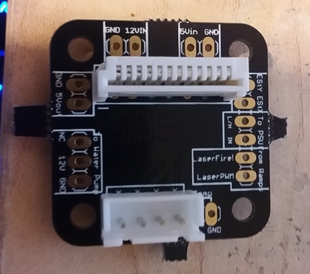
@Yuusuf_Sallahuddin_Y Sadly that was the problem. Fortunately I didn’t fry the board. Y axis works!!! X axis, moves back and forth in stead of stepping. This is what I have wired up for the middleman board. Did I flip something?
@Jerry_Hartmann Not 100% certain, but there are numbers on the middleman board where the ribbon cable connector goes & there is a 1 (or maybe it was a 12) on the square patch on the ribbon connector. Just checked my old photos & it seems you wired the ribbon connector correctly. With the X axis moving back & forth I can’t say for certain what would cause that as I am a total nongineer  Hopefully someone else like @Scott_Marshall can pipe up on that issue.
Since you have it working to some degree, much of this is satisfied.
Is the “Back and Forth” a shudder, or does it move a distance and reverse? If it shudders, you may have a phase reversed, try reversing wires 1 and 2 and see if that helps.
Also verify all 4 of the conductors and make sure they are solid from the Smoothieboard connector to the motor. An open wire on one winding will also make it vibrate or Shudder,
If it actually moves (> 1/4") and reverses it’s probably running, but is being reversed by the Smoothie. This can be caused by open endstop switched to reversed endstop logic. Again, compare to the settings below (ENDSTOPS SECTION).
One more possibly is if you have the current setting too low or high, or the motor is bad or jammed, The Allegro Stepper Drivers on the Smoothieboard may be shutting down and re-starting.
Compare the “MOTOR DRIVE SECTION” below to yours and look for any substantial difference.
Make sure you shut down and reboot after each Config change.
.
I’ve created a “easy” Config file (see below) that has built in instructions and has most of the unnecessary sections (like for 3d printers and battlebots) removed.
You cannot use Wordpad or the like to edit it, they will corrupt it and it will not work properly. (Microsoft adds it’s own file tags which are not visable but interfere with it’s operation)
Use Gedit to edit the Config, it’s free and easy to use.
Send me an Email, and I’ll send you my ACR module instuctions and the Config file that should copy right in.
As Yuusuf suggested, make sure you have 24v going to the VBB line of the Smoothieboard (last Red light on) or the motors won’t run.
Here’s a text version of the ALL-Tek ‘user friendly(er)’ Config file
#23456789012345678901234567890123456789012345678901234567890123456789012345678901234567890123456789C (+32 character linit)
#------------------------------MOTOR DRIVE SECTION---------------------------------------
#X Axis
alpha_step_pin 2.0 # Pin for alpha stepper step signal
alpha_dir_pin 0.5! # Pin for alpha stepper direction
alpha_en_pin 0.4 # Pin for alpha enable pin
alpha_current 0.6 # X stepper motor current
alpha_max_rate 30000.0 # mm/min
#Y Axis
beta_step_pin 2.1 # Pin for beta stepper step signal
beta_dir_pin 0.11 # Pin for beta stepper direction
beta_en_pin 0.10 # Pin for beta enable
beta_current 0.5 # Y stepper motor current
beta_max_rate 30000.0 # mm/min
-Speed
microseconds_per_step_pulse 1 # Duration of step pulses
# to stepper drivers, in microseconds. This is the width (duration) of the Step pulse sent to
# the Allegro A4982 Stepper Motor Controller Chip.
#
base_stepping_frequency 100000 # Base frequency for stepping - this is 100000 steps per second.
# X and Y axis speed limits
x_axis_max_speed 30000 # mm/min
y_axis_max_speed 30000 # mm/min
#
#-------------------------------DRIVE RATIO SECTION---------------------------------------
alpha_steps_per_mm 157.575 # Steps per mm for alpha stepper
beta_steps_per_mm 157.575 # Steps per mm for beta stepper
#------------------------------LASER MODULE SECTION--------------------------------------
laser_module_enable true # Always true for K40
laser_module_pin 2.4! # Pin 2.4 (inverted output)
laser_module_maximum_power 1.0 # Max power limiter
laser_module_minimum_power 0.0 # As with Maximum Power,
laser_module_default_power 1.0 # Sets the PWM output level
laser_module_pwm_period 20 # This sets the length of time
#----------------------------------ENDSTOPS SECTION---------------------------------------
endstops_enable true # Endstops Operational
alpha_min_endstop 1.24^ # X Axis Enabled Positive
alpha_max_endstop NC # X Axis Max, NOT USED
alpha_homing_direction home_to_min # Direction to search for
alpha_min 0 # Automatically loaded after
alpha_max 200 # Automatically Loaded after
beta_min_endstop NC # Y Axis Min, NOT USED
beta_max_endstop 1.27^ # Y Axis Enabled Positive
beta_homing_direction home_to_max # Direction to search for
#---------------------------ENDSTOP AUTO-CALIBRATE SECTION-----------------------------------
beta_min 0 # Automatically loaded after
beta_max 200 # Automatically loaded after
alpha_max_travel 325 # Maximum Endstop Seek Distance
beta_max_travel 225 # Maximum Endstop Seek Distance
alpha_fast_homing_rate_mm_s 60 # Rapid feed rate for homing (X)
beta_fast_homing_rate_mm_s 60 # Rapid feed rate for homing (Y)
alpha_slow_homing_rate_mm_s 10 # Calibration approach rate (X)
beta_slow_homing_rate_mm_s 10 # Calibration approach rate (Y)
alpha_homing_retract_mm 10 # Distance head backs off for slow re-approach & calibrate (X)
beta_homing_retract_mm 10 # Distance head backs off for slow re-approach & calibrate (Y)
#endstop_debounce_count 100 # unneeded for optos,default is 100
#-----------------------------------MACHINE STOP SECTION--------------------------------------
kill_button_enable true # Button enabled
kill_button_pin 2.12 # Smoothieboard pin 2.12 (can use pin 2.11)Logic H to Halt processor.
#-------------------------AUX COOLING FAN/UTILITY OUTPUT SECTION------------------------------
switch.fan.enable false # Change to ‘True’ to enable port
switch.fan.input_on_command M106 # Call ‘M106 Sxxx’ for ON @ xxx speed
switch.fan.input_off_command M107 # Call ‘M107’ for OFF
switch.fan.output_pin 2.6 # Can use any available PWM capable outputs
switch.fan.output_type pwm # pwm output settable with S parameter in the input_on_comand
#switch.fan.max_pwm 255 # set max pwm for the pin default is 255
#-------------------------NETWORK (ETHERNET COMMUNICATIONS) SECTION---------------------------
network.enable false # enable the ethernet network services
network.webserver.enable true # enable the webserver
network.telnet.enable true # enable the telnet server
network.ip_address auto # use dhcp to get ip address
#----------------------------USB (SERIAL COMMUNICATIONS) SECTION------------------------------
uart0.baud_rate 115200 # Baud rate for the default hardware,
second_usb_serial_enable false # This enables a second usb serial port - allows use of both
#msd_disable false # disable the MSD (USB SDCARD) when set to true (needs special binary)
#dfu_enable false # for linux developers, set to true to enable DFU
#watchdog_timeout 10 # watchdog timeout in seconds, default is 10, set to 0 to disable the watchdog
currentcontrol_module_enable true #
#---------------------------CUSTOM MENU SECTION-------------------------------
custom_menu.power_on.enable true #
http://custom_menu.power_on.name Power_on #
custom_menu.power_on.command M80 #
custom_menu.power_off.enable true #
http://custom_menu.power_off.name Power_off #
custom_menu.power_off.command M81 #
#---------------------------FUNCTION SETUP SECTION-------------------------------
#This is setup and Accel/Decel curve controls. Leave it alone unless you know your way around in here.
default_feed_rate 4000 # Default rate ( mm/minute ) for G1/G2/G3 moves
default_seek_rate 4000 # Default rate ( mm/minute ) for G0 moves
mm_per_arc_segment 0.0 # Fixed length for line segments that divide arcs 0 to disable
mm_max_arc_error 0.01 # The maximum error for line segments that divide arcs 0 to disable
planner_queue_size 32 # DO NOT CHANGE THIS UNLESS YOU KNOW EXACTLY WHAT YOU ARE DOING
acceleration 3000 # Acceleration in mm/second/second.
#z_acceleration 500 # Acceleration for Z only moves in mm/s^2, 0 uses acceleration which is the default. DO NOT SET ON A DELTA
junction_deviation 0.05 # Similar to the old “max_jerk”, in millimeters,
# see https://github.com/grbl/grbl/blob/master/planner.c
# and Configuring Grbl v0.8 · grbl/grbl Wiki · GitHub
# Lower values mean being more careful, higher values means being
# faster and have more jerk
#z_junction_deviation 0.0 # for Z only moves, -1 uses junction_deviation, zero disables junction_deviation on z moves DO NOT SET ON A DELTA
#minimum_planner_speed 0.0 # sets the minimum planner speed in mm/sec
Scott
@Scott_Marshall Woo! Went to try to swap cables and found out 2 of them had come loose in their housing. Recrimmped and X/Y are working great.
Follow up, am I good to go now? Will the test fire and power controls work through the ribbon or am I going to have to follow along in the PWM thread?
You should be ready to test.
Disconnect the wire from pin 2.4 (if that’s the one you are using - seems most popular) and verify it’s @ 3.3v while idling (Smoothie booted up but not running a program)
Remember the K40 PSU requires an inverted Laser Operate signal, you should have an ! after your pin number in the config file (example - 2.4!)
Be careful while doing this, since it requires a zero volt signal to fire, the laser can fire unexpectedly if something’s not right.
Then run a cut program and see if it drops to zero while cutting.
You’ve then verified the Smoothie is doing it’s job.
Re-connect and try to burn something.
Use a simple outline or shape in .svg for starters.
If it works OK there, it should PWM when called to by your cutting software.
If you DON’T get a cut, look to your level translator circuit and verify it’s working properly (same test as above but you should see +5v idle and 0v on the output (pin 4 of the PSU power connector)
Good luck!
Scott
Safety Mod:
The Smoothieboard takes awhile to get booted up and running it’s code, but the K40 PSU is capable of firing the laser much faster, so during the interim period, the laser CAN fire at random.
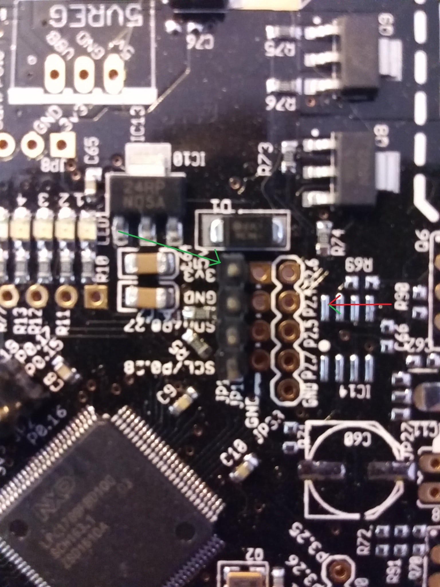
I recommend adding a 15k pullup resistor from pin 2.4 (or your LO pin of choice) to the 3.3v source on the Smoothieboard (there’s a handy pin right next to the processor - there’s a 6 pin header, it’s the lower left pin and is marked 3v3)
This will hold the output of the Smoothieboard high (off) until it gets done booting and prevent the laser from firing due to noise.
Once the Smoothie has taken control, the resistor will have no effect.
What about the panel controls? Power knob test fire? If I leave the laser switch off until boot, I shouldn’t need the resistor, correct?
@Jerry_Hartmann I believe you are correct on leaving the panel Laser Enable switch turned off until the smoothie is fully booted, as I noticed if I had mine switched on when booting it would blast a beam at the cutting area quickly, but then stop. When I don’t have Laser Enable enabled it doesn’t do this. Scott can verify in a more engineery way though
Leaving the “LASER SWITCH” as they label it off will disable the power supply, preventing the burst at startup.
The resistor is just a safety precaution and another layer of protection (and I heartily recommend it, I’d gladly pay the $0.15 NOT to have a laser burn (or worse))
It just may prevent an accident if you slip up and forget the switch, or any of a bunch of things that can conspire to get you. Accidents are almost never caused by a single thing, they are the result of several things all going wrong at the same time.
Eliminate all that you can predict, and hopefully those precautions will give you some ‘breathing room’ for those you cannot.
If I seem overcautious, it’s because I spent years designing controls for devices that melt 50 tons of steel, or pick up rail cars, and that sort of work gives you a wholly different design approach than a lot of folks have. I never had one of my machines hurt someone, and don’t want to start with a table top laser cutter.
I have a replacement laser fire cable going out to people who bought an ACR before I implemented the resistor upgrade, it replaces the stock cable in 2 minutes.
If anyone out there wants a FREE fire cable with built in resistor (plugs onto the smoothie board, no soldering required) just message me on my website or send me an SASE envelope. Offer good to anyone running a board that needs it, not just ALL-Tek customers.
Scott
@Scott_Marshall so test fire works. And the board relays svg files just fine, but the laser does not fire during movement.
I’m guessing it’s because L isn’t connected to the board but for the life of me I can’t find where it’s supposed to be wired in
L on the PSU is the Fire line. It’s 5V negative logic (0v fires the laser 5V turns it off).
This needs to be connected to a Smoothieboard output pin (most people use 2.4) and the proper Config changes made for it to function.
A level translator circuit is required between the Smoothie and the PSU because the Smoothie uses 3.3v logic while the PSU uses 5V logic. If hooked up directly, the laser won’t be turned off safely.
This is the “tricky” part of the install.
Chinese level switchers are available online, you can build your own, or get an ACR board, plug it in and be running in 15 Minutes…
That will do the job, It’s similar to the Chip I use, The TI 74LVCT45.
The discrete ones using FETs work fine too.
Scott
Do I need to wire up a pin connector for P2.4 or use the 3.3? Is there already a thread covering this so I don’t keep asking things that have been asked?
@Jerry_Hartmann On mine, I soldered on some pins to that set of 5. Figured I may as well do all 5 in case I needed a different one later on.
@Jerry_Hartmann Honestly, I have no idea what that means. I used one of @Scott_Marshall 's ACR kits to attach my smoothieboard to the k40. So mine goes 2.4 to ACR to PSU I think. From my understanding of what Scott explained, the L on PSU requires 5V to shut it off completely. So I think you need to go pin 2.4, step up to 5V, then to L. Don’t take that as gospel however, as I barely know what’s going on.
edit: also, mine doesn’t use any GND on the Pin 2.4 thing… I have that wire (from ACR) hanging loose. But, maybe the ACR uses a GND somewhere else.
You may find some useful information in my spaces that I set up for documenting my smoothie conversion. A lot of others have posted stuff in there too. https://spaces.google.com/space/379777357