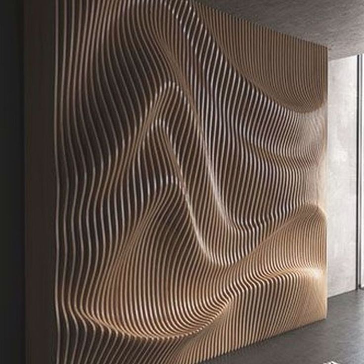
Hey everybody. Hope this winter is treating you well. Now that I’ve been frozen out of my shop for a while I’ve been nosing around the net for some new ideas and came across what was probably a more popular art form in the 70s, but is still quite captivating…parametric wall art design (pic below)…which of course led quickly to studying the gorgeous CNC machines that produce these designs and their associated software.
I like the tiling feature the X Carve Pro offers but I haven’t read about it being offered on any other CNC machine. What Inventables calls ‘tiling’ is where you can cut pieces larger than your CNC table by sliding your wood/material through and let it do one section at a time.
Is there any way to make the AVID PRO 510 do this tiling function or is this something only Xcarve has right now?
V Carve Pro is SO expensive! Is there ANY way to get it cheaper than it’s retail price? I’ve seen where you can get an activation code if you’re part of an educational group, so wonder if that could be cheaper. Also, would be nice to be able to split a subscription with someone.
I believe I’ve seen where Fusion 360 was suggested as a good program to use if you’re working with parametric designs. Any opinions on this?
And last, I’m still searching for the best forum to ask these kinds of CNC and software questions. If there’s a more appropriate place than here please do let me know.
This parametric design is where the value at one axis is a function of the other two axes. Usually when you see “parametric design” people are thinking of static parameters you can change. I don’t think that every design tool is capable of that. Yes, Fusion 360 can have functions for parameters but I have no idea whether you have enough information available to the function to make that calculation.
Thinking about those example pieces from the picture you posted, and cutting them sticking through a router, X would be a parametric function with respect to X and the number of the section times the pitch of the sections. The pitch would be a static parameter (say, 24mm because you chose 12mm plywood and have a thin spacer at the base between each section). The X value would depend on the Y station, which would vary as it went along.
If you have some coding background, it might be easier to write a program to generate the gcode for those cuts directly than to work through a workflow to use existing tools. That might sound like a stretch! But it’s not much more programming than writing the function for a parameter in a CAD tool. This is almost certainly the route that I would take if I were making this kind of art. Is this something you’d want to know about?
Looking more closely at the picture, it’s not 100% certain that the X value is a function of Y. Near the bottom it looks like it might curve back on itself, so that the line that is carved doubles back on itself. If anything you want to carve has an edge like that, whether you are writing a program to generate gcode or are writing a functional parameter in CAD, it will require a different approach.
If you want to follow paths that aren’t proper functions, you might want a different approach. You could have constraints for control points for b-splines where the locations of all of the b-spline control points are functional. That could enable curves that double back on themselves. I’m pretty sure I understand how that could be done in FreeCAD, and expect that you could do the same in Fusion360 but don’t have experience there.
Anyway, want to share more about your background knowledge here? Do you have a coding background? Math background? Does what I am saying about whether a line is a function make sense to you?
My attempts at this would be to model this in 3D either in FreeCAD or OpenSCAD.
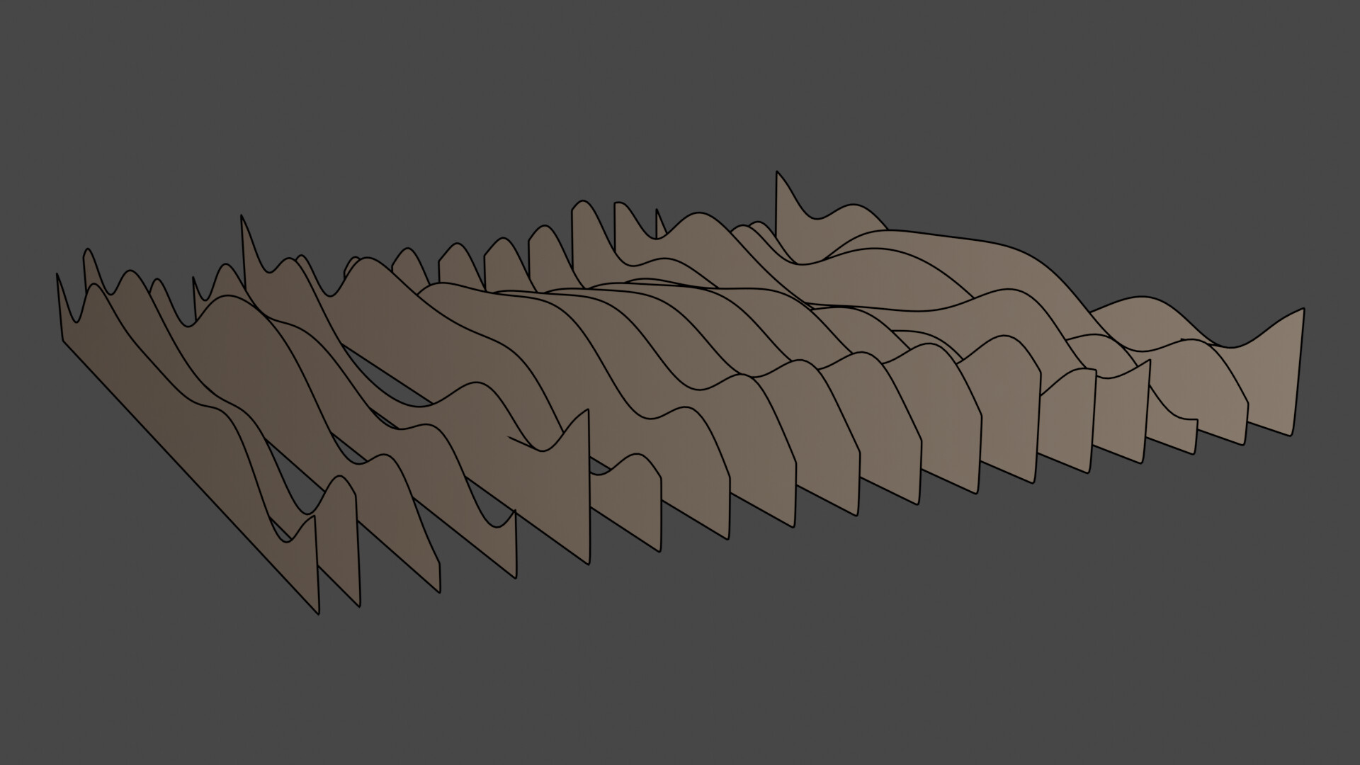
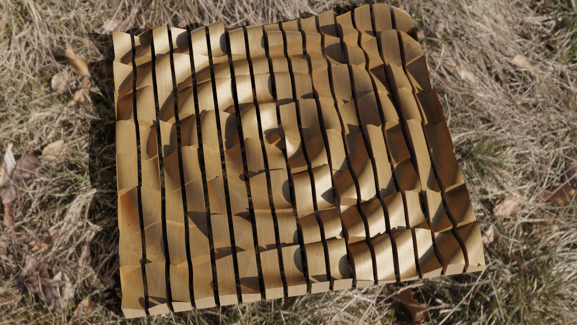
With the 3D model I would rotate it on end(around the X axis in the photo) and then try using a slicer to slice that into pieces where you’d delete every other slice to produce the assemblies to back into what you see above. With these sliced 3D models I would attempt to use something like LightBurn or another 2 axis laser cutter software to generate the toolpaths for each section. Since they are longer than your CNC machine, LightBurn has a feature for registration marks to have along the way so you’d cut, zero, move the piece and cut the next part of the length.
That’s my $0.02 at 6:00a and only half a cup of coffee. And because you’re removing 1/2 the sections, you’d stretch the model in the Y axis 2x.
I hope you create a thread on this and keep up informed of your progress and design choices.
Thanks for the help guys. Wish I was coming to the table with more general knowledge of CAD design, etc than I am but as it is I’ve got a plain old college education in the sciences but no practical experience with any of this. I’ve been absorbing some info for a while and as far as I can tell there’s not a whole lot of info to be had on exactly how to accomplish a piece like this. I’ll have to find the video again but the one that’s explained it the best included a step with the image was sliced and every other piece was removed as doug1 suggests. I’m sure there’s a way to do this using existing software, and not having to write any code, I just haven’t figured it out yet.
I’m wondering whether Kiri:Moto could do this slicing well? It has a laser mode for creating slices of a volume to laser-cut, and if it doesn’t work for CNC yet I would expect it to be something Stuart would be interested in adding.
I’m also coming from 3d modeling software. But there are several ways to create and split the model for a pattern (at least manually).
Just from the top of my head:
Booleans (Cutters)
polygonal modeling deleting unwanted parts
Selecting and separating needed profiles
line array with conforming profiles to existing surface
STL slicers (cnc software)
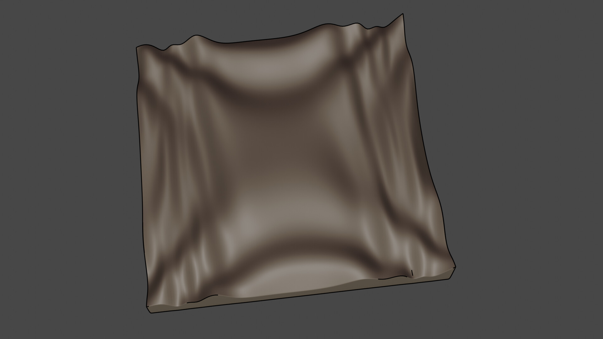
As an example for this surface:
1 - sin( x3 + y)+cos(y2-x**2)
Darren Stone just dropped a video about how to do this in FreeCAD where he improves someone else’s design, and said that he’s going to do another one on how to create them from scratch.