I noticed you uploaded a new compact carriage and XY side carriage components. I printed them, and was curious if you had any feedback, negative or positive.
I want to switch from Walters’ Mini Space Invaders carriage to something a little easier to work on, has better cable support, and provides easy access to the hot end.
I will be honest, I designed it for the group, but never utilized it myself. I know a few have had good luck with it. My opinion on it is, I would like the cross rods to cross closer to the centerline of the axis of the nozzle for stability, but geometry of the Extruder limits this. I would love some critical feedback on improvements I could make. Note the carriage is designed to use heat set inserts in a few places, which gave some people issues to source depending on their location.
I know CNC kitchen on YouTube made a good video about them recently. And there are a few sellers on AliExpress that started selling the nice ones.
I have found the ones at Trimcraft to work really well. They appear to be real, OEM EZ-Lok’s. Gino’s prices are fair I think. I got 100 pcs of the double fins from McMAster too.
You also want to try and taper the bores to seat these in. Look at the E-Z Sonic data sheets for geometry. I have had the best luck with respect to location and pullout by making a trancated cone of the OD’s D & S for overall length.
All I can tell you is when I try to recycle a part and pull the inserts out, its a real b*$ch to pull them.
I also use a piece of metal as a heatsink of sorts to put over the insert when I set them- even a v6 heatblock set on top of the part to keep the insert seated and pull the heat ‘out’ of the insert and keep it flush at the top.
Hey Eric,
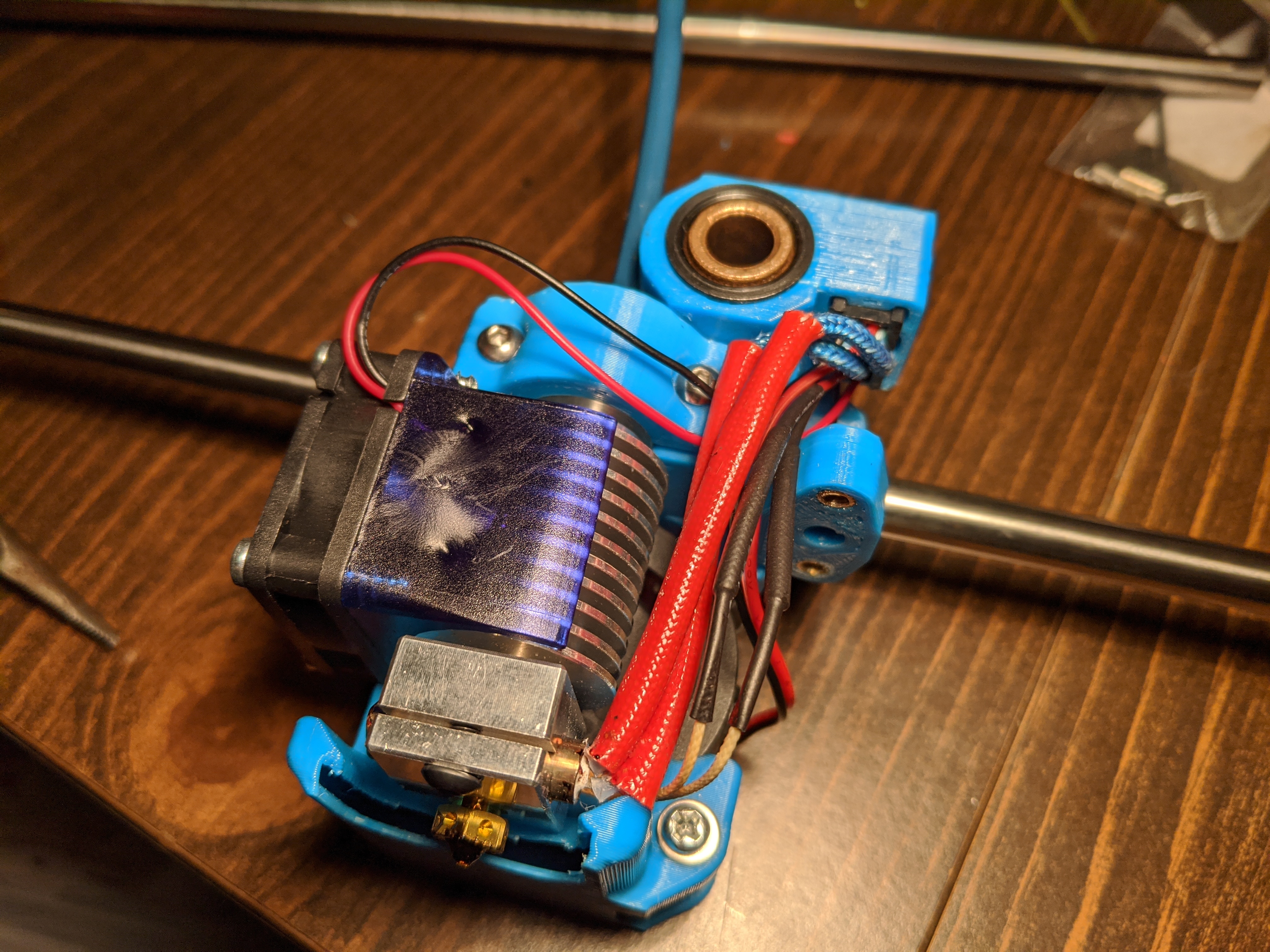
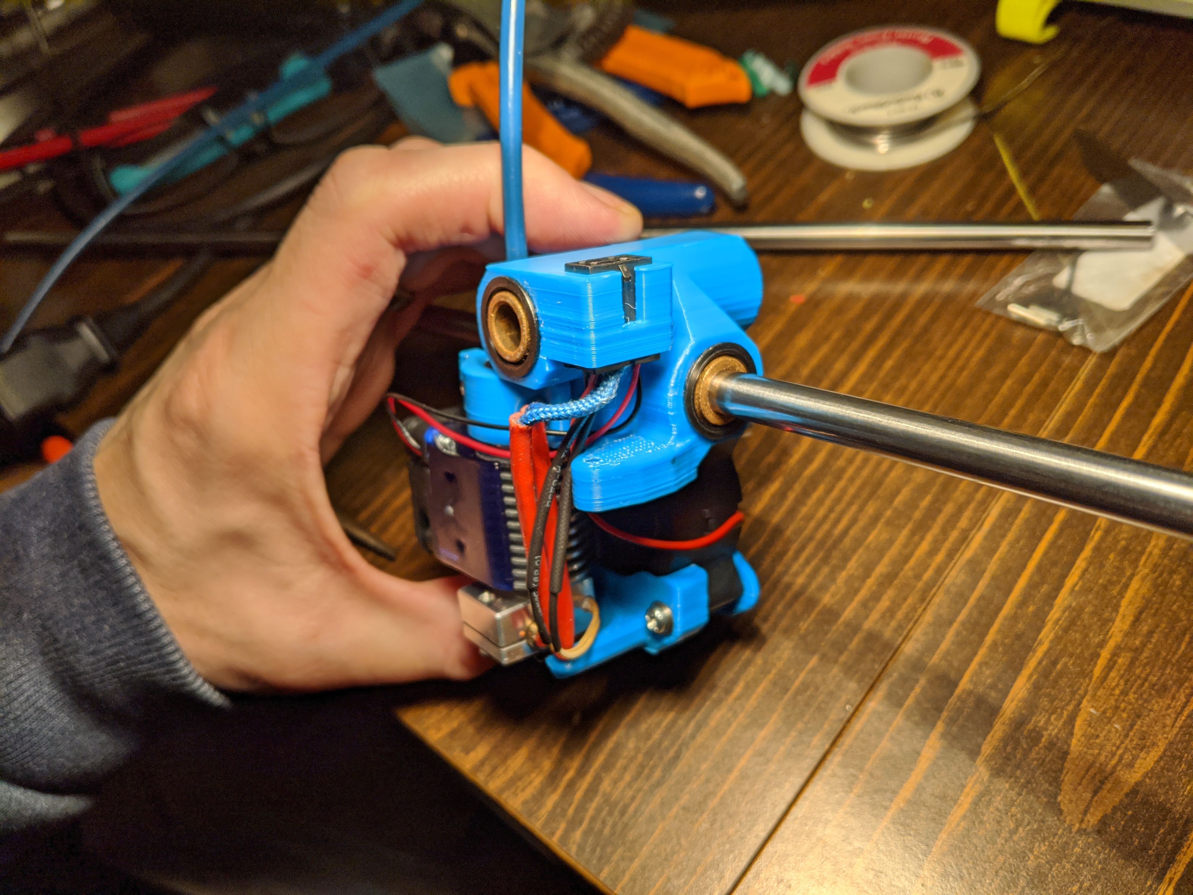
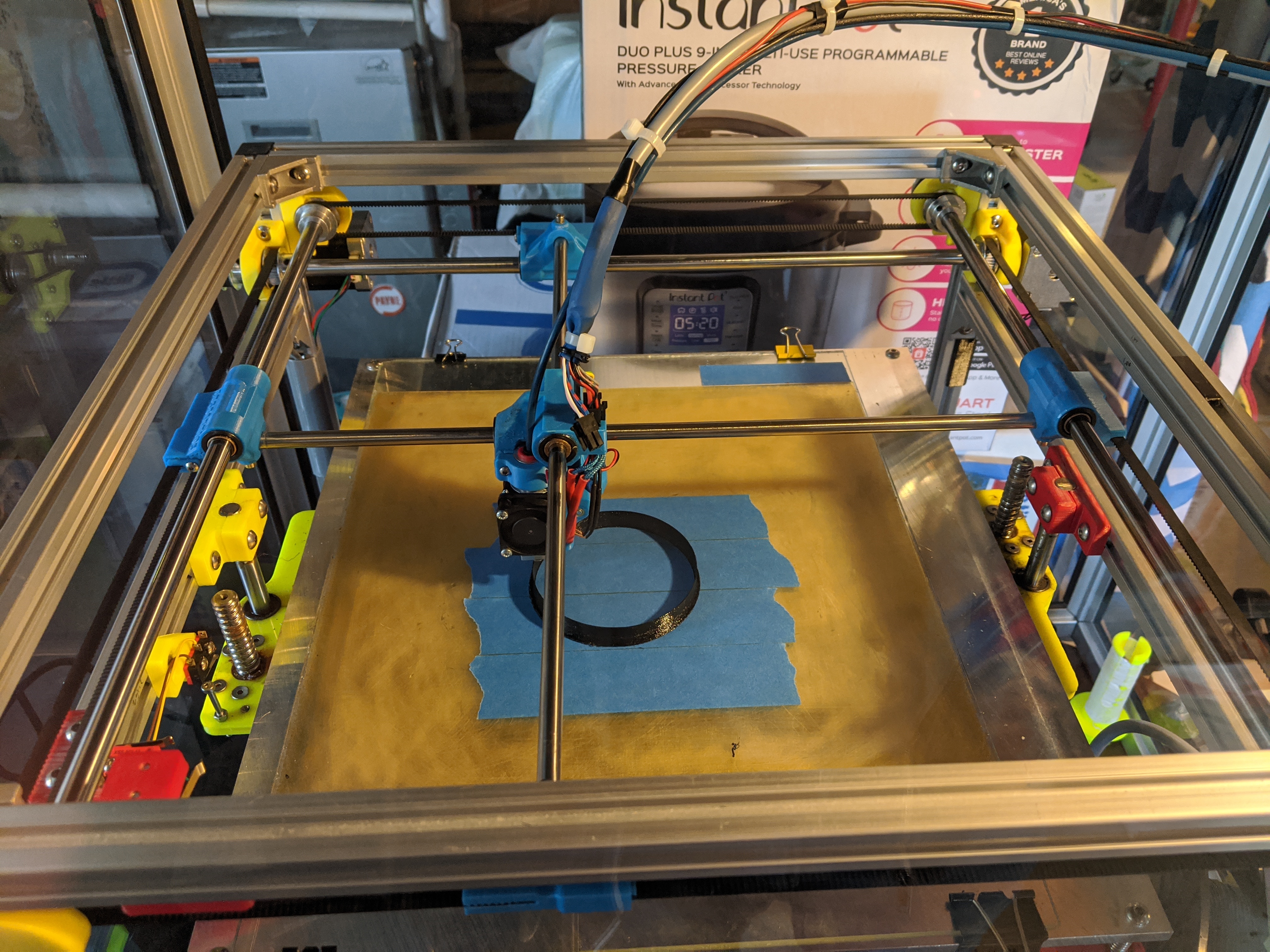
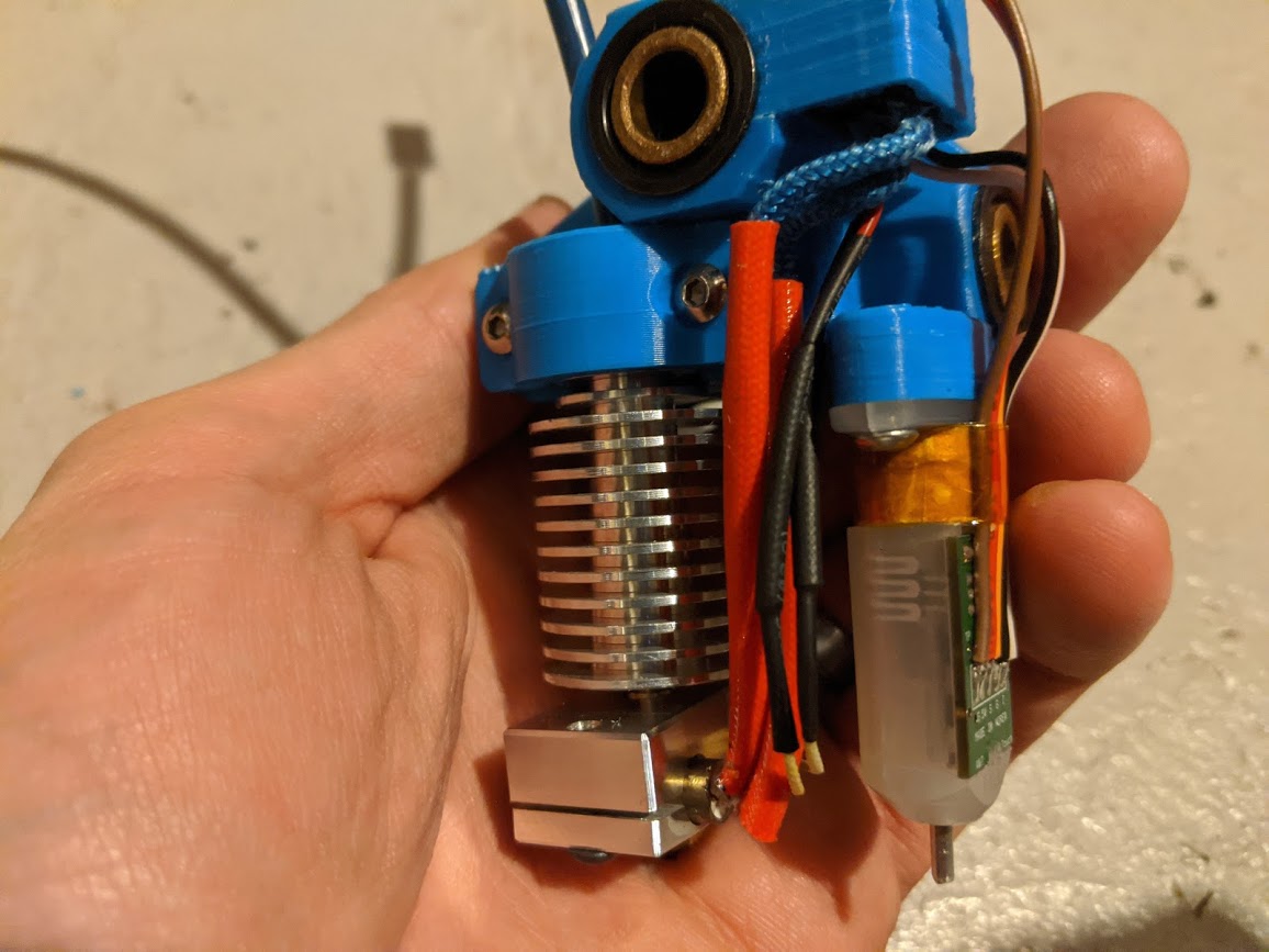
I have my printer pretty well disassembled, including all electronics ripped out and carriage and XY mounts disassembled. I was about to assemble and realized there are heat set insert spots in the X Y carriers. I am assuming these are sized for M4, but wanted to confirm. I am also adding a sneak peak of my assembled carriage with Microfit connection! I tired doing microfit a few years ago but gave up and made an ugly collection of wires and soldered joints instead.
I finally ordered a a set of PA-09 crimpers and they work wonderfully for Dupots and molex connectors.
As far as design of the compact carriage, I would make the holes deeper for the press fits and allow for expansion of melted plastic/pass through of screws. The top of the BL touch mount should be angled slightly. When trying to install the microfit connector there is next to no room, and as a consequence the wires get bent pretty severely going into the connector mount
On a complete side-note I am not a huge fan of the Acetone press fit technique and wish this was more of an epoxy connection. y prints always split just a little bit when the bushings are pressed in, no matter how much I ABS soften the surface. Additionally I understand that ABS decreases the strength of ABS plastic.
I know what you mean about the tight wire routing. It’s doable… but requires adding some serous bend into the wires. I thought about spreading things out… but figured compact carriages main point was to increase printable area, so I left it really compact.
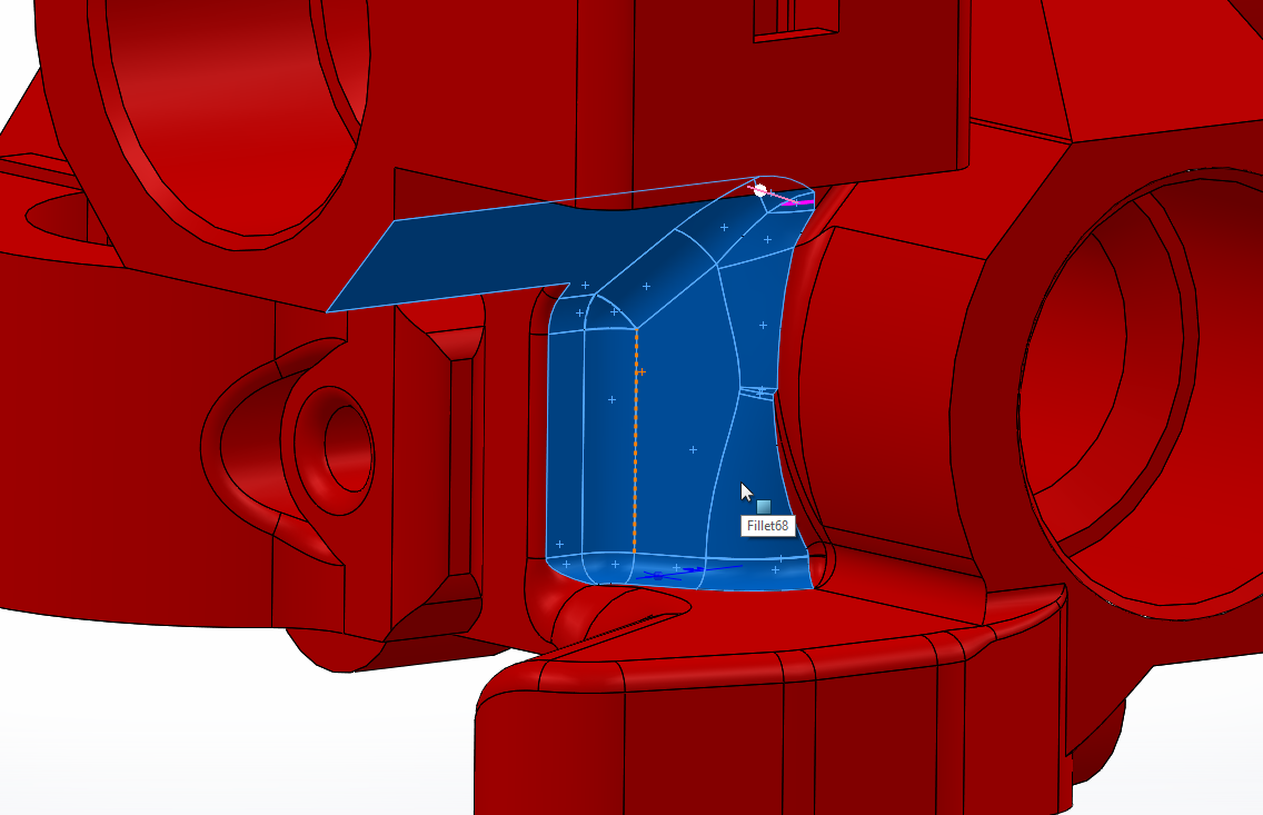
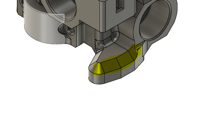
What area do you think sloping could help? I can get that added to the model. If I roll over this edge, and open up the pocket underneath… would that help?
All my heat inserts were M3. There are so many varieties of those inserts (different ID/OD/Depths). I should probably call out the ones I use with some notes. But I think I can increase the space below the inserts for thermal squeeze out during insetting. That being said my inserts are tapered m3 heatset… so I had almost no squeeze out during install.
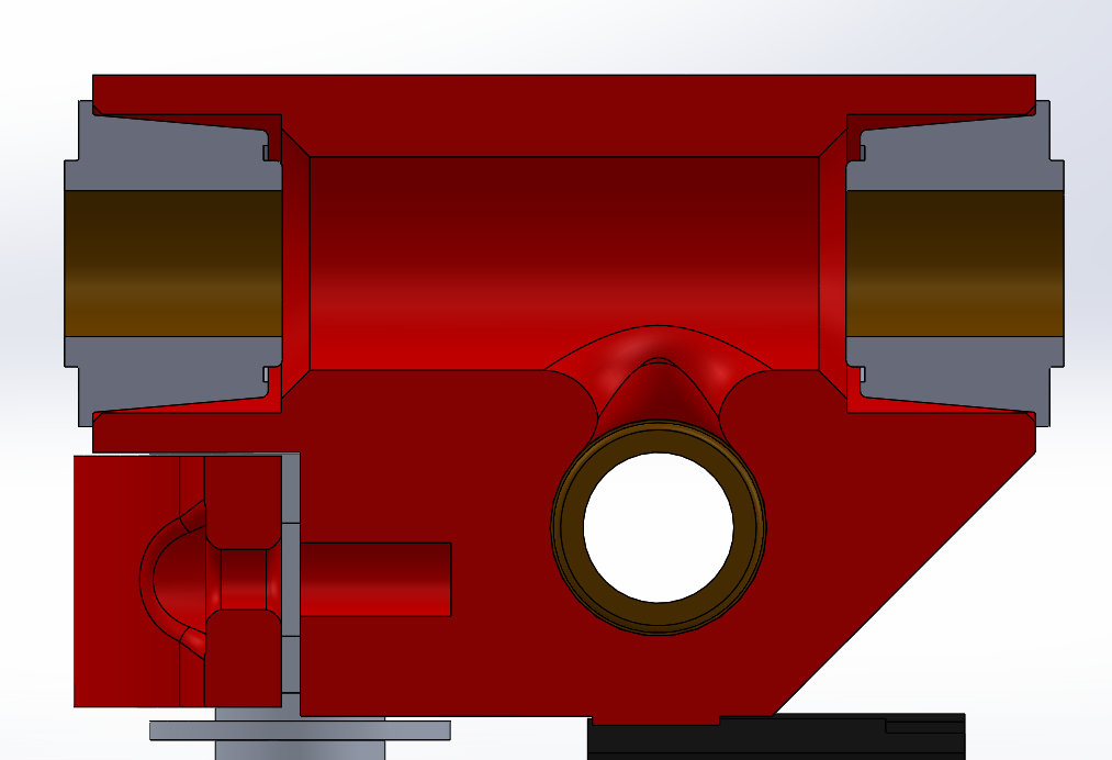
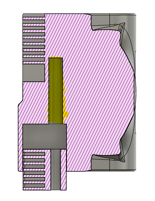
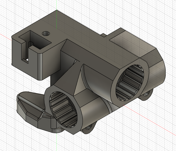
For the bushings, I could make a version with larger bushing holes or some glue channels for epoxy-in methods. Just need to be careful not to get the glue in the self aligning portion of the bushing. Plus if the part is to dimension… it should have room for some glue as designed (See Picture)
Sorry for not responding for a while, was on a business trip. The M3 type inserts I was using were cheap chinese ones with a straight knurl on both sides. I have since purchased some tapered ones with a little more sophisticated geometry, these appear to seat a little more firmly in the XY carriers.
The tight wire routing is actually for installation of the molex fitting (or removal).
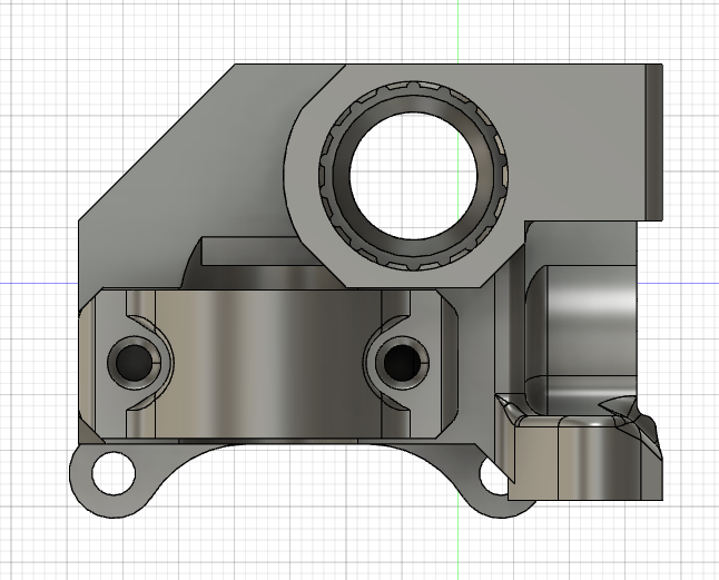
I added a chamfer, see above image. It might be too much as it appears to be close to interfering with press-fit holes. Ideally the chamber should only go on the outside edge to facilitate the molex sliding in at an angle.
On a side note, the XY carriage assembly needs M3 pressfit deep into the housing correct? How deep did you go?
Lastly, instead of reprinting the carriage I was going to try heat setting the bushings instead of ABS. Have you ever tried this? Heating up the bushing like you would a press-fit insert? I would hope this would reduce the stress on the layers as ABS is pretty damaging.
Insert doesn’t go deep in the hole. The extra depth is for bolt clearance after the insert for threading in the bolt. For the self alignment bushing don’t heat it. It’s epoxy potted internally for the spherical joint. Heating it will crack the epoxy… Ask me how I know that tidbit of knowledge
Thanks for that tidbit of info, I thought I remembered reading they were epoxy set, glad I asked. I’ll just stick with and method for now. I just finished inserting the m3 inserts, they went in nicely, so the holes are perfect as they are. I will probably go back and pull out the low quality inserts to prevent headaches in the future, especially for the hotend mount.
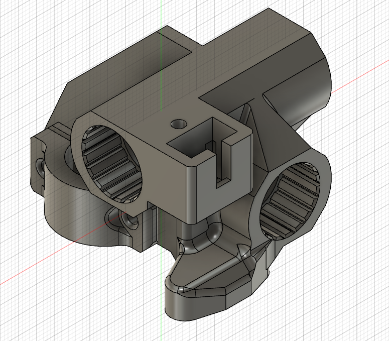
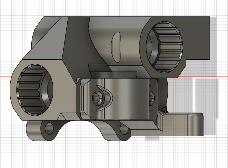
So I finally gave up on the carriage I printed, it seems askew. I was unable to get the pressed in bearings/rods perpendicular so the resistance of sliding the carriage was very difficult and probably wouldn’t move if I tried to force everything. I modified the carriage slightly to allow for epoxy of the bearings, and a little more clearance of the molex fitting. I’ll try and upload a few screen shots later tonight.
Absoultely these additions will be added to the github. I want to test it first to determine these changes function. I need figure out a makeshift enclosure to be able to print ABS for our MK3S printers at work. Unless someone wants to print one for me here I can pay if it’s reasonable.
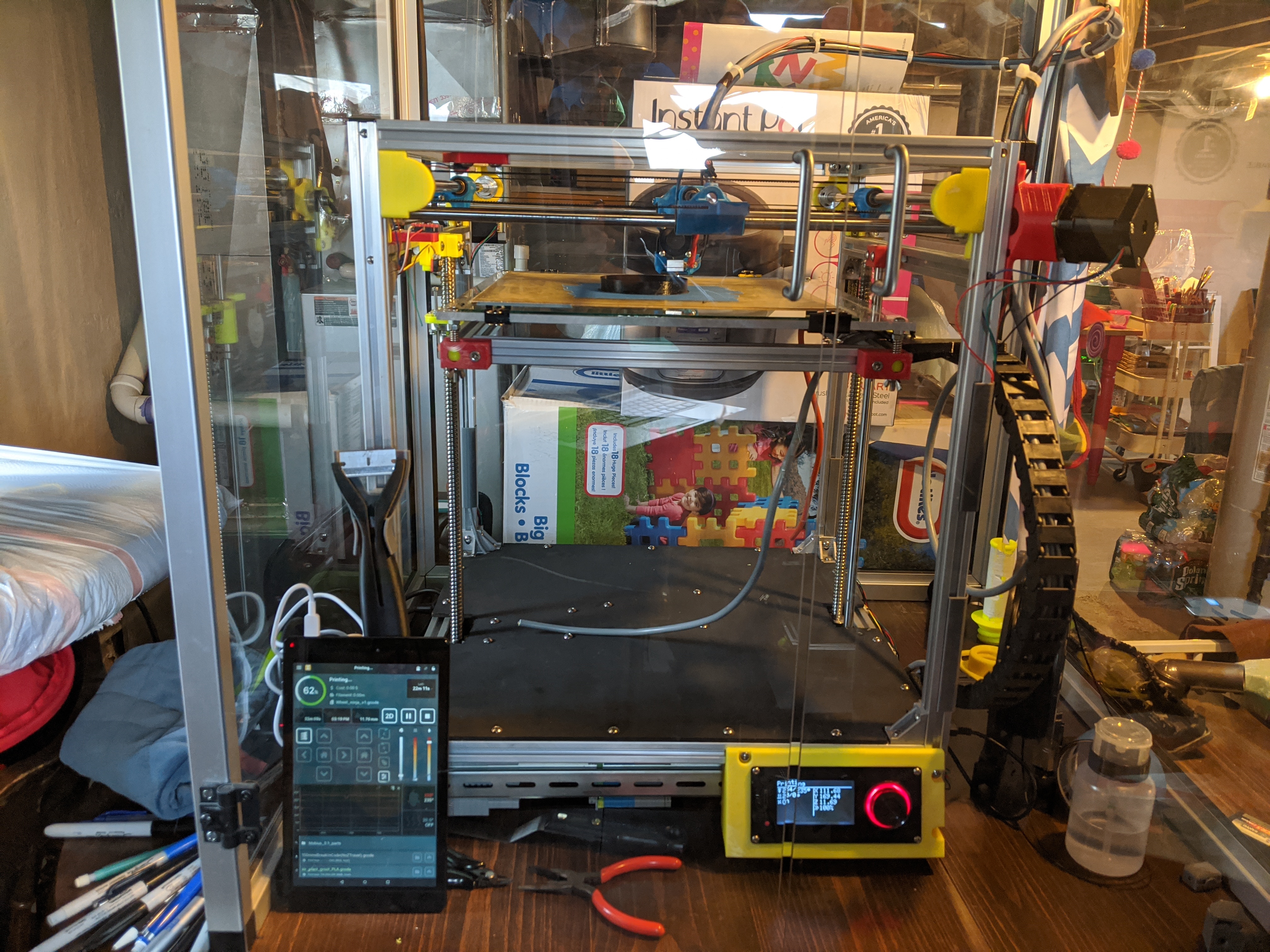
I’ve been inspired by some of the excellent build and designs on the Voron Discord, and the fact the my wiring has been completely ganky for years now I don’t want my toddler reaching into my printer and grabbing mains power. I would build a voron but can’t justify spending another ~$1500 when I have a very capable printer that just needs some tlc. I have been rocking their Mobius 3.1 extruder, which is an absolute tank, highly recommend. I have been very happy with the printer thus far.
Total modifications include:
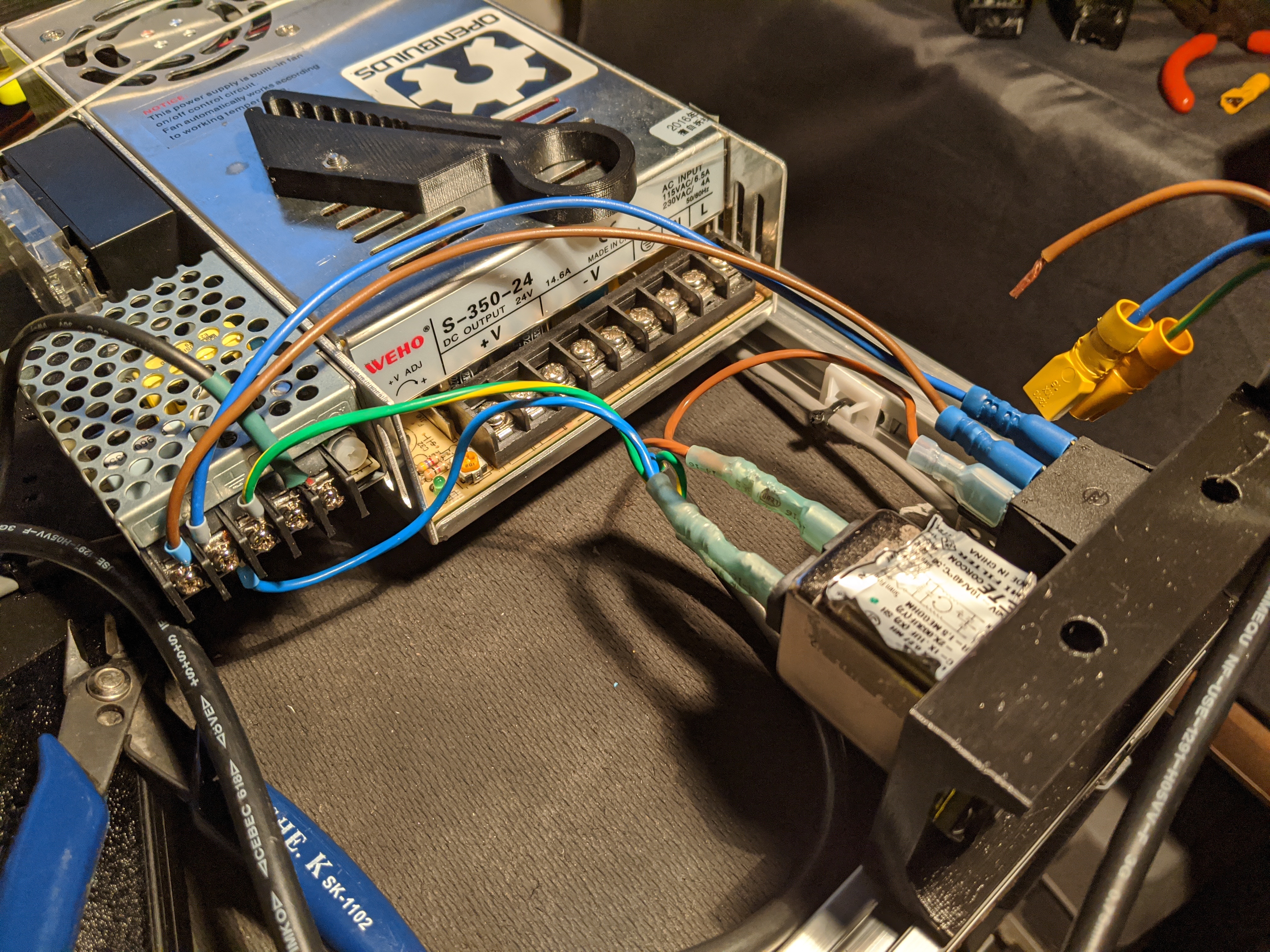
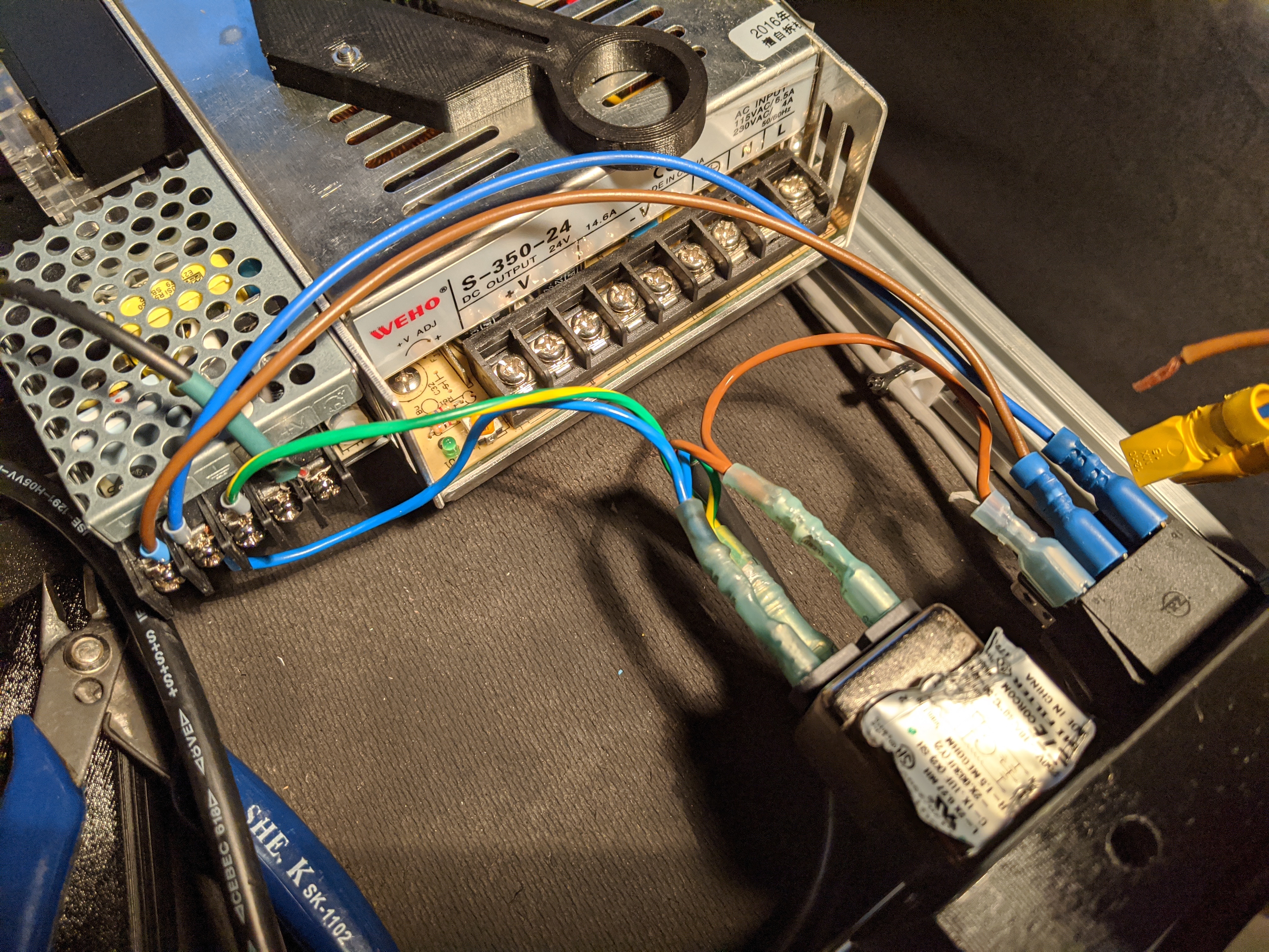
DIN rail for Mains (120V) and 24V
Dedicated 5V meanwell PS for Rasp Pi
Filtered Mains inlet (the one in the Eustathios BOM melted on me and scared the hell out of me), I altered the Voron design slightly to allow for a different switch along with their recommended filtered mains outlet.
Thermal cut-off fuse mounted to heatbed in the event of SSR failure
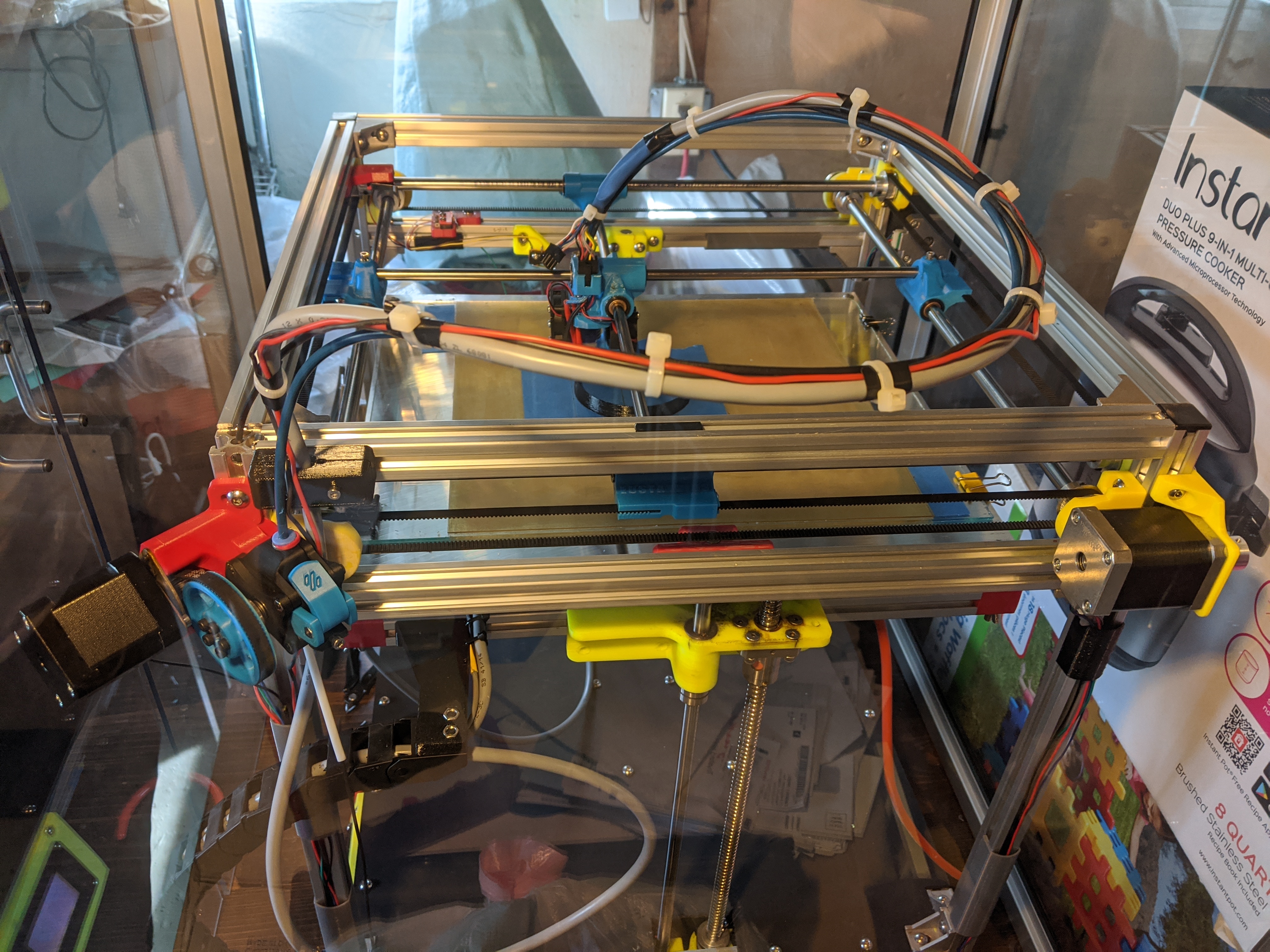
Secure wiring and support on carriage using molex with shielded 8 wires (from Eric), making for a cleaner more robust setup. New 3d printed mount on 2020 frame to secure carriage wiring. Added BLtouch using new carriage, just need to figure out how to set it up with Azteeg
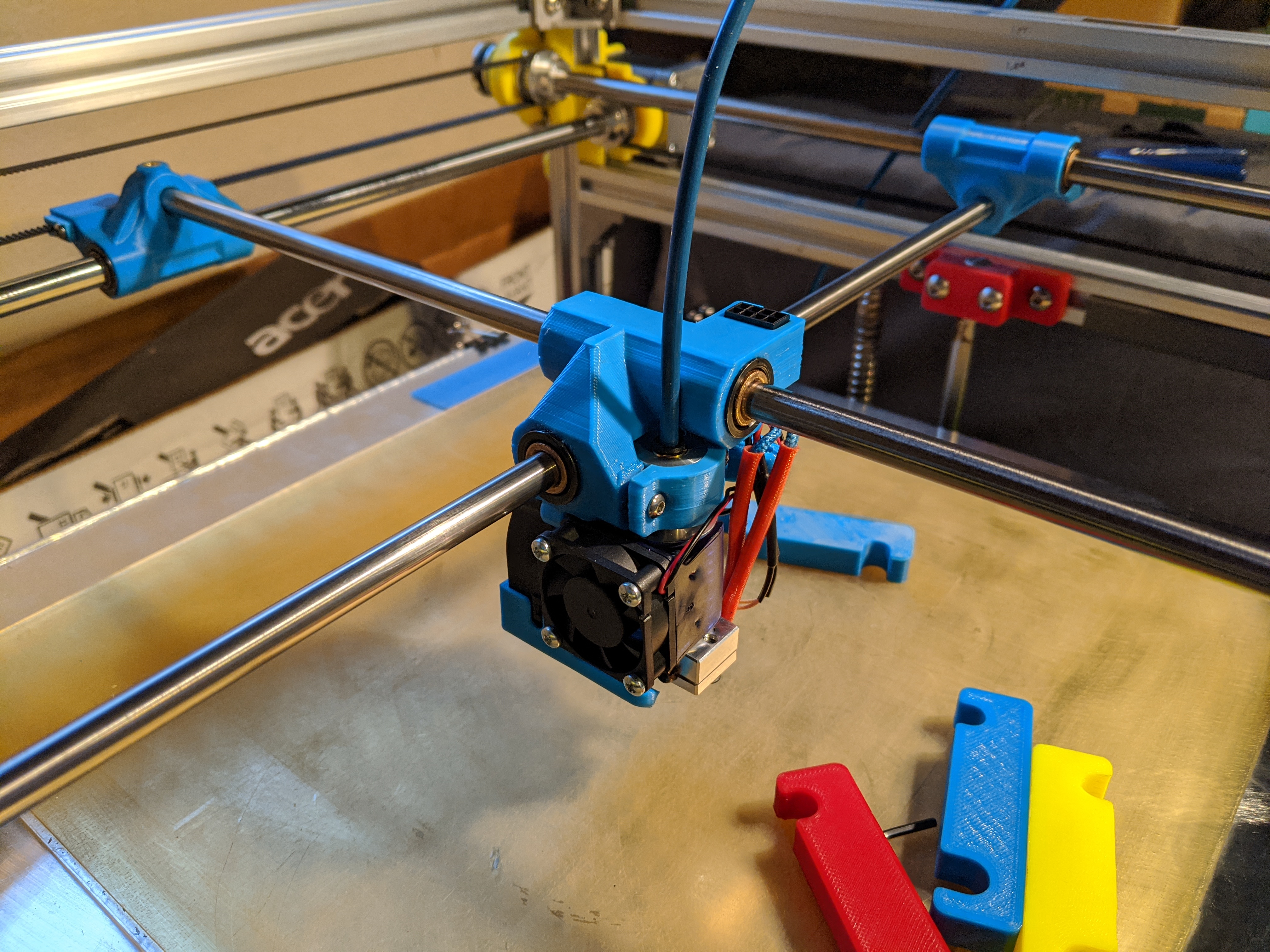
New 3d printed X Y gantry mounts from Eric, much slicker looking, and appear to be lower weight.
3d printed belt covers to allow for safe wiring without risk of belt touching wires, and provides ample area for securing of wires
Complete rewiring of end stops to reduce messy/loose wires using shielded wires
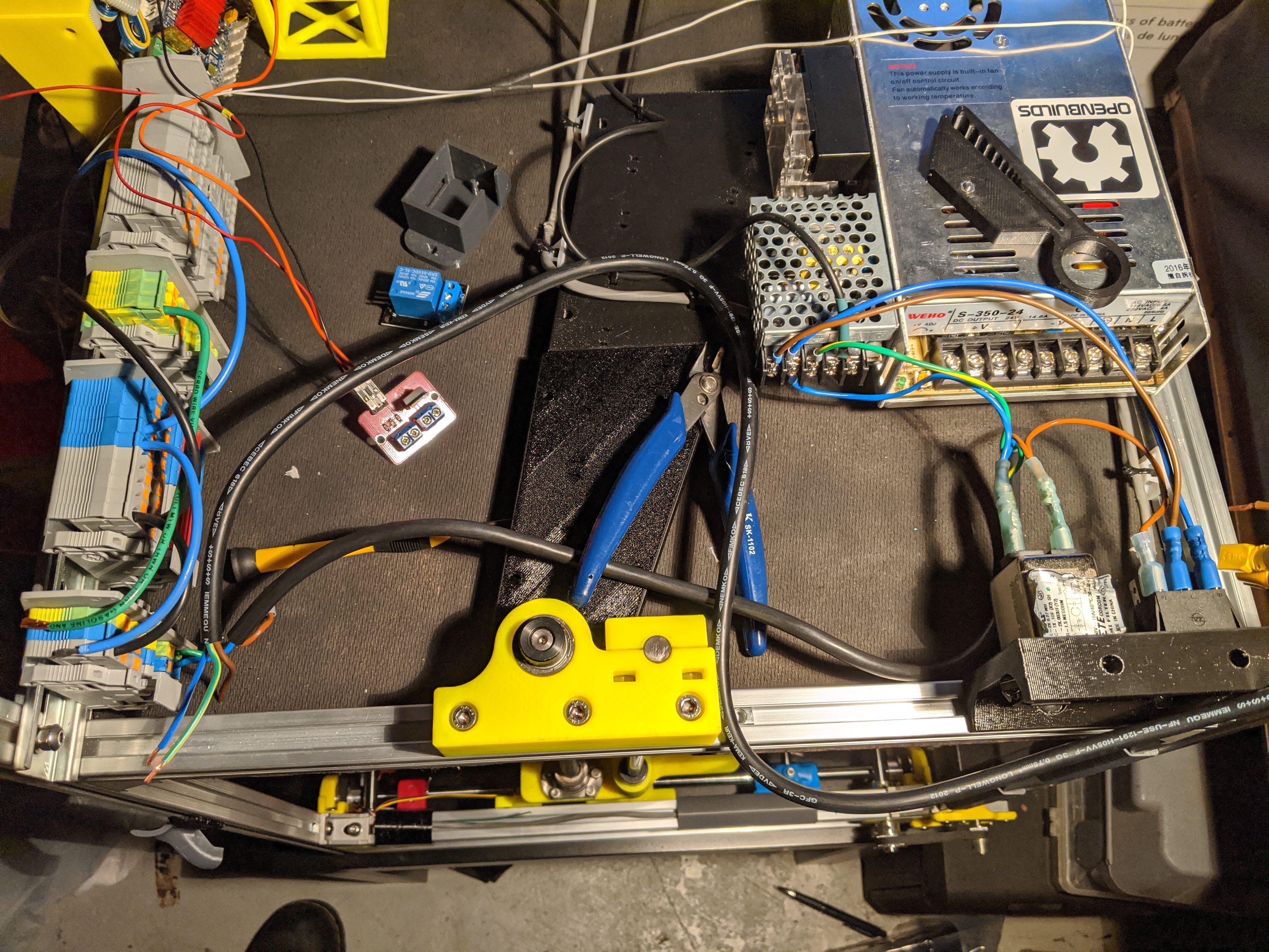
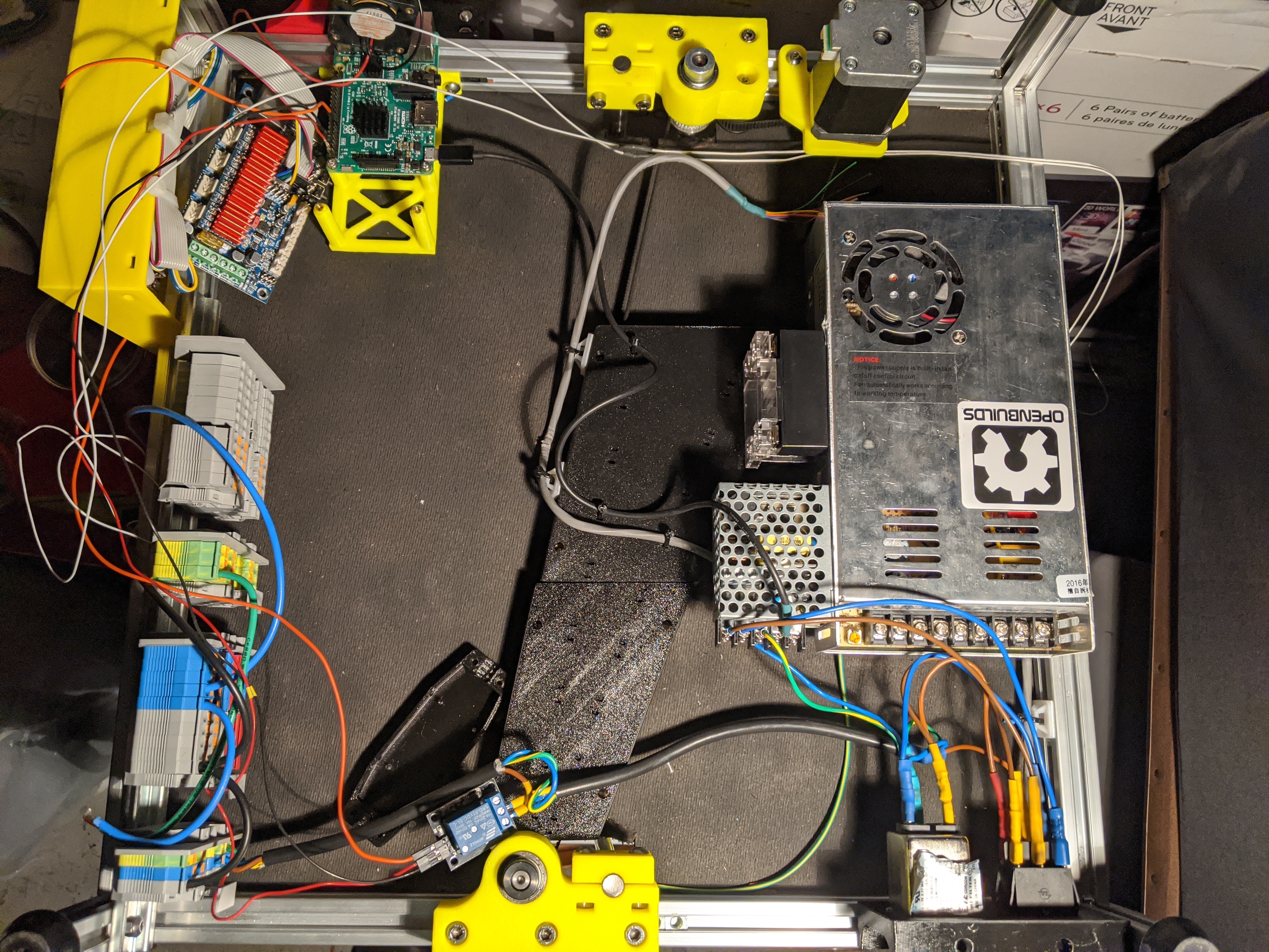
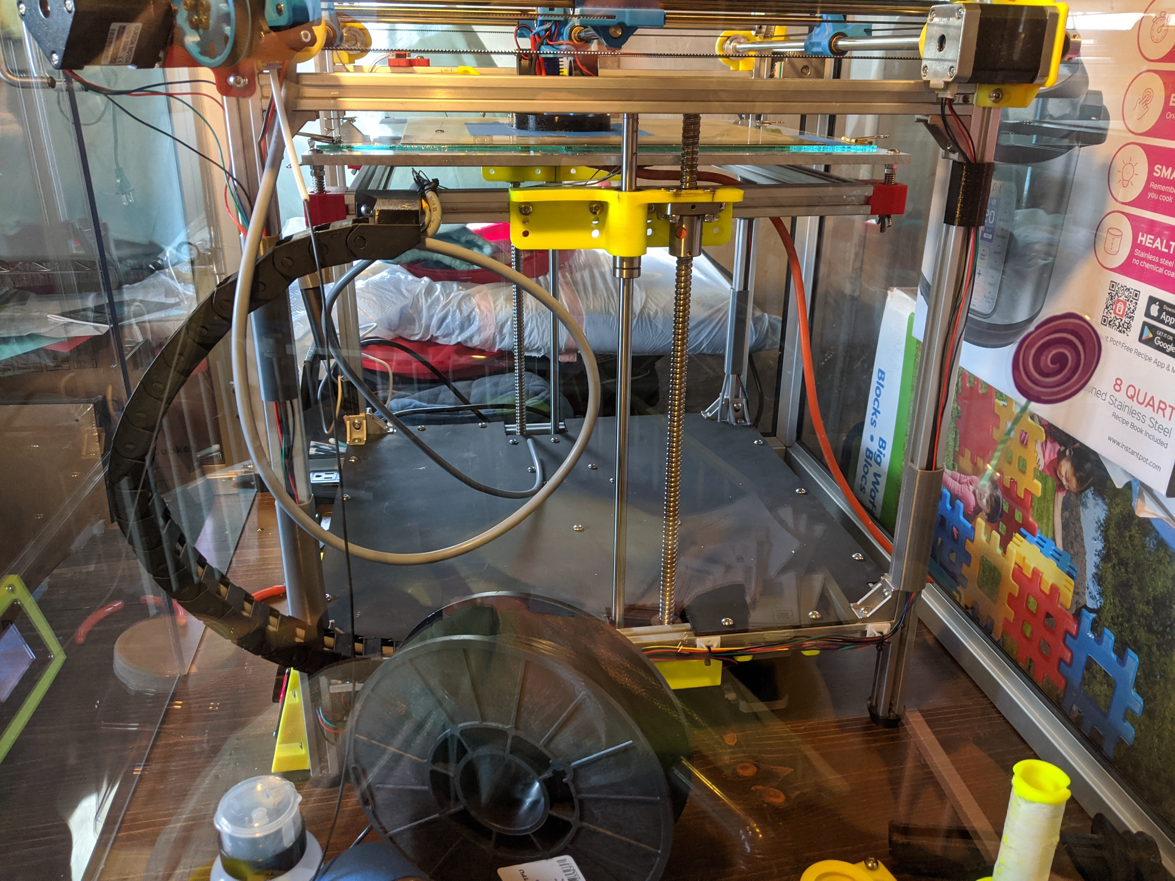
Install plate on the base of the printer to mount electronics
Newly designed cable chain brackets that provide safe cable routing for heat bed to electronics area beneath printer.
2 switch setup, one for 5V PS the other for 24V PS, in process of figuring out how to wire in relay for use with powering printer 24V on/off through octoprint. COVID-19 has really slowed down a few orders from Ali that I placed about a month ago for the 3.3V relays.
I also plan to wire in the cooling fan for the azteeg drivers since it is quite loud and doesn’t need to always run, maybe I can pipe into a thermal trigger on the azteeg board.
I think this covers all the changes I am in the process of SLOWLY implementing. I am house hunting with my wife, so that takes up a massive amount of time, so I have been chipping away at the above stuff for a few months. It is terrible not to have a printer to use for regular stuff that pops up.
Hey Sean,
Might be because I’m at work and a lot of photo sites are blocked, but I’d love to see some pictures of your setup. I too am trying to slowly clean up my Eustathios and make it “neater”. It unfortunately spent some time in a garage while I too was moving in to a new place so it also needs some TLC. Would really enjoy seeing some setup pics to inspire me to organize my rats nest of a printer setup.
Thanks for your work on this carriage, it looks really nice. Would there be anything preventing me from using PETG with this design? I too don’t have an enclosure and can’t print ABS very well. I also really don’t dig the fume smell from it and really only print in PLA and PETG these days.
Hi Ryan,
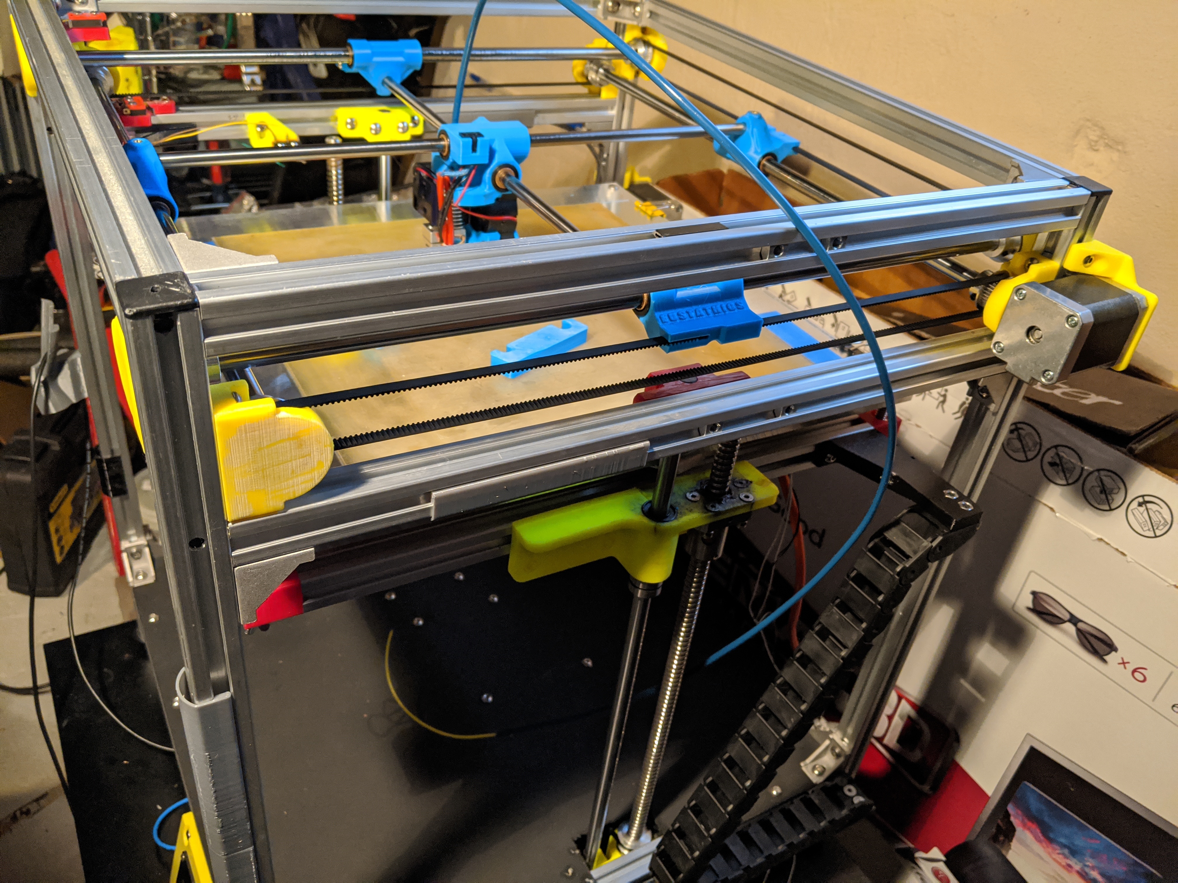
I will try and add a few pictures. I haven’t taken many because it’s still in process and rather ugly, I have a work dungeon (which is basically a corner that is very crowded in my basement).
I have included a partially completed wiring diagram, that has been tested as of this morning to power the system on using octoprint and the GPIO raspberry pi outputs. I have 2 switches on mains, one is 5V and the other is 120V that goes to relay (need switch on in order for automatic activation to function).
I was able to reprint the carriage with modifications that I linked above, the changes worked perfectly. I was able to epoxy the bushings, and now my perpendicularity is much better. I can actually move the carriage by hand now, before there was ~ 1mm misalignment from one end of the rail to the other. I have included images of the originally printed carriage and will add more as it comes together.
Ryan, I forgot to reply to your question about PETG parts. I would highly adviser again PETG for printer parts, it’s too “gummy” and it’s more likely to creep under load.
Not yet, I’ve been stress testing the machine to see if anything comes up. I do need to make some changes in the carriage for the bltouch mount since the holes weren’t big enough for my inserts I had a lot of struggling. I also was trying to finishing the active heating circuit and prints using the raspberry pi GPIO pins.
I’ll try and work on it this weekend, and upload to the GitHub.
@Eclsnowman Do you know how I can upload to Github? I haven’t done it before. I just made an account but it says that the community folder doesn’t permit uploads.


 I can pay if it’s reasonable.