Need to measure Laser

Hi again,

I have replaced the tube on my K40 after an unforunate freezing mishap but thiink the new one from Cloudray may be faulty. I have spoken to someone at Cloudray and sent them a video of the tube working which shows it never gets above 4-6 mA at 99.9% on the digital readout. I have switched back to the M2Nano board from a Monport board as this was suffering the same issue so i thought this a valid experiment.

Cloudray have asked the Following

“What is the voltage of the laser power signal measured on the laser power supply? When using 99.8% power, the measured voltage should be around 4.8V. If the voltage is abnormal, unplug the laser signal plug on the laser power supply, press the LASER button on the laser power supply, and capture the discharge status and current size of the laser tube.”

As i am fairly new to all this, can someone explain where i should be taking these measurements from on the LPS please? I am using this model LPS

Happy to provide any further information required.

thanks

I think they are asking you to measure the IN pin as this controls the power from the panel. Depending on what kind of control panel you have, measure this to the ground when the pot is at max or the digital display is set to 100%.

I think laser signal refers to the L or IN pins. If it’s IN, why are they calling it Laser Signal?? I am guessing they want to measure the laser power without any external control.
The IN is on the second [3-pin] connector from the right.
The L is on the larger 1st connector on the right.

The discharge current is read on your milli-ammeter. I am assuming your machine has a mili-amp meter since you reported the current to them.

This is what they are trying to test.

The IN pin controls power at the machine. It should be near 5V to get full power from the tube.
With the IN pin at 5V pushing the TEST button on the LPS should result in the tube lasing at its max current.
If the IN pin is not a 5V when the panel control is set to full power then something outside the LPS is stopping the IN pin from being 5V and commanding full power. This would suggest the problem is not the tube.

Note: I am not used to seeing the two white wires connected to the left two pins of the 4 pin power connector. Do you know where these go?

Hello All

@donkjr - thanks for the reply , the wires you enquired about appear to go to the internal lights .

i’m getting 4.95v across gnd-IN which should be fine. I’ll give them this info and see what they say.

I,m pretty sure its the tube as its the only thing changed and wont puch throuhg cardboard at 99.9% on the digital and never goes above 5-6 amps on the Ammeter. It is intermittent as to when it fires tbh.

Watch this space!

  1. properly working tube
  2. clean and aligned optics
  3. proper focus

If you have these three. they work.


When you did an alignment, how does the output of the tube, entering m1 look.

I’d suggest you ensure it’s operating in TEM00 mode or resonance.

If it doesn’t produce a proper Gaussian power distribution across the beam, it will never align or be useful.

Good luck

:smile_cat:

@jkwilborn thanks for the input, i have sent my findings back to support to see what they suggest next. A replacement would be ideal or at least a refund.

I have done an alignment to test the tube which may not be optimal but works . I dont want to spend too long on it if the tube is faulty which is what i suspect.with it failing to cut through 1mm cardboard at 100% ( where it used to do this at much lower power with the stock tube) as I have not changed anything but the tube and aligned it to get it to pass through all mirrors cleanly. My main concern was the lack of movement on the Ammeter reading at different power settings.

I am not anything like an expert and know enough to get myself into trouble more often than not, hence my coming here for assistance ( which i appreciate greatly).

Hi all, still trying ti sort this, will update shortly.

thanks

Hi again,

They have agreed to replace the tube and i will get a replacement within a week or so.

When i receive the new tube, is there a “cheap” way to test the power output to ensure it is working correctly ?

I know there are laser power measuring devices but they all seem too expensive or am i looking at the wrong thing ?

thanks

There is no cheap way to measure your tubes output…

Measure the tubes length and use this table to determine what the output and current limits should be. The Chinese seem to enhance these values.

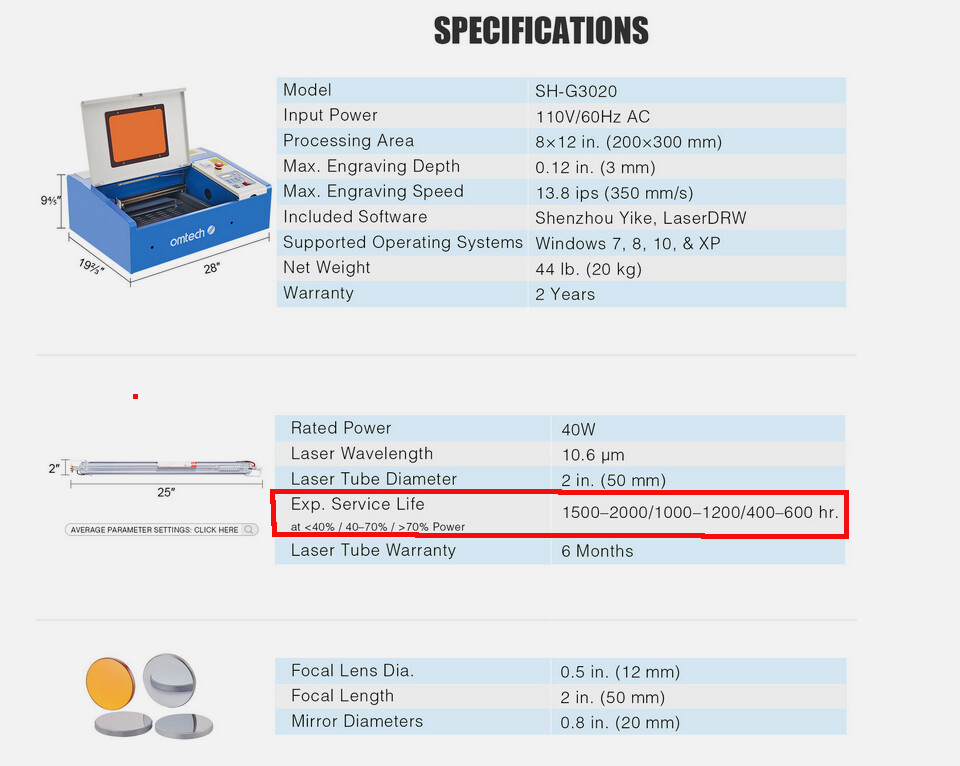
I bought a OMTech 50W… the tube was 880mm in length and measured 43W, which fits well with the tables value. The distance between the mirrors is where the light amplification occurs and where the power is generated. We generally just measure the overall tube length.


I have both a Mahoney meter and a doHICky from Russ Sadler.

Russ has a good video on measuring output wattage … worth watching overall. At about 10:52 minutes in, he starts talking about his lower cost doHICky.

The Mahoney is a commercial meter.

The doHICky requires a comparator and a bit of hardware. Russ sells the bit of hardware and the comparator is available from most of the large outlets… This is the one I have from Amazon, so you can find a suitable one.

Sorry I don’t have his current price for these or if he’s even got them available anymore. If you are interested let me know and I’ll pm you his email so you can easily ask him.


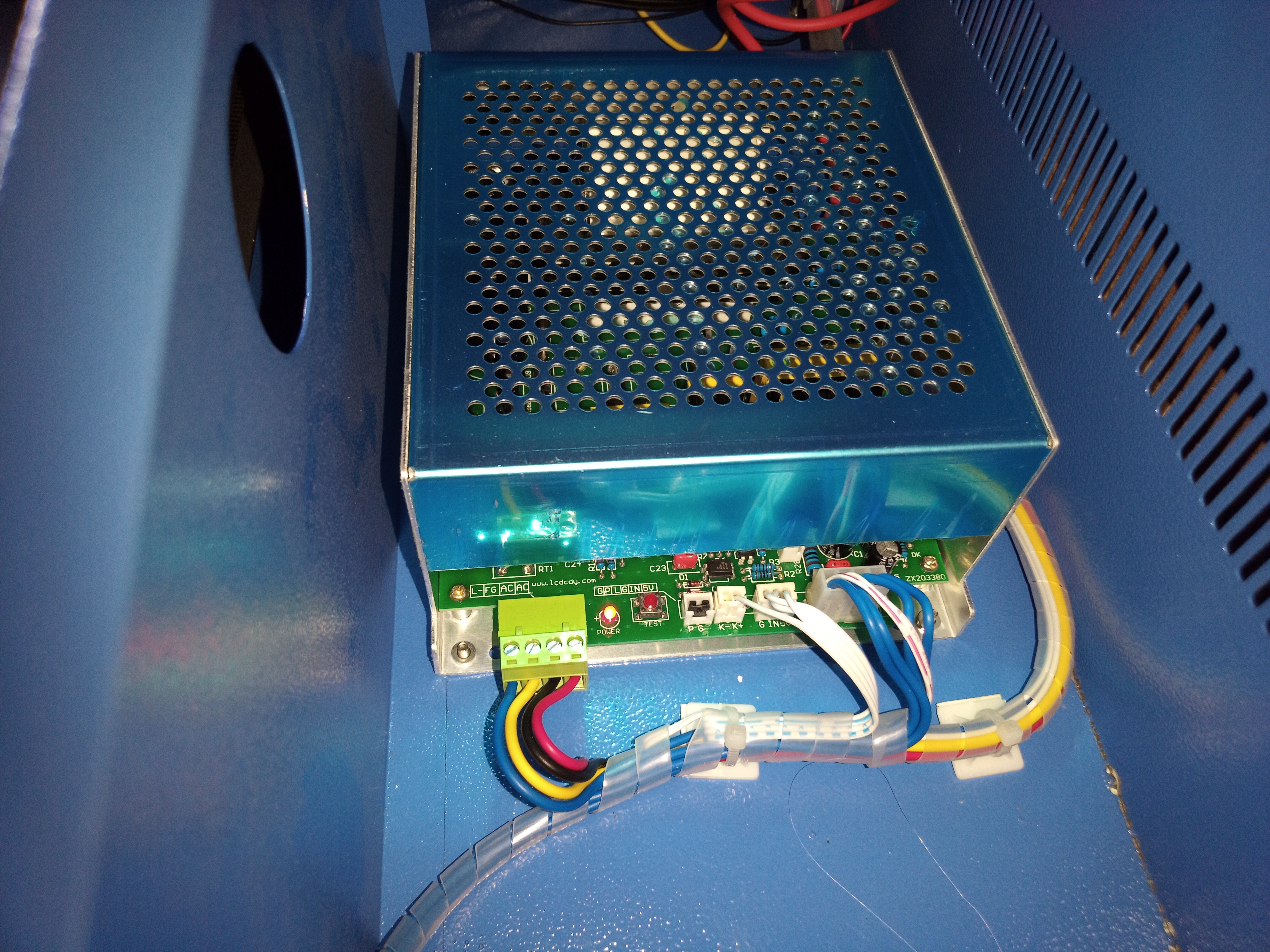
A glass tube will draw as much current as the laser power supply (lps) will supply … that’s the purpose of the IN terminal on an lps.

If your K40 has a pot or current control on the console, it’s manually adjusting the IN voltage so ignore the following as it will lase at the pot setting anytime it lases.


Generally speaking don’t test your tube at 100%, it’s much wiser when setting up new hardware to set it for 50% and double the results. If you lase it at 50% power then there is leeway to avoid too much current. If it measures 8mA at 50% then it’ll be 16mA at 100% supplied by the lps.


If you have a console mounted current control, then the mA meter will read the percentage of power… If you read 3mA@20% power, the rms current read will be 1/5th the actual current … 3mA@20% power has to have 15mA running through it 20% of the time to have a reading of 3mA.


If you have questions, sing out… :wink:

Good luck … have fun

:smile_cat:

Sorry for not replying sooner and thanks for your reply.

I dont really want to invest in anything expensive to measure it, as ths is still very much at hobby stage and i may rarely need it again. Guess i was hoping there was some sort of hack available for measuring approx values.

Still waiting for the tube to be delivered so fingers crossed. Will see how it goes and come back if problematic and seek inspiration from here.

cheers all.

@jkwilborn what would you guess for a 40W new fully validated (class A?) tube would cut 5mm baltic birch plywood at? One pass: 15mm/s @ 75% power? You know, given proper mirror alignment, level bed, clean lens and focused properly to the surface of the plywood.

My 6 year old stock tube used to do 3mm BB ply ~12mm/s @ 60%.

I cut 5mm sub flooring, which is a plywood, I believe around 7mm/s@70%, this is from memory…

Never tried any kind birch wood, plywood or other.

:smile_cat:

40W CO2 laser? OP was asking for some way to ‘measure’ laser power but doesn’t want to spend $250 for a tool to do it therefore I was giving an example of what has been done with new//original ~40W tube in my K40. Relevant since the OP is getting a 40W tube.

A 40W tube is around 850mm in length… I doubt his K40 case is even that wide. A 30W tube is around 700mm…

Most of the K40’s I see have a 720mm length tube, so it’s likely closer to a 30W … Also note the difference in current limit.

This previous video by Russ on power meters explains how they work and shows a Mahoney and a doHICKy that Russ has created. I have both, the is a commercial meter and you can pick up the parts for his doHICKy from him and the thermocouple/meter from Amazon.

I think you need to go to about 29 minutes in to see the doHICKy. Must have typo’d the first post…

Both meters are great… The doHICKy might be a bit lower cost. You can check out the Mahoney. The doHICKy is 1 x dohicky (less £5 postage) £25 plus the thermocouple at about $20 US.

The doHICKy is lower cost.

:smile_cat:

1 Like

ha, just roughly measured the length of my old tube and sure enough, ~700mm.
I want my money back! LOL

And cool doHICkey Russ made and tested.

1 Like

Are you using a maximum current setting of above the 30W 15mA limit?

I thought your original tube has been operating for 6 years?

:smile_cat:

I’ve not yet adjusted the LPS to lower the max power, i’ve only adjusted the IN voltage setting to limit avg output to 18mA.

yes, it still is operating and is a rather old tube. I can see how “old” in the statement could be taken as old=previous as opposed to old=aged. :slight_smile:

1 Like

As we’ve discussed before, anytime it lases, it will lase at the IN current setting.

The current control is the manual pot. These are setup for power/time relationship, same kind of control that’s used with a ssl.

So if it’s set for 18mA, it doesn’t matter if you’re only running at 10%, when it lases during that 10% time period, it’s drawing 18mA.

Gives us some idea how tough these things really are.

You can see these K40’s don’t have a good tube life in any case. It’s arguable but RECI states 10k hours on a tube.

It’s easy to confirm with your own mA meter. If you read 3.6mA@20%, this is 20% of 18mA or 3.6mA. Since the meter isn’t continuous, it is controlled, although indirectly, by the L input or pwm signal and it will read rms. Same as if you’re reading a 5V pwm signal where the signal is 0 to 5V but at 50% pwm, it will read 2.5V not 5V.

Many of these variants are starting to wire them up using the IN for the pwm and L or P for the laser enable… This would, at least allow the software to limit the current draw.


I was reading and understanding you have used that machine for 6 years with the same tube, so I was wondering what old meant in this context.

:smile_cat:

I though I’d heard that age is just as much an issue as lasing so my 6 year old does not have lots of hours, just lots of years. But I’ve never run it over 25C and I have run sessions for a few hours at a time.

I’d suggest you drop it to match the chart value of 15mA… IMHO…

Good luck

:smile_cat:

The analogy with PWM signals and voltage readings isn’t entirely applicable to current measurements. While it’s true that PWM signals modulate voltage, the behavior of current in such circuits can be more complex. In some cases, PWM signals may not directly control current flow, especially if additional circuitry is involved.

Regarding the suggestion to wire variants using IN for PWM and L or P for laser enable, this could work in certain setups. However, it’s crucial to ensure that the software controlling these signals is properly calibrated and synchronized with the hardware. Otherwise, it could lead to inaccurate current regulation or even damage to the equipment.