Hi. I have a gcode .nc file that I used to mill letters into wood. I now want to 3D print those letters (the material the tool path removed) so I can use it as inlay in the wood.
Cura fails to load the .nc file and I’m trying hard to not have to draw the letters in a new STL file that I could then convert to gcode and print.
I’m not aware of any (software) tool that can go from Gcode back to solid shapes, which is what you need to do.
I suspect that laboriously drawing it out to get a solid .stl is your best solution. Sorry.
An alternative would be to use the existing code to carve the letters in some nice heavy wood and use that as a mould to cast the letters in. You could even do that and then scan the resulting casting to get the solid model that your slicer needs.
the .nc was created with a very old version of MC. I do now have the file exported to a .DXF and was able to open it in FreeCAD (v0.21.1). My problem is that my tool paths (letters/numbers) are just lines and have no weight. I’m trying to convert a 2-D tool path to 3D objects.
Yes, manually creating the STL might be my option but it’s frustrating
when I already have the geometry paths.
A toolpath isn’t really a geometry. The DXF at least gives you “wires” from which you can create an object. I’ll ignore your frustration and try to help you solve the problem you have. There are multiple possibilities here. I recognize that they might require more learning than you were looking for…
I think in FreeCAD you would take the wires and do a 2-D offset in the Part workbench, then extrude with a draft angle. If you don’t yet know how to do that, I think that MangoJellySolutions on YouTube has some relevant video tutorials. I think that https://www.youtube.com/watch?v=-539fgU50Bw shows the 2-D offset tool and its options. The FreeCAD Forum is another place to turn for help there, too.
Knowing that you have a DXF, if you are comfortable with modeling from code, I’d also consider OpenSCAD for this. I’d try to import the DXF into OpenSCAD and create the minkowski sum of the imported path and the shape the tool bit cuts: for a v-carve bit, that would be a cone; for a flat end mill, a cylinder; and for a round nose mill, the union of a cylinder and a sphere.
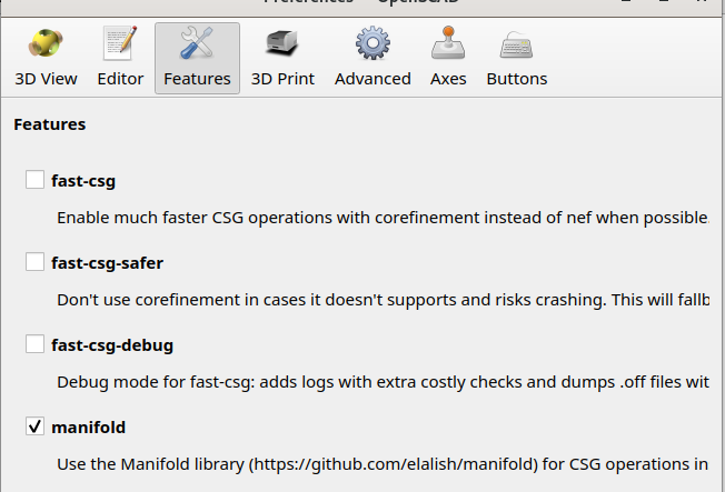
Although minkowski has been a very slow operation in OpenSCAD in the past, recent development releases of OpenSCAD do it quite quickly if you enable the Manifold kernel in the settings. Edit → Preferences, then:
I was able to come up with (all be it ‘hacky’) solution:
While viewing the .dxf in FreeCat, take a screenshot of the letters (not selected)
Paste the screenshot into GIMP (image editor)
Select the text from the image and pad selection
Select the new padded letters and add a new path to the selection
Select the path and export to .SVG
Import into Thingiverse
Skew to the right proportions as the milled text.
Export to .STL
Open in Cura and export to .gcode
Print. I found that using brims caused the letters to be too large so in thingiverse I added a support bar to the top and bottom of the letters that was .7mm thick. This could easily be removed post print and kept the letters held down when printing.