I bought a CNC from a guy who builds it and he used this specific board for my CNC machine. What I don’t understand is that he added a Variable Frequency Controller to control the spindle. I have to switch it on here and also set the speed after dividing the required speed by 75.
From videos I have watched, it seems that there is no need for this frequency controller and that the spindle is switched on and off in the GCODE.
Another builder told me that the frequency controller is not necessary as the board can do that by itself. I don’t want to switch the spindle on and off on the frequency controller. This must be done by the gcode.
He soldered all the wiring onto the back of the board and didn’t use any of the sockets for it.
Can you please confirm that the board can do this and that no Frequency Controller is required?
I want him to redo the wiring so that I don’t need the Frequency Controller.
I’d suggest not to buy this type of hack. Don’t mean to be derogatory, but when you have connectors, do it right, not a hack job to get it running.
It shows little insight into maintenance or debugging of hardware problems.
It’s prone to inducing wiring errors.
If the board fails, it will be a can of worms so to speak.
The DLC32 puts out a spindle control voltage or pwm output that is for spindle speed control. I don’t know what this output is, offhand, but it’s schematic is on github and I think it just completes the ground when it’s on.
I have no idea of the kind of spindle you have or it’s requirements, without that I can’t offer much.
I had a CNC3018 that I upgraded to a 500mW spindle… That required a control voltage encompassing 0 to 10V. I picked up a pwm → analog voltage board which sort of worked. It being a 12V system the converter board could never quite reach 10V so no 100% speed. It does work fine with a 24V supply but added complexity.
You need to supply some information of what you are driving… not all spindle or spindle control signals are the same… but are similar.
What is the manual adjustment, an external box or ?
As @jkwilborn suggests we need to know what kind of spindle motor you are using.
If it is not a DC motor you will need a VFD and that may need manual speed adjustment.
The Frequency controller is controlling the speed of the spindle. Whatever the speed must be, must be divided by 75 and that number is set on the Frequency Controller by turning a knob.
From the manual below:
If you want to control the motor speed this vfd can be controlled by a 0-10V analog signal.
In this config. you will need to convert whatever control signal you decide to use on the DLC32 to an analog 0-10V signal and then program the VFD to accept that signal.
If you just want to turn the motor on off at a fixed speed, you can use relay interfaces.
I suspect you can learn more by doing a search on which configuration you want to pursue.
Hi, I have a couple of the DLC32 v2 boards, unfortunately. The old USB chip it uses is so prone to disturbances that there is no way to reliably drive a motor through it, it messes up the connection, and freezes. The only way I got them to work was by completely bypassing the motor power through the board, and only using a octocoupled switch as on/off for the motor. Will need to make a logic converter to drive the 0-10v range for a VDF at some point.
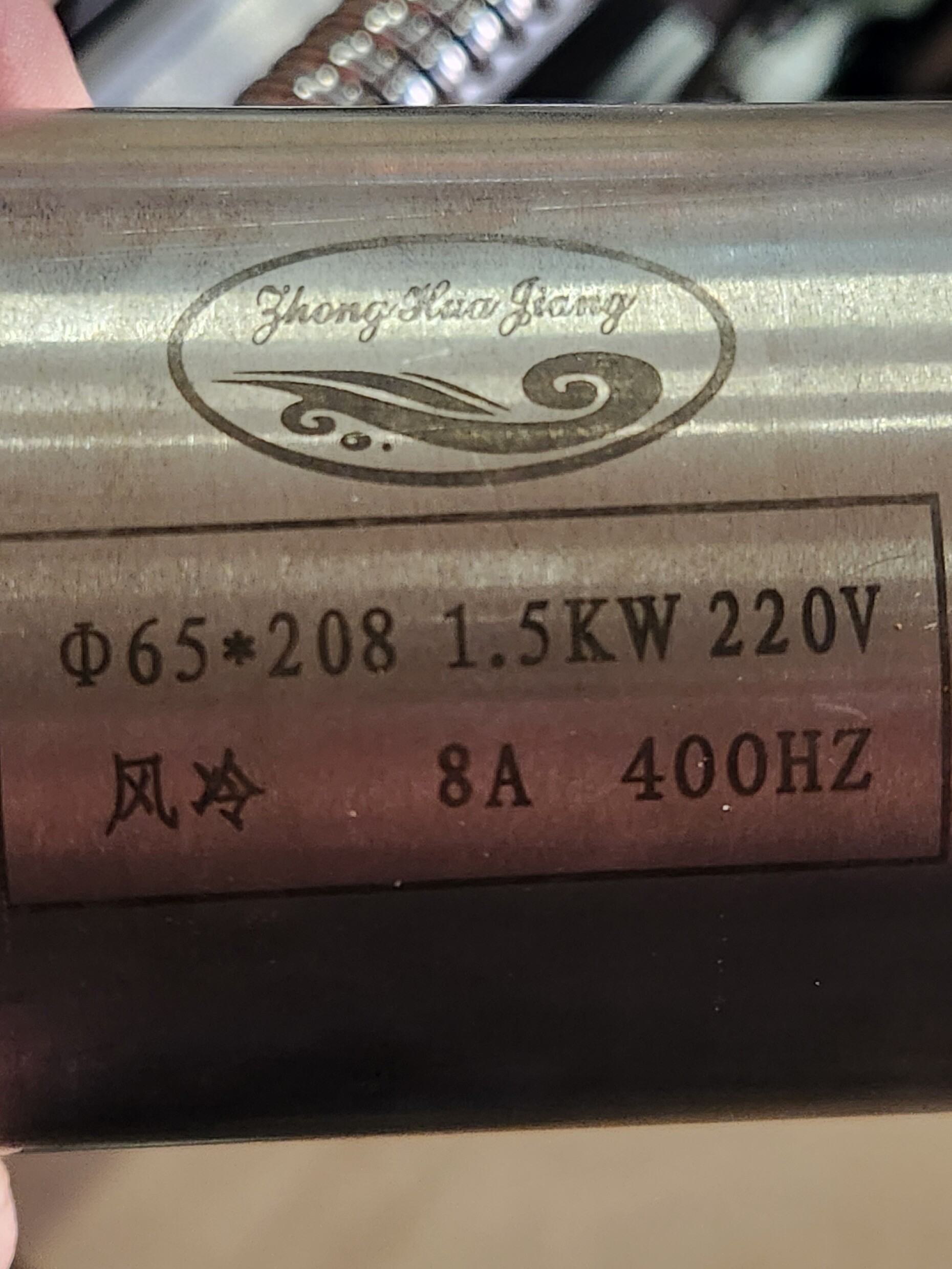
And yes, if you use a 1.5Kw 3-phase motor, you do need VDF driver for it.
Another thing that might be good to know about this board is that there seems to be some math issue in the Spindle speed setting, so it seems that the max should be set to S1000. Otherwise it divides the speed calculation wrong, and spits out unexpected speeds
Hello professor, please please,
I have a problem with the MKS DLC32 card, which is that I cannot reach high speeds with it. Is there a software solution or perhaps an electronic solution, such as adding an electronic element or card to amplify or accelerate the signal? Thank you.
Please respect the request and start a new thread. Describe your problem in enough detail that people can actually help you.
It looks like it might be worth reading this section from our FAQ on how to get good help here on Maker Forums — and really, anywhere else on the internet, or even off the internet!