In order to have the Offline ability to control my CNC I decided to replace my Arduino Uno controller with the MKS DL32 + TS24. Populated the GBRL settings from my “working” Arduino into the MKS and got the movement working on all the 3 axis.
However, for some strange reason I am encountering issues with incorrect steps/mm and homing not working as they I did with the Arduino Uno.
X-Y are 5mm pitch SFU1605 ball screws and Z is 4mm pitch SFU1205
The DM542T drivers are set to 10 microsteps and used the below formula
(200 x 10)/5 = 400 steps/mm (x-y axis)
(200 x 10)/4 = 500 steps/mm (z-axis)
For some reason the MKS controller is not producing the desired travel movements and secondly another issue which I believe stems from the above. During Homing, the bounce back setting is not being processed and the controller goes into Alarm mode when the first limit switch is triggers.
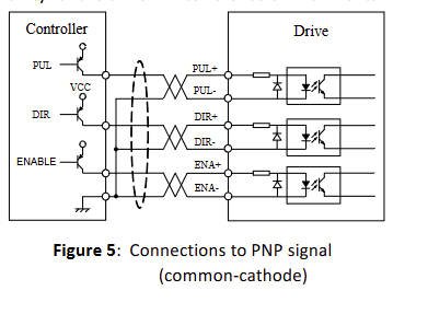
I will be grateful if someone can shed some light on why the Arduino GBRL settings are not working when using external motor drivers with MKS DLC32. Are there any changes I need to make on the DIP switches in order to get the controller to work with external drivers?
The issue I am experiencing is as shown below with the discrepance is about 3.4mm less and I tried changing the bold values below to compensate for the difference but the difference continues to compound.
Desired Actual Discrepance
10mm 6.6mm 3.4mm
20mm 16.6mm 3.4mm
30mm 26.6mm 3.4mm
40mm 46.4mm 3.6mm
100mm 96.5mm 3.5mm
What could be causing the above issue??
Below is the GBRL settings:
$0=10 (Step pulse time, microseconds)
$1=25 (Step idle delay, milliseconds)
$2=0 (Step pulse invert, mask)
$3=1 (Step direction invert, mask)
$4=0 (Invert step enable pin, boolean)
$5=1 (Invert limit pins, boolean)
$6=0 (Invert probe pin, boolean)
$10=1 (Status report options, mask)
$11=0.010 (Junction deviation, millimeters)
$12=0.002 (Arc tolerance, millimeters)
$13=0 (Report in inches, boolean)
$20=1 (Soft limits enable, boolean)
$21=1 (Hard limits enable, boolean)
$22=1 (Homing cycle enable, boolean)
$23=1 (Homing direction invert, mask)
$24=25.000 (Homing locate feed rate, mm/min)
$25=500.000 (Homing search seek rate, mm/min)
$26=250 (Homing switch debounce delay, milliseconds)
$27=4.000 (Homing switch pull-off distance, millimeters)
$30=1000 (Maximum spindle speed, RPM)
$31=0 (Minimum spindle speed, RPM)
$32=0 (Laser-mode enable, boolean)
$100=400.000 (X-axis travel resolution, step/mm)
$101=400.000 (Y-axis travel resolution, step/mm)
$102=500.000 (Z-axis travel resolution, step/mm)
$110=1000.000 (X-axis maximum rate, mm/min)
$111=1000.000 (Y-axis maximum rate, mm/min)
$112=500.000 (Z-axis maximum rate, mm/min)
$120=80.000 (X-axis acceleration, mm/sec^2)
$121=80.000 (Y-axis acceleration, mm/sec^2)
$122=10.000 (Z-axis acceleration, mm/sec^2)
$130=440.000 (X-axis maximum travel, millimeters)
$131=500.000 (Y-axis maximum travel, millimeters)
$132=50.000 (Z-axis maximum travel, millimeters)
