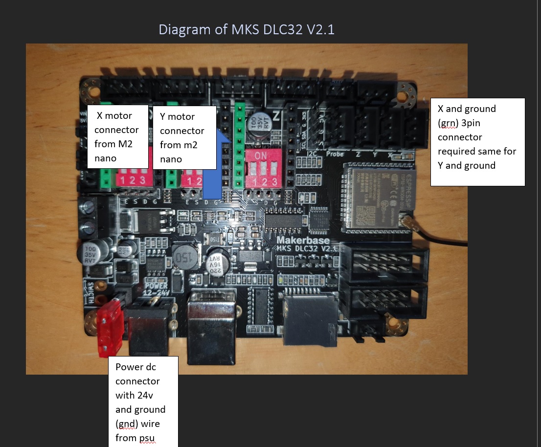
I’m looking for some assistance as I have just bought a MKS dlc32 2,1 board for my K40 as it would be nice to wifi and to be able to use lightburn directly instead of going via meek40t, now looking at some forums and you videos I have managed to work out where some of the wires go, see attached picture
and that I will need to order 2 x 3 pin pcb connectors for the limit switches and a dc connector for the 24v power required
I want to check the following before I start the work.
Does anything else need to be attached to the board for the K40 to work?
Since I cannot get to motors to see what they are with out taking the machine further a part (I’d rather not), is it ok to move the jumper switch until I find the correct one with out damaging the motors?
What setting will need changing in lightburn?
How do I limit the max power so I do not damage the CO2 tube in lightburn
5: What will not work after the change?
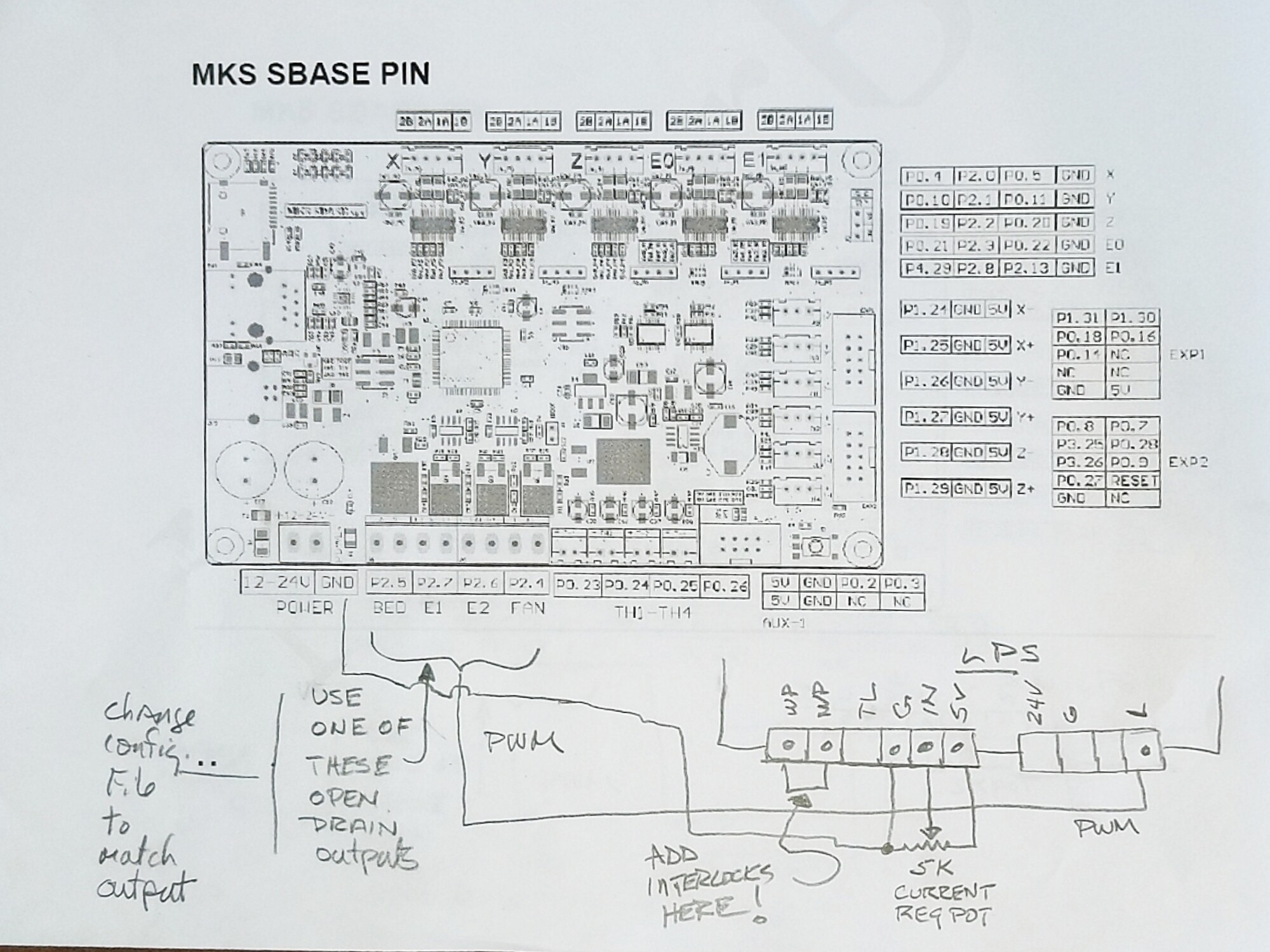
Yes, you need to connect up your laser PWM control. It is common to leave the POT connected to the LPS( 5V/IN/Gnd) and use that to set your maximum avg current output(~18mA) and then you use one of the FET connections on the board to pull the LPS-L signal low for PWM control.
Stock motors are 9deg motors so 400 steps/rotation. As for the switches on the board, those set the micro-step setting and you can use 1/16th or 1/32 and after you set the jumper, install the motor driver boards(tmc2209 can be a good choice) you have to setup your firmware config’s “Steps/mm”
so that when you command it to move 100mm it moves the motor enough steps to truly get 100mm of movement.
[quote]What setting will need changing in lightburn?
[/quote]
LightBurn does not care about your microsteps, it will send GCode which tells the firmware to move 100mm in X and 50mm in Y and expect the firmware to tell the motors to do that accurately.
You don’t, you set the POT which puts a voltage into the LPS-IN signal and intern sets the max avg power the laser will output. In the firmware you set it to output 100% PWM as max and LightBurn is non the wise about what’s going on at the laser except to command it to set the lasing to some percentage of power which you define in your layer settings.
This is considered and upgrade and what won’t work is any application which expects to be controlling an M2Nano board because it now is not and M2Nano.
What firmware will you be installing on this controller board?
This is a conversion I helped with but is not the same board. The implementation should be similar.
Perhaps you can use this as a reference to choose the equivalent connections on this alternate board.
I thought the board has a separate laser enable and pwm output… Am I mistaken?
Just looked at the pdf… I didn’t see a laser enable line…
And I have one of these boards…
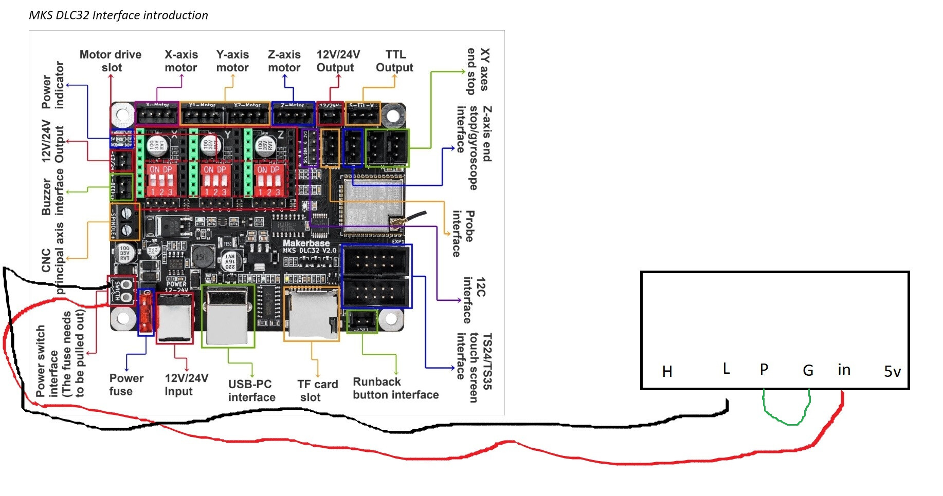
The L input is laser enable, but most also have an H input, which is enabled high, so you wouldn’t need to invert the output signal… just wire it to the H input instead …
yup, it seems to work and it is how 100% of the K40 machines come from the factory. They either have a POT across 5v/IN/Gnd or they have a digital POT doing the same thing. PWM is always into the LPS-L input.
But the Ruida machines are another story and as you mentioned, LPS-L is used as Laser-Enable and PWM is driven into the LPS-IN signal.
I do like your method of limiting max current output via the onboard LPS output POT but as the tube ages it can be a bit tougher to up the power a bit so that a 70% power cut is the same as new and as aged. With the front panel POT we can easily adjust the avg output power through the tube upward so that numbers we are familiar with, on materials we are familiar with, cut the same on day one and day 1000.
I would still like to get to the bottom of these differences to see where there might be signs of vastly better or worst results.
I will be using Makerbase own firmware which works with the ts24 touch screen. This is now working with the motors on my K40. just need to resolve why the x y axis is when moving is bouncing i.e moves the returns to the original position. This happens in Lightburn or Laser Grbl
I’ve run my machine hard for over a year, I check it’s output at least bi-weekly… By hard, I mean 25C setting on the chiller, engraving or cutting at 80 to 90%. Never saw a drop in any of the obvious measurements… One morning it wasn’t performing well…
Same hv, mA readings at the same percentage setting … the Mahoney says I’ve lost over 15% power since last measurement.
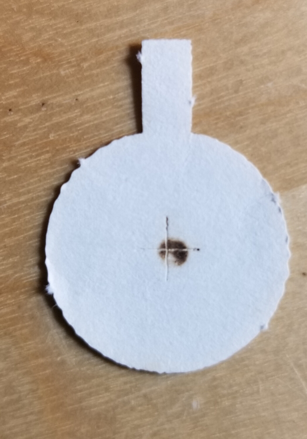
The tube appears to be moving out of TEM0, as you can see from this spot taken the day I noticed a problem at m1. This took less than a week to go from great to poor. In actuality, operating the machine, it seemed to work fine the day before. The last time I did a resonance/power test was the previous week and it was fine.
One thing I noticed is the beam is off center … ? Might be why you notice something isn’t right when it doesn’t work evenly across your work area.
Have a new tube here from cloudray, but I’m going to beat this tube up pretty well before I change it out…
Any suggestions on types of ‘abuse’ I can try …? It’s had it anyway… might as well see what it can do with the dying carcass … First time I’ve had a change to ‘abuse’ one
First time I’ve had this happen to me, seen it a bunch of times… It’s isn’t the ‘doughnut’ type pattern, that seems most common …
There isn’t an attempt to hi-jack the thread here and @mcdanlj or one of the other moderators can move it if they feel it would be better for the site, damn ‘pot’ issue
That is viciously hard… discussions on operating range I’ve read say to shut the machine down at 25C so starting the chiller at 25C means the tube is running hotter than that.
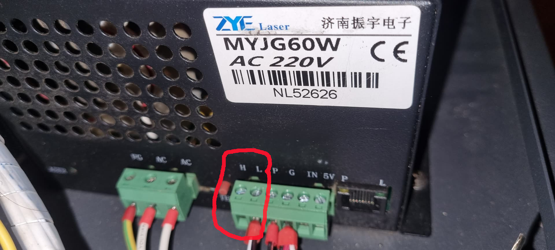
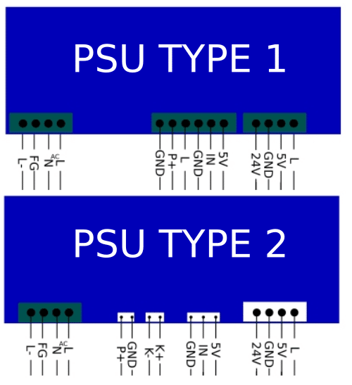
So just need to confirm something and we are hopefully up and running. So from what I have understood for the laser to fire we need the L- and the IN from the psu type 2 wires from the psu going to the motherboard spindle and L- on the spindle negative and IN on the positive, is this correct?
The reason for asking is I may have accidently killed my tube