I have wanted a rotary broach for a few years. (A rotary broach is a tool for drilling non-round holes, such as hex or square holes.) I looked at a lot of plans online. I spent hours reading forum posts. My youtube viewing history for rotary broaches reaches back to 2018! A couple months ago, I finally bought the Hemingway rotary broach kit.
It’s not really that expensive as things go. Shipping to the US is not horribly expensive, but I had even cheaper shipping because some of my colleagues working in one of our UK offices were coming to the US and had some room to bring me the kit, so I just had to pay domestic shipping.
It was a good idea. I’m glad I got it, and would make the same choice again. And this picture of my new rotary broach isn’t the Hemingway design, even though it is superficially similar on the outside…
The Kit
Hemingway shipped a full set of detail drawings, quite detailed instructions, and all the hardware and stock necessary — as long as you don’t make any mistakes. They included enough 8mm “silver steel” drill rod for about three actual broaches as well. (For those inside the US, 8mm drill rod is harder to find than imperial sizes, so an option to ship more drill rod would have been convenient.)
The instructions, though long, were unclear on a few points. When I asked one question (how to harden the silver steel) on a weekend, I got a very fast response from Hemingway that it was a water-quenched steel. I would expect that they would be just as quick to answer any other question.
There were a few problems:
- The instructions, though generally very clear, have a few places that they aren’t clear. In particular, I found a step for measuring the spindle that made no sense to me.
- The instructions go into great detail about how to deal with not having tilt on the dividing head, and not having angle blocks or sine plate, not mentioning the obvious, cheap, simple solutions. My set of angle blocks was not expensive and made things so much easier.
- Boring 8mm to a 20mm depth to a square end precisely is actually tricky. A lot of boring bars just don’t go that narrow. And getting that fit perfect is hard. It’s also important.
- The instructions suggest precision in several cases where precision is completely useless, and don’t mention precision in a few places where it is important.
- The drawings (dimensioned in both metric and imperial) don’t indicate tolerances anywhere.
I ended up modeling it in FreeCAD to make sure I understood how the parts fit together, and that really helped me understand how the instructions work. Electrons are cheaper than steel.
I made a couple mistakes that were all my own fault as I insisted on working in metric on my imperial lathe without DROs. I made the spindle bore too loose a fit, so that the drill rod rattled in it. In boring out the body that the spindle runs in, I bored one section about .001" too wide, so that the larger radial bearing rattled. I shimmed the bearing with shim stock, but that wasn’t a good option for the spindle bore.
I thought of remaking at least the spindle and maybe the body, but something bothered me. The design includes axial preload on a radial bearing. It has a nut that bears on the outer race of a radial bearing, and then the inner race of that same radial bearing bears on the spindle, which then bears on a thrust bearing. (A second radial bearing is in the tail.) I found that when I tightened the nut as instructed, the radial bearing turned stiffly. This would probably be fine in use because the pressure of using the broach would axially unload the radial bearing, but I didn’t like it anyway.
It’s definitely possible to make this design work, and a few folks with real skills (unlike me) have done this, including Stefan Gotteswinter, Randy Richard, and Inheritance Machining, with their own variations on the design.
Glutton for punishment that I am, I didn’t just grab some more 12L14 or 1144 from the stock pile and use what I had learned to remake one or two parts, more quickly and higher quality.
I Did It My Way
I used what I had learned and started over, mostly from scratch.
- I ordered some 4140 steel after seeing how beautiful the similar Cr42 steel that Stefan Gotteswinter looked. I have never used it before, so this seemed like a great opportunity to expand my repertoire.
- I ordered a set of metric reamers by 0.5mm and a set of metric drills by 0.1mm. I also ground a flat-bottom 9/32" drill (I have several spares) as an undersize drill to get a flat-bottom hole before drilling 7.9mm and boring 8mm. I also ordered a set of metric counterbores instead of continuing to bore with end mills.
- I opened up a fresh document in FreeCAD and made a different design from scratch, and made it parametric and driven from a configuration table so that it can be configured for different lengths and diameters of broaches, using a different bearing layout that simplified the body design, and in which there is no axial preload through a radial bearing.
In my design, I followed Stefan Gotteswinter’s example of using a separate shaft and using retaining compound to lock it to the back collar. The shaft was a dead 3/8" endmill with the flutes chopped off with a dremel. I used a different bearing arrangement, with an F5-12M thrust bearing behind the spindle, and two identical radial bearings around the body of the spindle. I designed a bushing/sleeve so that the nut on the front bears on the forward radial bearing’s outer race, which bears on the sleeve, which bears on the rear radial bearing’s outer race, which bears on the body that holds the nut, so that the whole thing is quite rigid. The only axial load on the radial bearing is when actually removing the broach from the work, which is not a significant load.
I learned first-hand that 4140 is different from free-machining steel. When cutting it with inserts intended for ferrous materials, it has a mirror finish, but when cutting it with sharp ground inserts meant for aluminum, it has a satin finish. This is definitely different from free-machining steel for which the ground inserts usually leave a beautiful finish. It also seems to work harden easily.
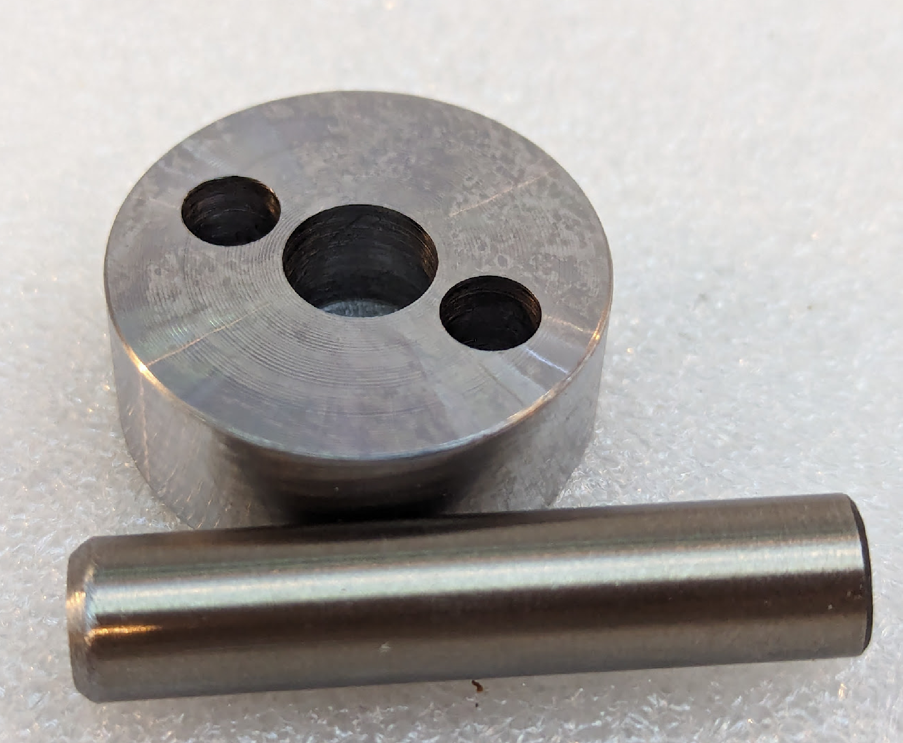
One of the first pieces I made was the shoulder for the shaft. I made that three times for my new design. The first time, I discovered that my old (cheap) set of metric drills, while it was fine for aluminum and mild steel, was not meant for 4140. The hole started feeling weird, and I pulled the drill out and it had a 5° or so bend in it, and the hole was shot. The second time, I was working late and night and cut a tab instead of a slot. That didn’t really matter; I could have compensated later (if I remembered), but I was annoyed with myself and determined to make it to plan. Third time was the charm.
While boring the body, I broke a boring bar almost instantaneously when chatter developed, and when I thought I could fix up the chowdered surface by very careful use of another boring bar, I instead learned again just how easy it is to snap a boring bar. At least now I have some extra screws for carbide inserts for when I drop a screw in the chip tray some day…
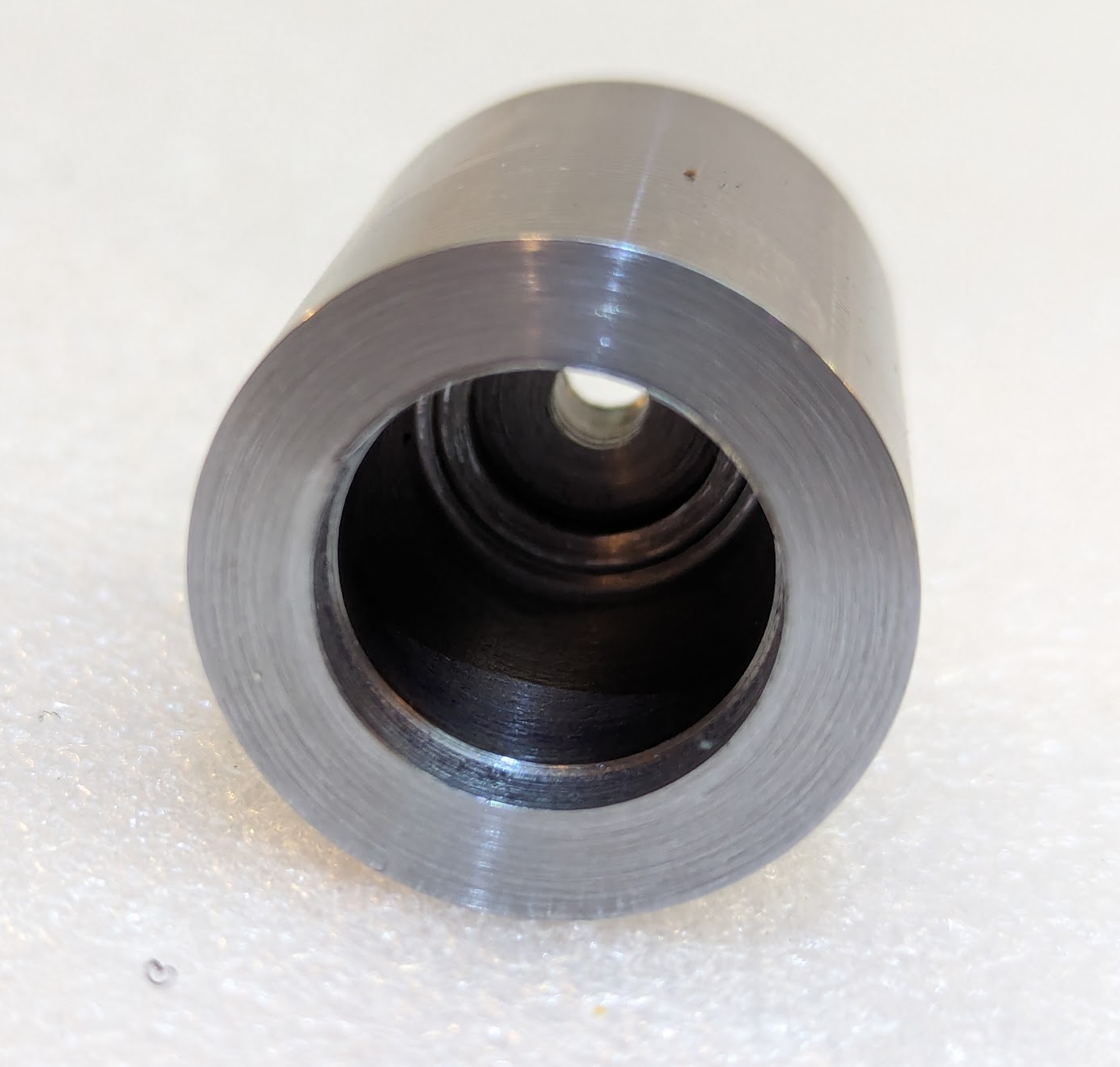
However, I got the sleeve so perfect on the first try that it was a perfect sliding fit in the body, and the body boring job was so good that there is no radial bearing play, yet I can tap the body face down to slide the bearings out. Could not be a better fit! (I made a design error and made the bore for the thrust bearing too wide, but fortunately I also made it too shallow, so I was able to rescue that with a 12mm endmill instead of starting over.) And the spindle bore was a piston fit for the drill rod for the actual broaches (the only remaining part I was using from the Hemingway kit).
I made a few (mostly cosmetic and temporary) mistakes as I worked, but I ended up with a broach holder in which the only appreciable play is between the balls and the races in the radial bearings.
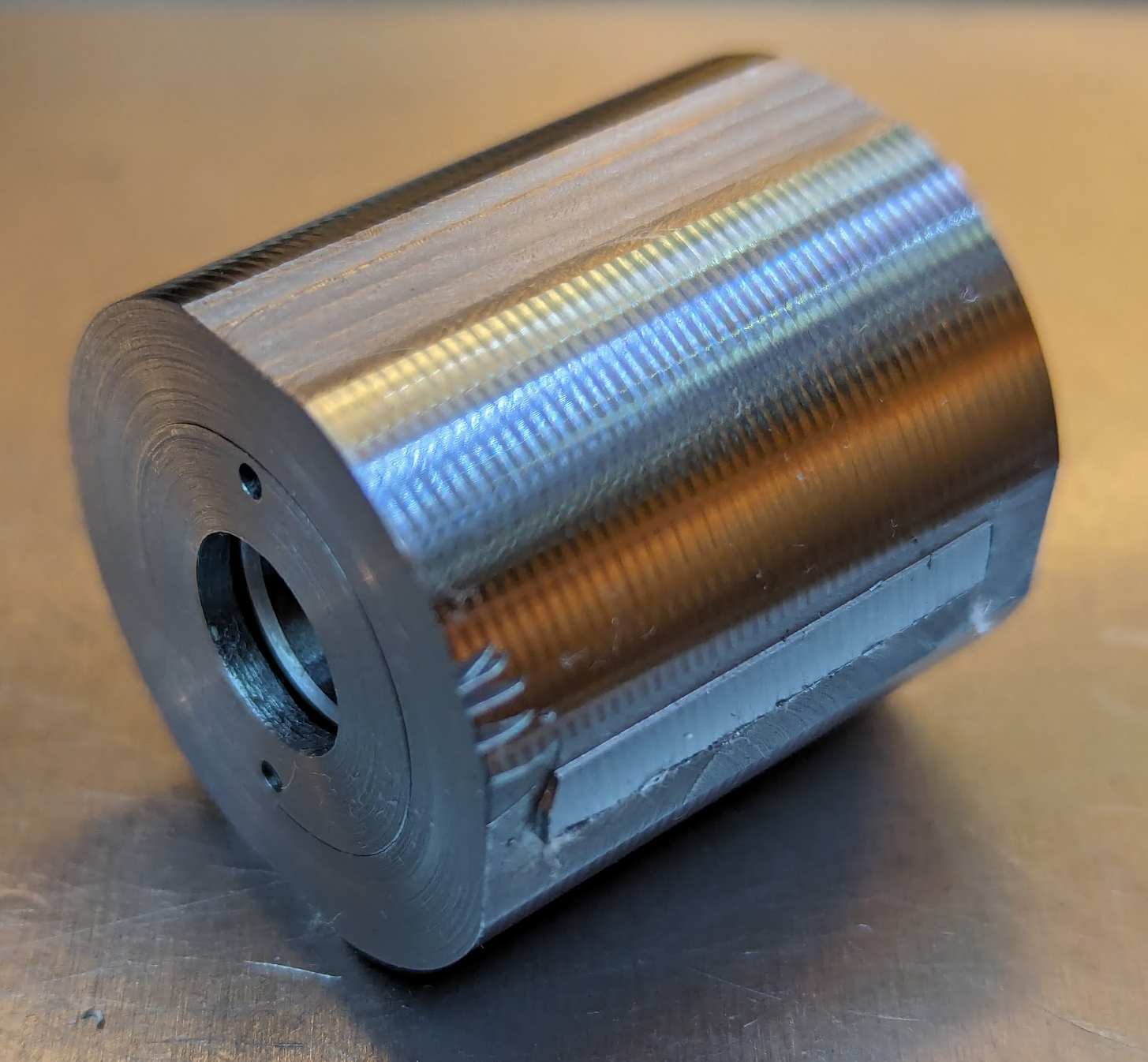
Fortunately, the ugly fail on the side of this picture (I ran the cutter in the wrong direction and probably hadn’t clamped it as tight as I had meant to) is in material to be removed later in the manufacturing process:
The Broach
It was finally time to make my first actual broach!
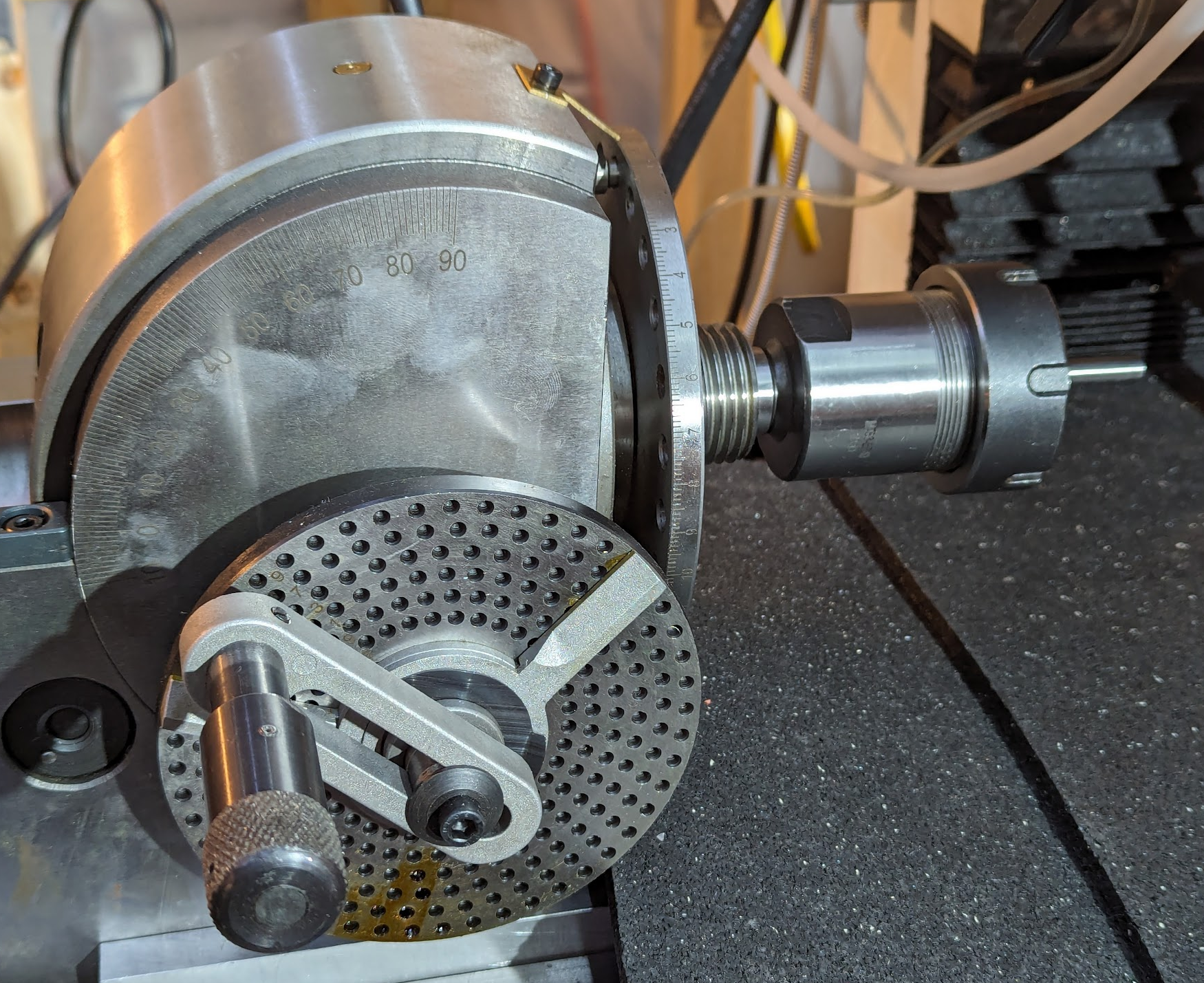
The Hemingway instructions say that dishing the end of the broad doesn’t matter. I don’t believe that after all the HSS tooling I’ve ground and experienced various relief angles, but I saw the idea of dishing the end by just starting a drill bit into it. I used a 120° spotting drill and put a cone in the end of the rod, and then pulled out the dividing head. I set it at -2.5° (that is, pointing 2.5° under horizontal), chucked the rod, and put in an endmill.
Then I discovered that the chuck got in the way. It was just too big. Fortunately, I realized that I could remove the chuck and use my MT3-ER40 adapter in the dividing head’s MT3 taper, which gave me the access I needed. Unfortunately, I ended cutting the broach about .002" under nominal size (I was shooting for a slightly oversized 6mm broach and ended up undersize) but decided to finish it to try it out. I hardened it by heating it with propane to cherry red and then swirling it in water, then tempered it back to straw. I touched up the faces with an arkansas stone.
I drilled a 6mm hole in a piece of 6061 aluminum and loaded the broach into the holder. It broached smoothly and I locked the screws now that it had self-located to the correct offset.
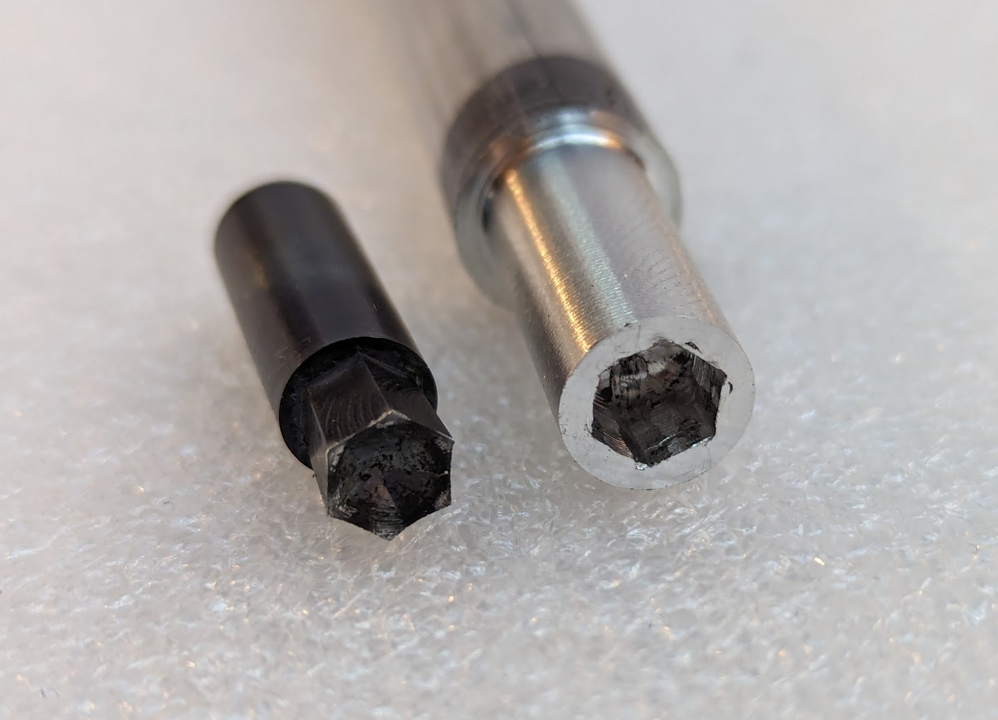
I can kind of fit a 6mm hex wrench in there, but I’ll start over again to make new broaches the right size.
Then I took the body off the shoulder, put 638 retaining compound on the sliding surfaces, assembled it with red loctite on the screws, again drilled 6mm and broached, and this time tightened the screws for good.
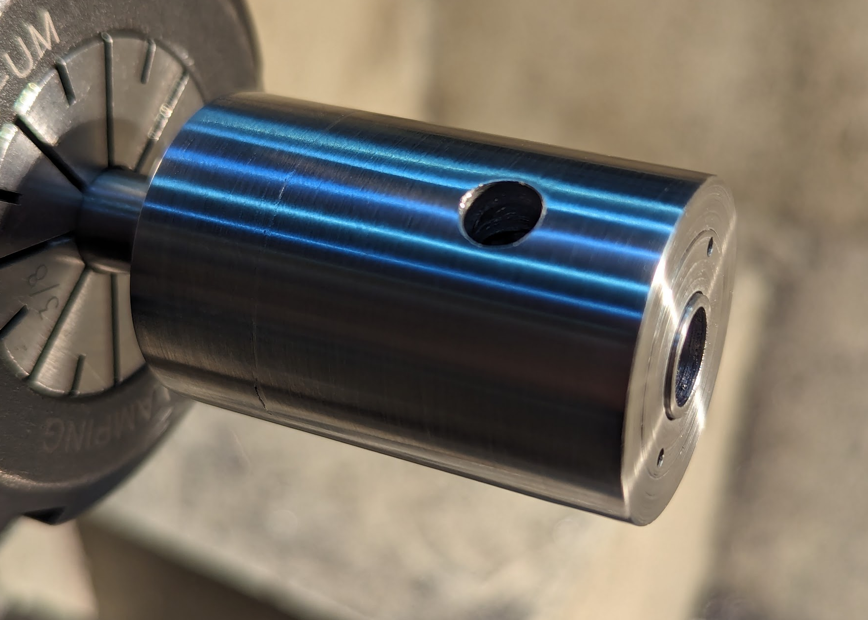
A day later, after the retaining compound had fully cured, I turned the whole permanently assembled unit down to size (removing the previously-visible evidence of a mistake). I did this with the ground and polished aluminum inert for low cutting force, but that didn’t leave it with the shine I wanted to see. I then polished it with 80, 200, 500, and 1200 grit to bring out a nice shine.
And I ordered 8mm drill rod in both O1 and A2 from McMaster so that I can make more broaches, and enough so that I can start over if I make a mistake. ![]()
Despite the fact that I went down the design-your-own rabbit hole, I’m glad I started with the Hemingway kit, and I recommend it. It’s a better design than several others I have found on the internet, and they are responsive to support questions.
Epilog
I have made drawings for the scaled-up design to take 1/2" broaches 1.75" long (another common size), and before even starting on making that, I have come up with an idea for a floating broach holder that doesn’t need adjustment, but instead self-centers, like the Hemingway design does before being locked in place. I think that it would be possible to have a single holder accommodate both the 8mm x 28mm micro broaches and the 8mm x 1.25" (really, mixed units…) standard length without any adjustment. But I haven’t put that in CAD yet to be sure. And I’m not sure I will. Probably I’ll move on to other tasks.