I got tired of the large and kludge’ey controller that I built from LO electronics.
I am about to complete a new LO lift table controller and I will post on it soon.
It uses and arduino/easy driver and joystick and fits neatly in the bay.
In the process of thinking about how to control the table from the job I stumbled across the fact that C3D and Lightburn can control the tables stepper. Clearly I haven’t been following close enough on those forums
…
It makes sense for me to better understand how the table is controlled from @LightBurn_Software and to see if what exists is better than what I just built.
Never fails, seems like something better always raises its head just as soon as you finish your own version…
I am researching these questions so if you already know the answer it would save me some time. Otherwise I will keep searching.
I have a smoothie 5 board that I bought before @raykholo board was available.
What motor on the smoothie 5 would be used by Lightburn to control the table.
I think its the gama (configuration file) or motor 3 which is often used for the Z axis. I assume that the end stops would be connected as a Z axis as well.
Can you control the up/down of the table from the UI in Lightburn when you are not running a job. I could not find a place in the Lightburn UI that was just up/down control. If it cannot how do users control the position of the table outside of running a job?
Is it the “Focus Z” button which in my tinkering does nothing, but then again I was not connected to the machine when I tried it?
Is special firmware needed and if so where can I get it?
Does Lightburn control the table using Gcode commands to the Z axis?
You would use the Z driver on a Smoothieboard, set up the steps per mm and max speed/ acceleration values, and it would be controlled by gCode. LightBurn does indeed have jog buttons for the Z axis.
LightBurn then has more advanced functionality including multiple passes and material library. This relies on the material thickness being set to work properly.
Start by configuring it and issuing gCode to verify that it moves properly.
IIRC The biggest issue that most people had was the amperage of the motor on the LO table draws like 2.5A and the chips were rated to 2A IIRC. So they would get hot. Maybe swap out the motor for a lower one? its not like its duty cycle is gonna be high.
The other way would be to branch out the signals to an external driver. I belive smoothieboards have the pinouts conveniently located next to the chips, not sure about C3D.
Thinking out loud…
I to date have built 3 controller protos for this thing!
When I built the first arduino controller (#1) I measured the current as much higher than the driver could handle and that always puzzled me because the motor specs weren’t that high.
I abandoned #1 and built an external controller with cheezy switches just to get running.
My guess was that the table’s mechanical resistance is causing the elevated current?
That is why I went the route of an external controller but I never really liked the implementation.
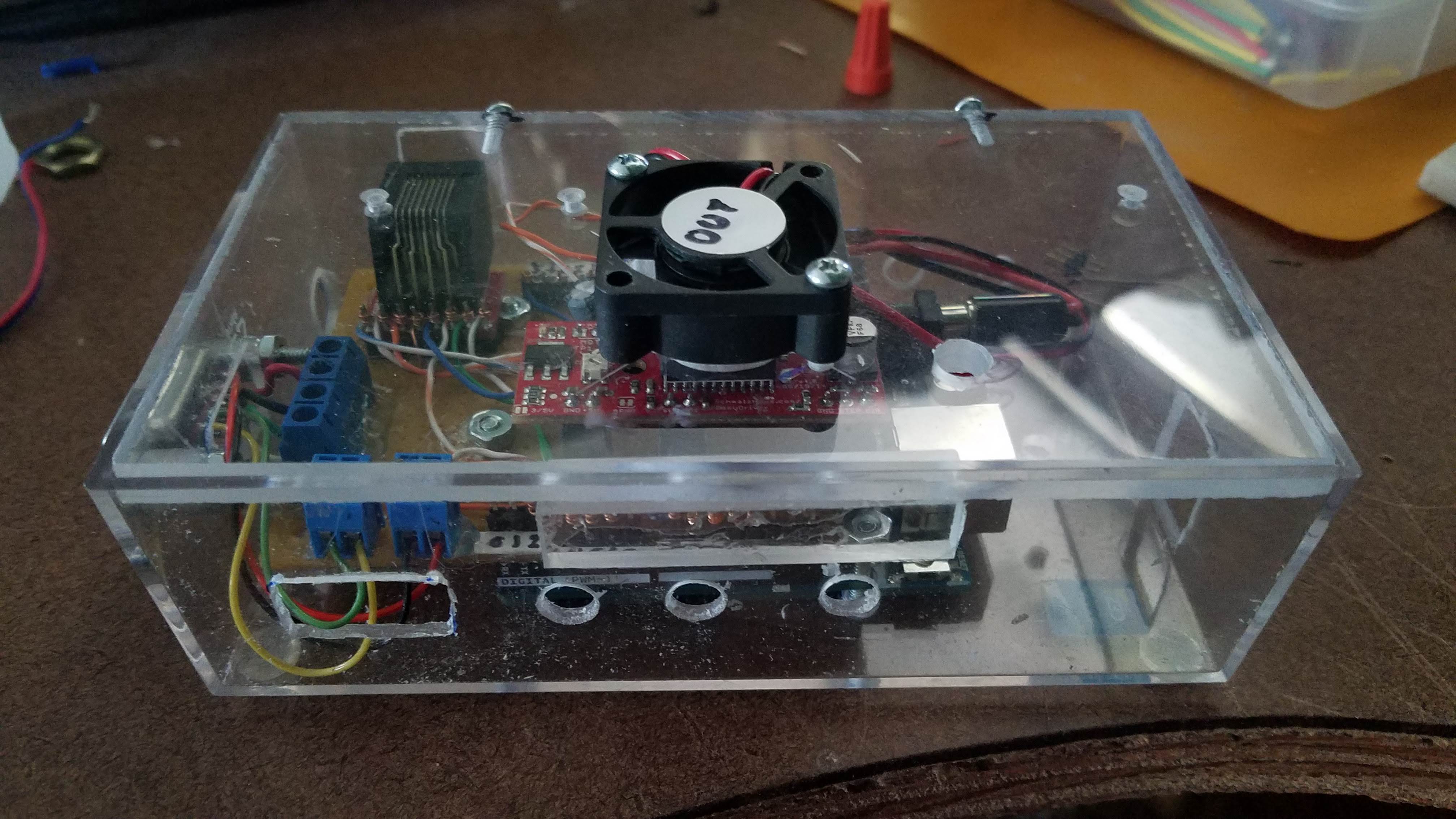
Then after seeing users searching for a lower cost controller that was arduino based I figured I would try again. Build controller #3 which would meet my needs and those wanting a cheaper solution. Along with this controller I adjusted out binding in the shafts and lubricated all the moving parts. I had to crank the current to max and add a heat sink and fan to keep it cool enough. This version is completely stand alone and has these features:
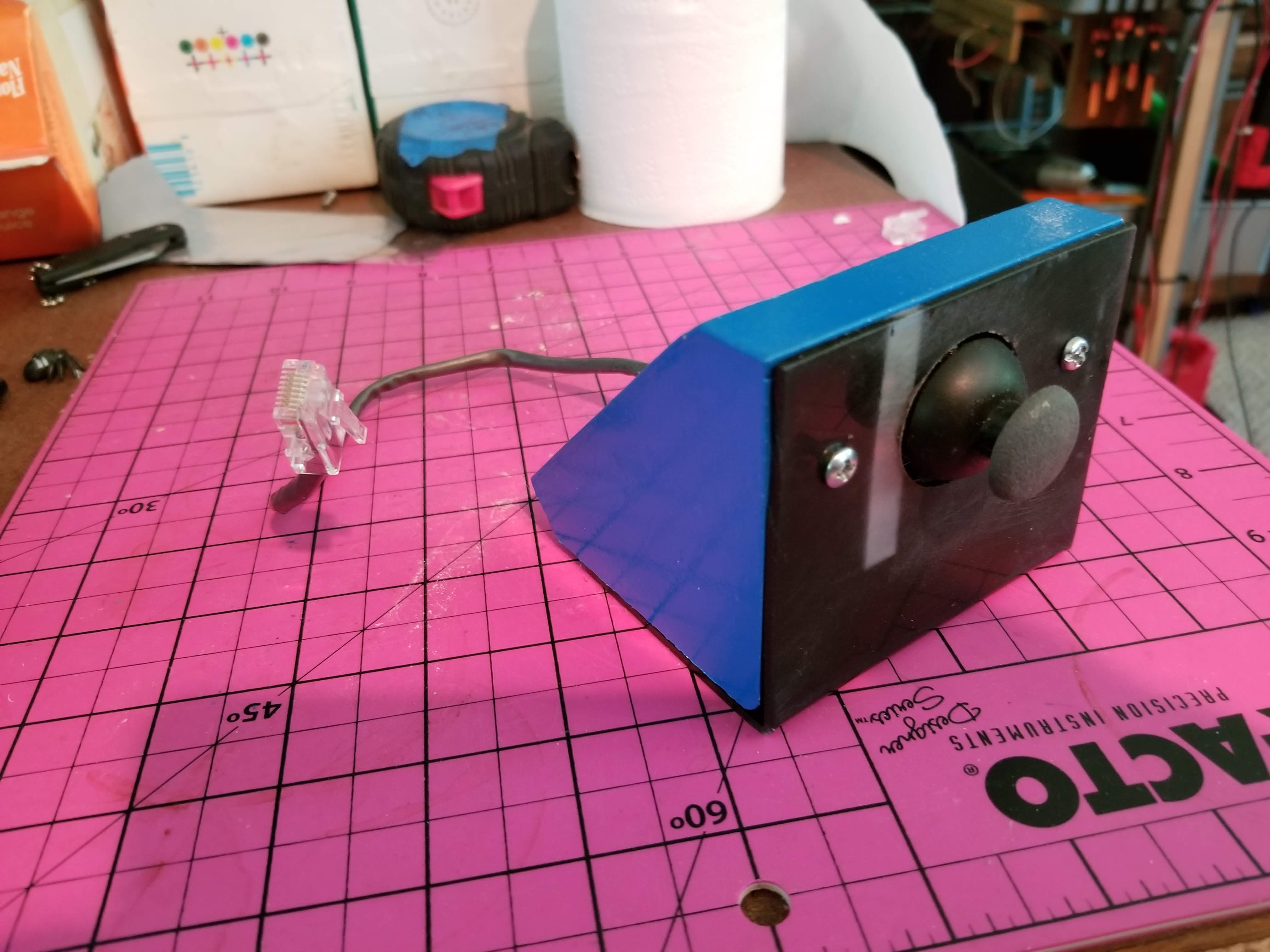
Up down motion using a small joystick mounted on the front of the machine
3 speeds with indicators set by the joystick switch
Endstop limit controls
Built in diagnostics
Open source code & schematics.
Made with an easy driver board and arduino both of which are pretty inexpensive.
Integrated 12VDC supply
It is run off of the LPS 24V [which I am now revisiting].
Then as I was researching methods to interface this with the software I found out that C3D and Lightburn already had this all solved quite elegantly interfacing an external driver with the stepper controls and treating the table like a z axis…nice! There are some cool cutting features that come with this setup when using Lightburn.
The base problem with just hooking a stepper to my Smoothie 5 seems to be that the integrated stepper chips cannot handle the current which dictates an external driver.
My choices seem to be:
Use controller # 3 standalone without program control.
Use a cut down version of #3 (just easy driver) and interface it directly with the control signals on the Smoothie 5. Perhaps the big easy driver" which can handle 2A.
Wire the motor directly to the smoothie M3 driver and somehow add a heat sync and fan to the board.
Let me know what you think I should do with controller #3. Is it useful to the community?
Perhaps those with stock controllers would find it useful???
Note: I also have a new mounting method for the LO table. Sitting it on the bottom of the machine does not insure that it is level so my new method references the table to the gantry. I will post that design later.
SOME SUPPORTING DATA … MOTOR
The motor from LO site: 42HS03 2A 2 phase 4 wires
The spec sheet says it will draw 1.4A.
Considering the table doesn’t really hold much load I would suggest testing it at lower amperage and see if it starts struggling at any value. For all we know it may be rated to 2.4 but capable of performing just fine at 1.5 or so.
I will try what you suggest to see what current it dies at.
My guess is the belt, pulleys and 4 screw shafts require more torque than expected since allignment of 4 shafts won’t be perfect.
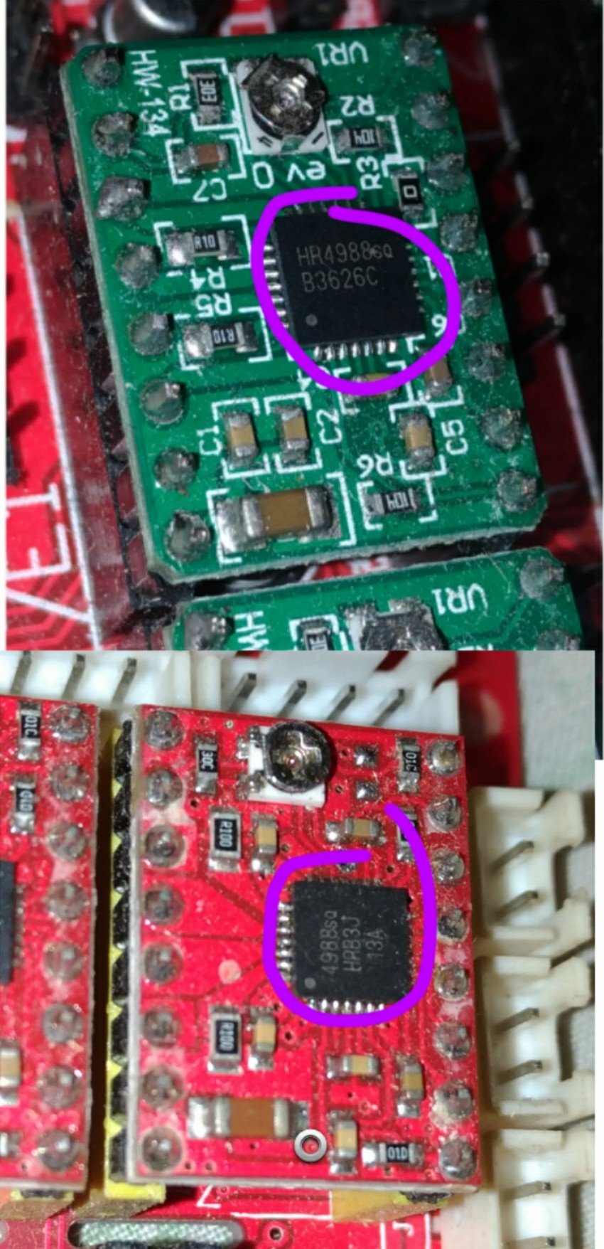
hi, excusme
week ago i bought some driver A4988, when it’s come i got HR4988 green color,and i’m see the chip it’s different with my oldest red A4988, like this