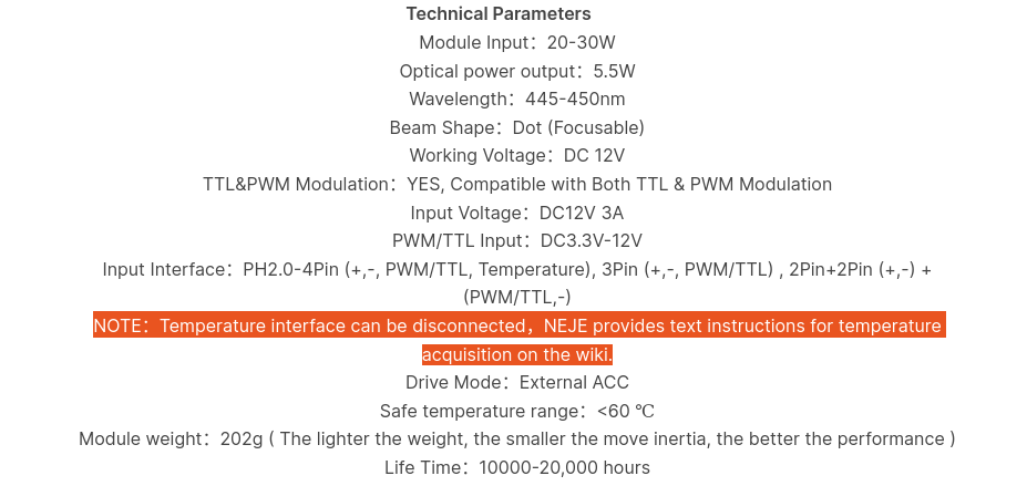
Any chance it’s a typical NTC100K thermistor? Those are cheap and plentiful. Should read ~100K at room temperature (25°C / 77°F) if so. Here’s an example table…
Doh! I hadn’t thought through simply characterizing the sensor by mapping the ambient resistance value to a temp/resistance table for a device… Thanks!
I could also heat the module with a heat gun while monitoring it with an IR gun and get some idea of the curve. Of course that will tell me the temp of the heat sync, not the diode.
The temp connection statically (no fan running) reads 13K at 65 degrees. The chart you provided maps 65 deg @ 18k.
I gave Bard a stab at it:
prompt: what temperature sensing device has a resistance of 13K at 65 degrees F?
Based on my understanding, the temperature sensing device that has a resistance of 13K at 65 degrees Fahrenheit is the LM35 Precision Centigrade Temperature Sensor. It is a linear integrated circuit temperature sensor that is calibrated to an accuracy of +/- 1/4 degree Celsius over a temperature range of -55 degrees Celsius to 150 degrees Celsius. The LM35 has a wide operating voltage range of 4V to 30V, and it consumes only 60uA of current.
This device is commonly found in a wide range of applications, including air conditioners, refrigerators, and industrial control systems. It is also used in many consumer electronics products, such as digital cameras and cell phones.
Here is the datasheet for the LM35 Precision Centigrade Temperature Sensor: [LM35 Datasheet]
This looks like a plausible device to use in this application.
However, I do not get where Bard got the association between temp and resistance for this device. If the device in the module is a LM35 then I am just measuring the static output resistance of the amplifier. I could prove this by heating the module with no power applied to the module and see if the resistance changes.
All that said I am not sure what I would do with knowing the temp anyway since I don’t know any of the thermal characteristics of the module/diode and what max temp values should be.
I have an interlock circuit in the laser power. I could add a contact to the laser interlock circuit that will open when some [yet to be determined] value of over-temp is reached from this signal.
I should also add a Temp output connection so that I can hang a voltmeter on it.
Thanks, now I have some more ideas on what I should add to the PCB.
## Detail

Uart detail: 200bps baud rate, one start bit, 8 bit data, one stop bit, no check bit.

Command Deatil:

[Header] [Length] [CMD_VER] [FW_VER & ID] [Temperature(int)] [Temperature(float)] [PWM_Input] [CheckSum]

* Header: 0xFF
* Length: length of command
* CMD_VER: version of this command
* FW_VER & ID: FW_VER << 4 | ID
* Temperature(int): integer part of temperature
* Temperature(float): fractional part of temperature(0-9)
* PWM_Input: pwm input read back
* CheckSum: check of command(not include header)
Looks… interesting. Not sure if it is a lot of use or gives reliable results (from reading the reddit thread)
Temperature based control appears to be common in communications and industrial lasers, where I guess protecting the diode is key, rather than max power!!
I plan to later upgrade to a more powerful module on my way to a 40W portable engraver (MoBeam)
NEJE is one of my choices for a newer model. I suspect many of these brands use OEM versions of NEJE.
One of the tests I should do is put a scope on the temp signal.
I found this interesting:…
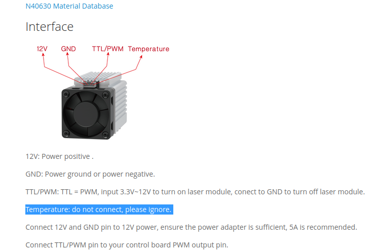
PWM spec: I wondered how 12 was mapped to a TTL [not] signal. 0~2V is completely turned off, and 2.5V~12V is fully turned on. There is no intermediate state, either fully turned on or completely turned off.
There are three types of NEJE modules. Analog, digital & new digital.
The “digital” models control the fan based on temperature. <37C = off. >40= on. I assume this control is all done in the module since these are specs for the module. The serial TEMP output feedbacks to the controller the temp and PWM value of the module.
A good first step, hopefully you see a digital stream
These do look like nice modules. I’m holding fire on upgrades at the moment since I’m broke and basically; the longer I wait the higher the Wattage per mm2 per I’ll be able to get when I have some spare change
That is exactly my plan with my big diode laser; keeping options open and a simple upgrade path as time, money and enthusiasm allow. (except mine is definitively not portable)
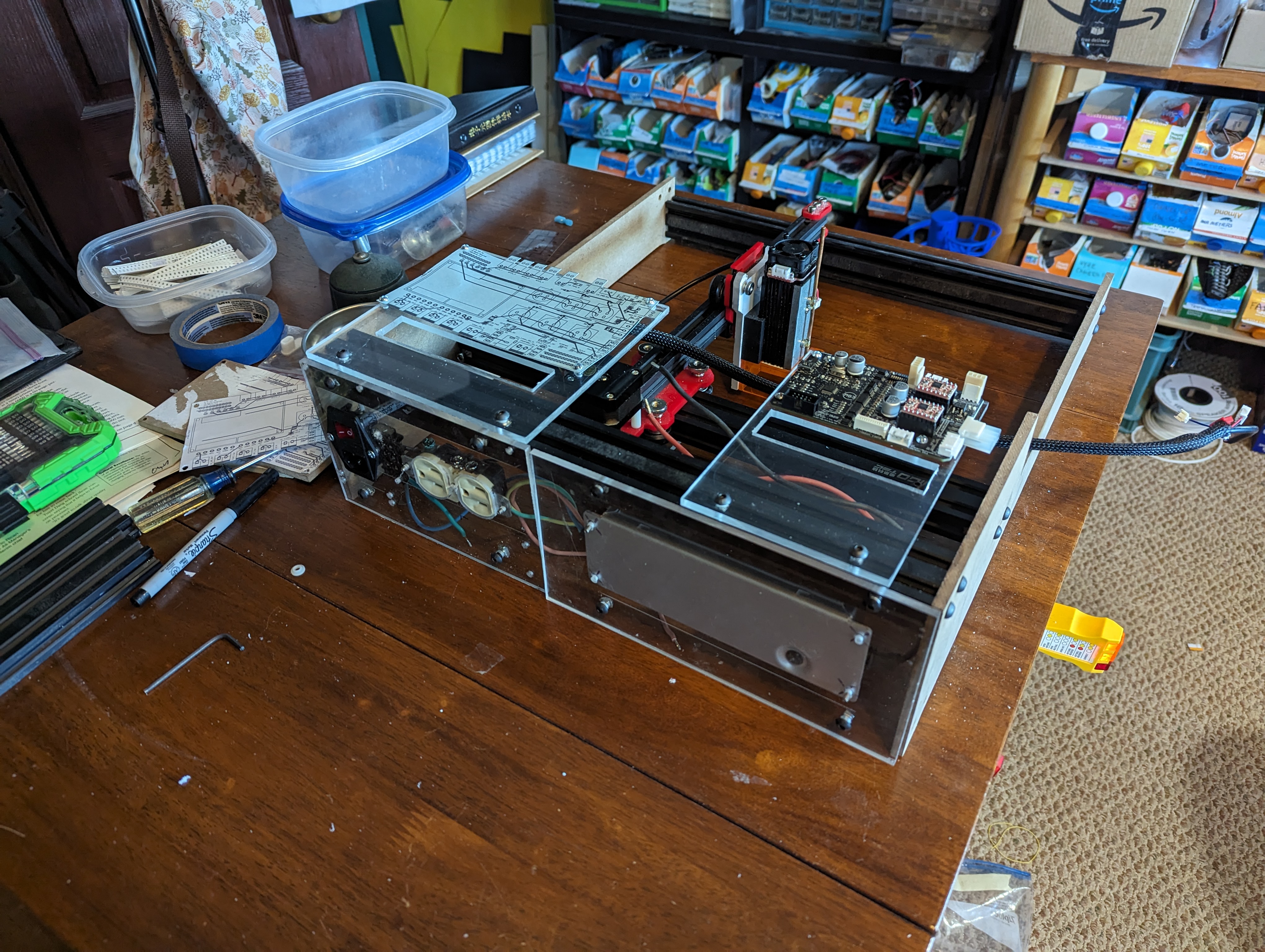
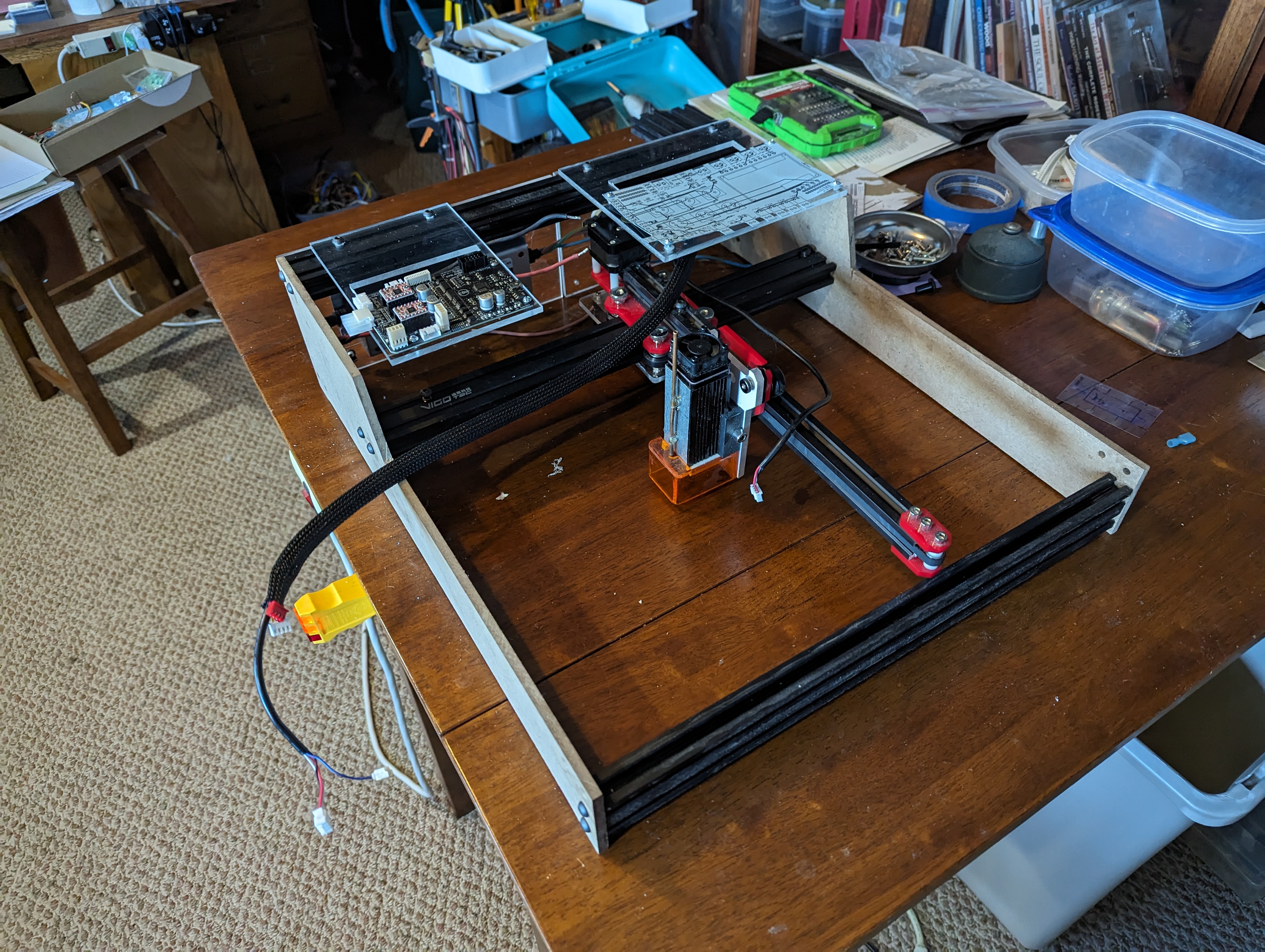
I wonder how far that arm could be extended if you put a linear bearing on the side of that extrusion and connected the tip of the arm to it. Nice setup.
Thought a lot about capturing the far end of the Y beam.
With my K40 I found that most of my work was engraving on small items or small areas on larger objects. I did not use it as much as I should have, the setup monitoring & maintenance were a pain. I am thinking of this design as an engraver equivalent of a shop router. I probably have a bigger area than I need but I figured that I could cut it back later.
So the concept of this machine is to keep the working area reasonably small, simple, and accurate with the ability to move the entire machine to a location on a surface. Also, include the ability to change the height of the entire unit for odd shapes.
I completely understand that and I have an original Ortur LaserMaster 1 which is used that way.
It has only a 160x150 work area but it’s great for most engraving projects.