I think these symptoms nets out to the following:
Proper operation:
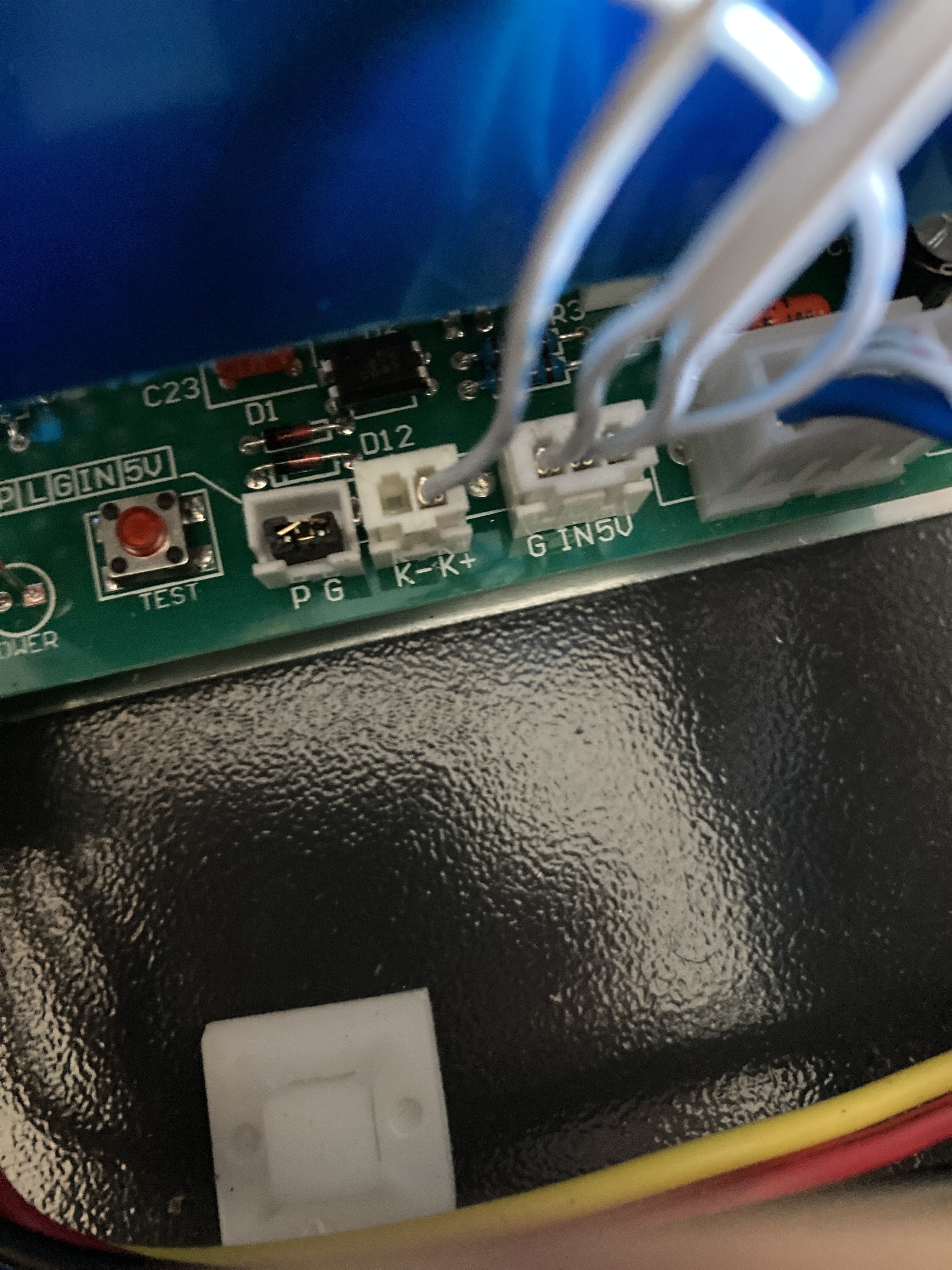
With the LV connector unplugged or the L pin disconnected the “test fire” button will fire the laser if it is enabled with the “Laser Switch” being asserted.
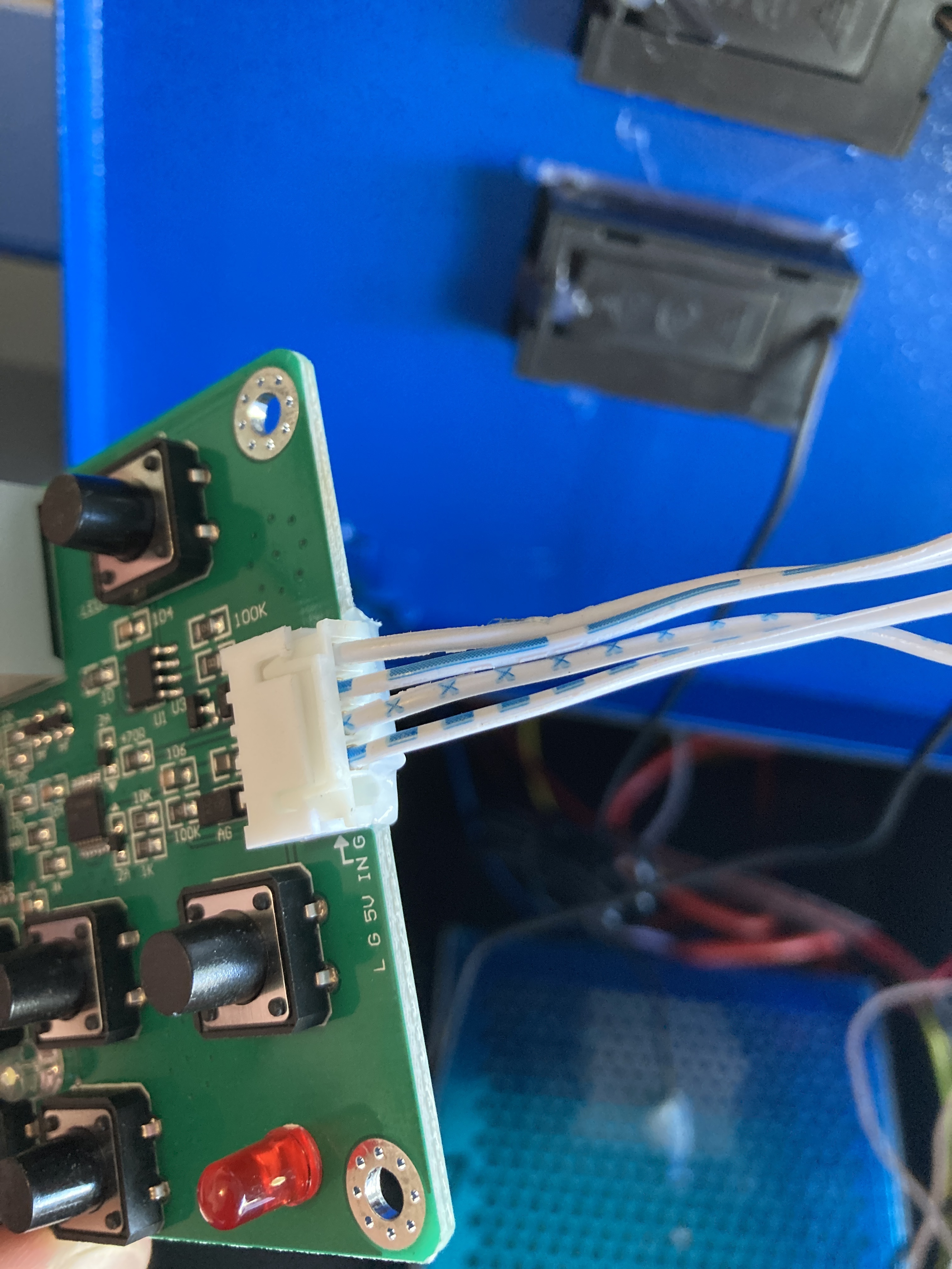
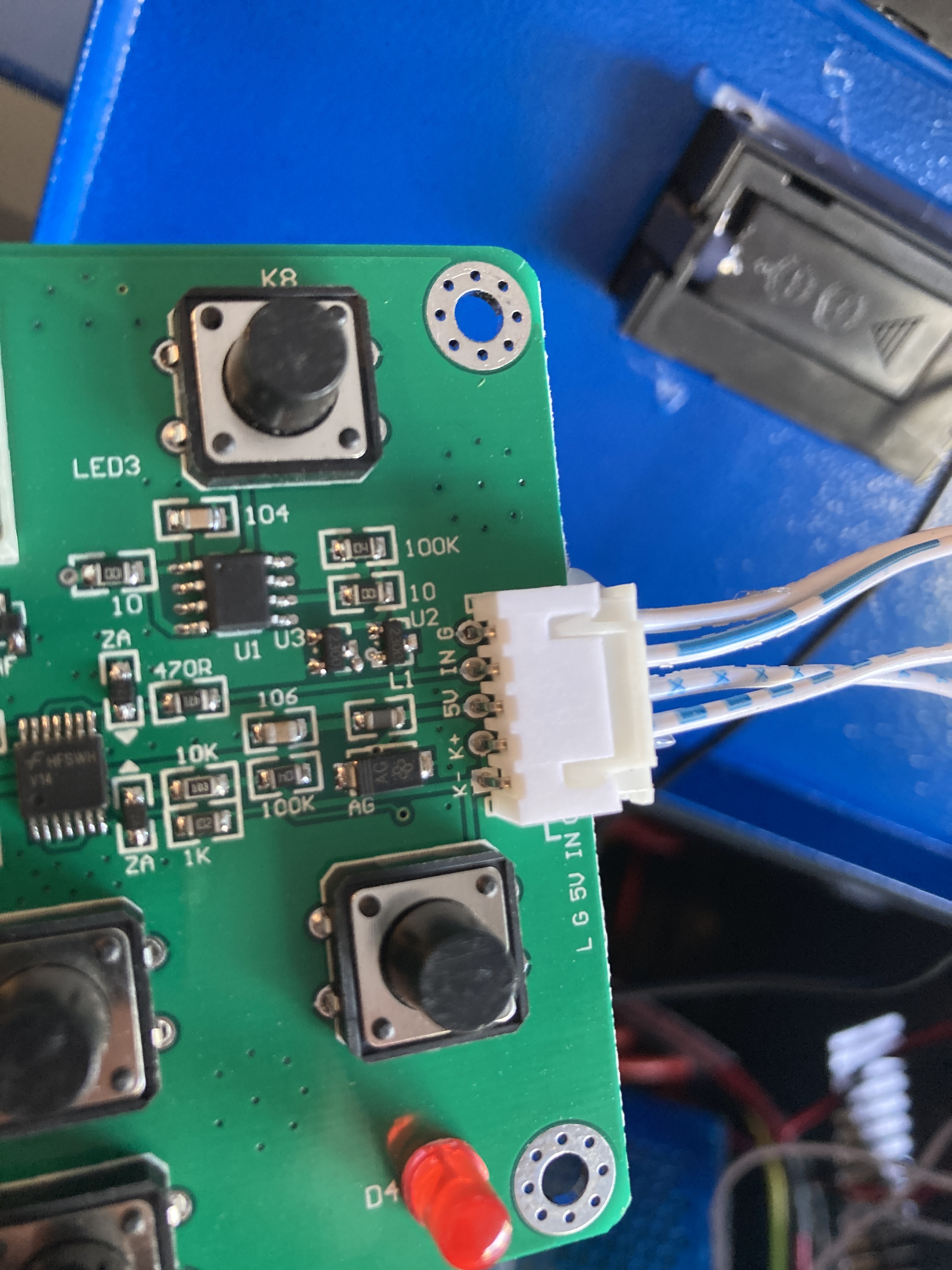
This is because in your machine the P&G is jumpered and the control panel controls the state of the K- to K+ connection. In the digital panel configuration, the L (in the LVPS connector) is not connected to the panel. The panel asserts A PWM signal on the IN pin to fire the laser when the test-fire is pushed.
Don's Laser Things: Understanding the K40 Digital Control Panel???
Improper operation:
Only when the C3d is installed: the machine turns on the laser at power-up. There is never a case where the laser should come on at power-up.
Symptom with Laserboard installed:
When the L pin on the LV connector is pulled
OR;
when the LV connector is not plugged in
… the laser is NOT turned on at power-up.
Conclusion:
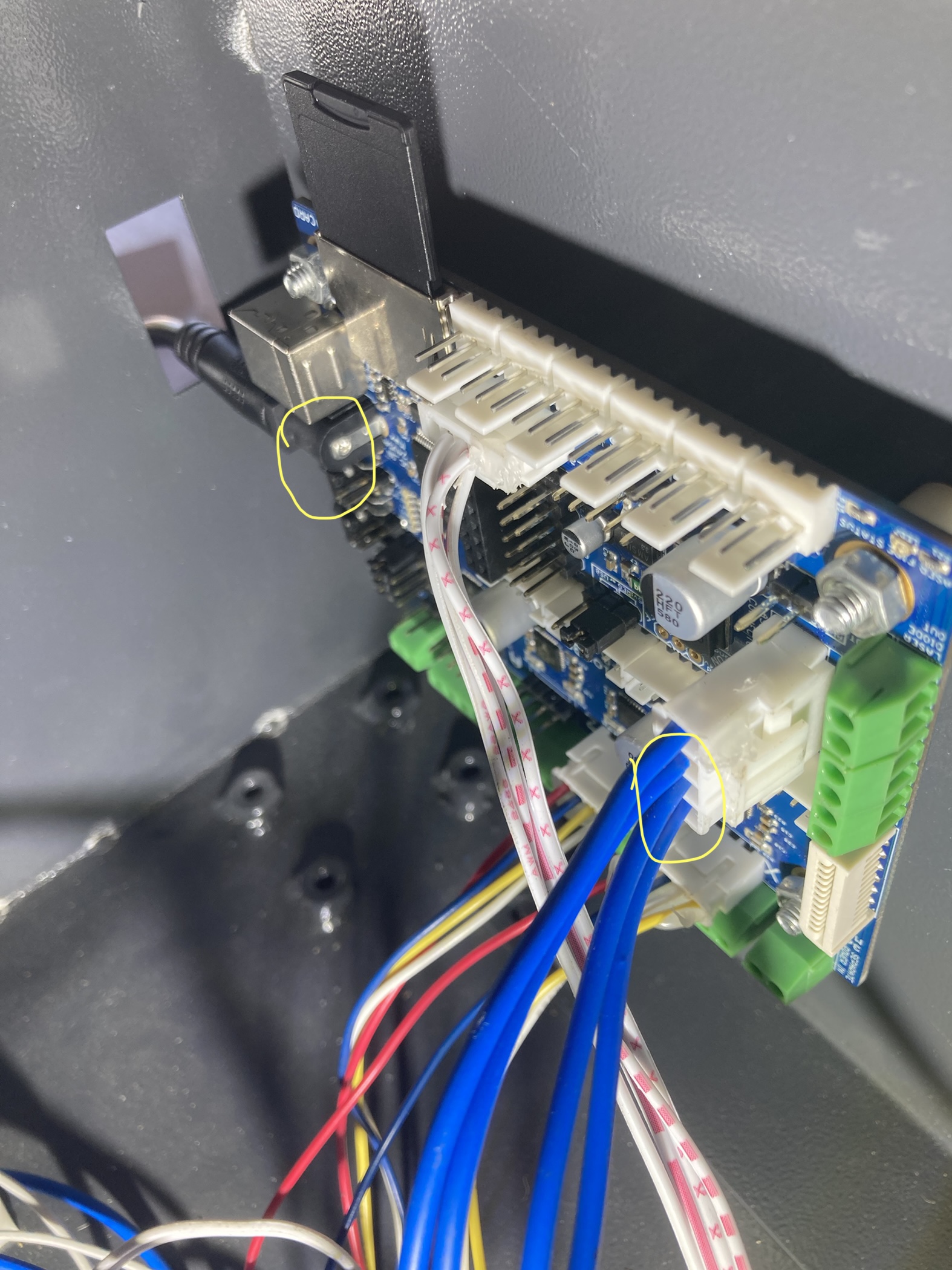
The C3D is holding the L pin on the LV connector low (gnd).
Gosh, this problem feels like de-ja-vu but I cannot find a thread on here that looks like this.
Test:
These are more sanity checks…
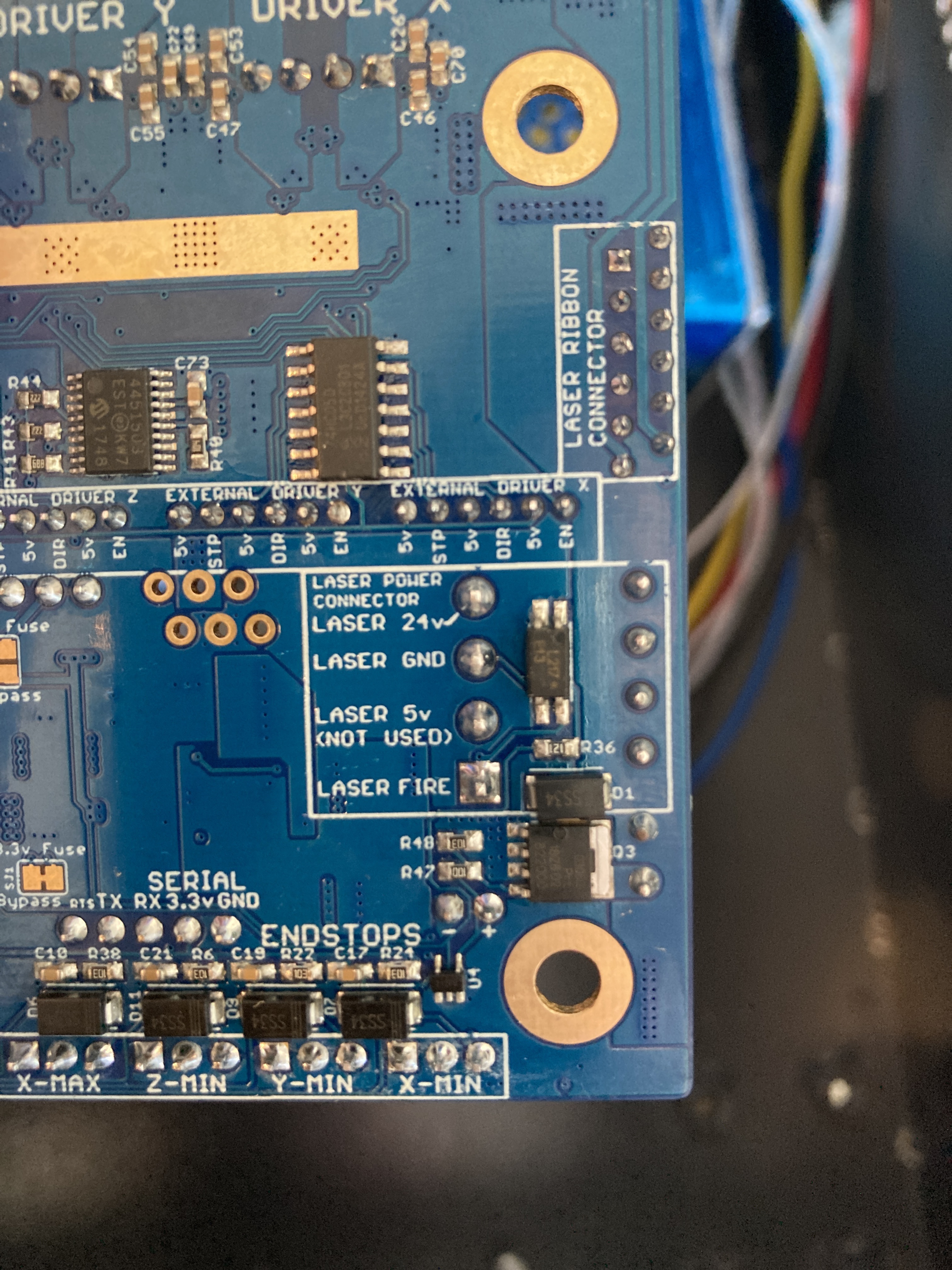
Measure the voltage [to ground] on the LaserFire pin of the LaserBoard with the power on with these conditions.
---- Measure Voltage on Laserfire ----
Do this one with power on
|Ref#|LV connector on C3D* |Volts on LaserFire @ C3D|
| — | — | — |—|
|M1|Plugged in |??|
|M2|Not plugged in|??|
*with the L pin inserted in the connector
Continuity test
With the power off
AND
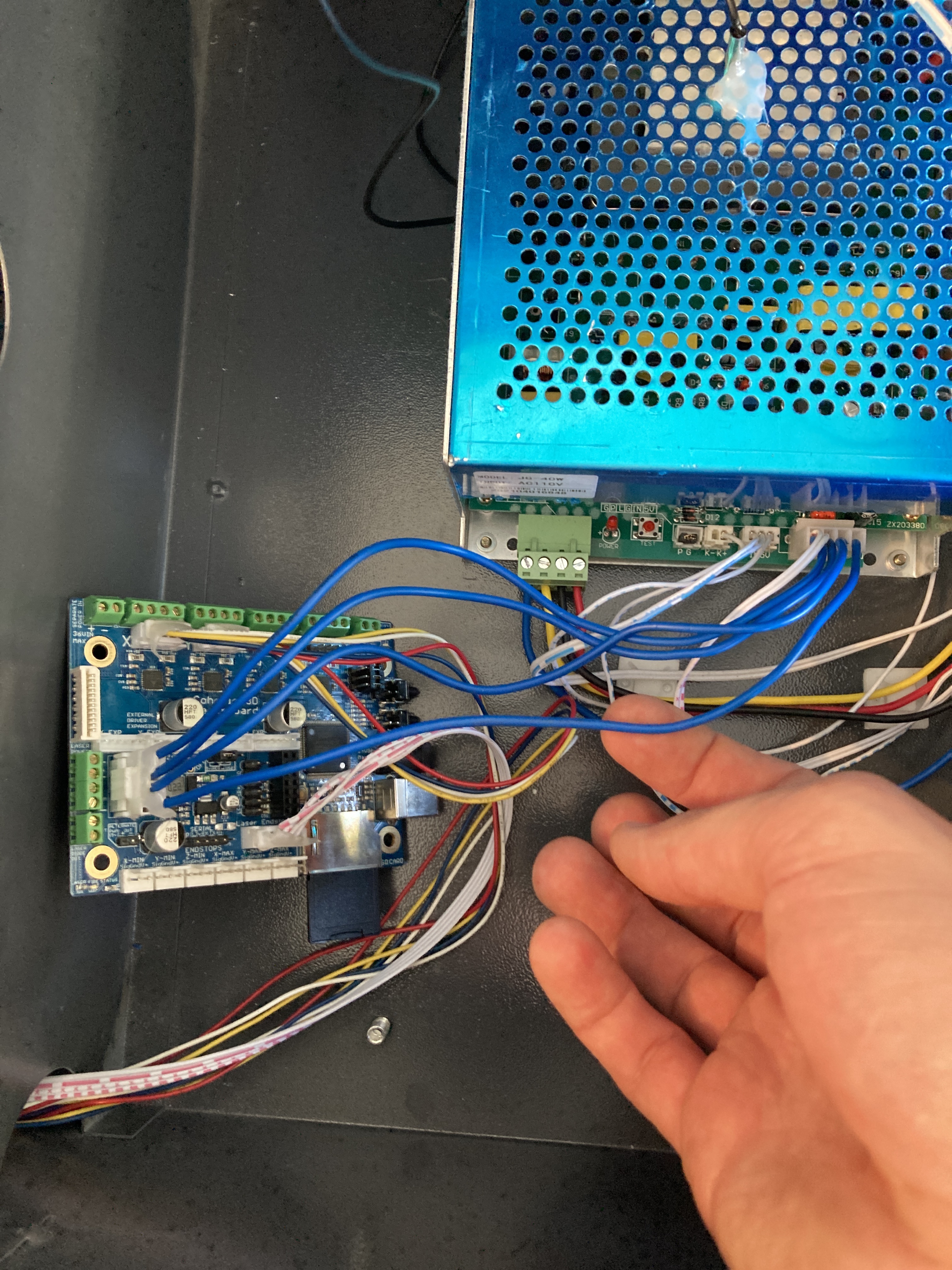
LV connector plugged into the LaserBoard
AND
LV connector plugged into the LPS
Measure continuity (ohms) between the grounds on these three things:
LPS-Laserboard =
LPS-Laserboard LVPS =
LaserBoard - Laserboard LVPS =
ALSO:
Can you post the ## Laser module configuration portion of your configuration file.
@raykholo
It’s been a while and I could not find the correct schematics for this board. I am just trying to see how the Laserfire pin is being driven in this board configuration. Can you point me to the schematics??