Laser begins firing on startup after C3D install

Machine: K40 with Digital Display and M2 Nano Board

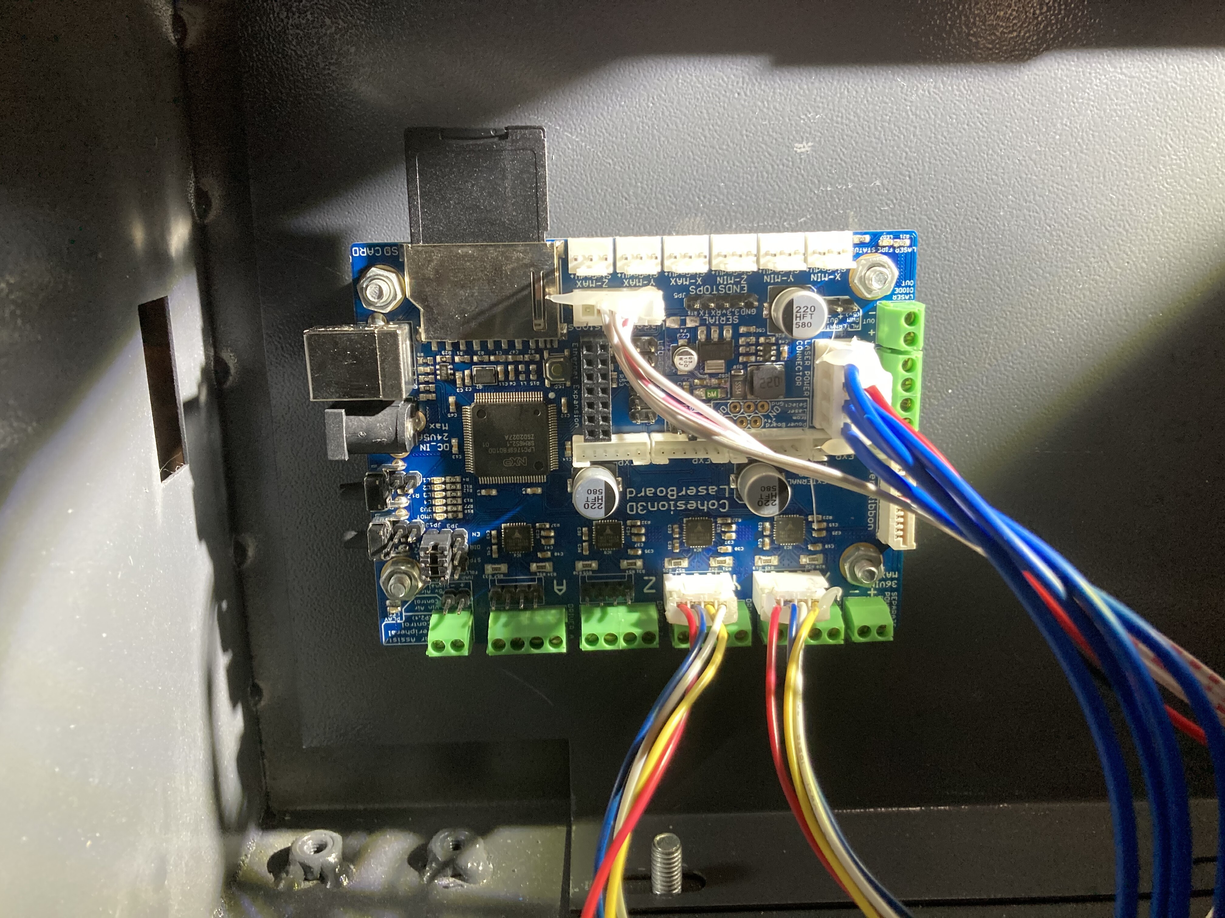
Board: C3D LaserBoard

Firmware: I have a new board and I’m using what it came with.

Problem: Brand new K40 with digital display and M2 Nano board. I did a quick test of the stock setup and the machine powers up, auto homes to the top left, and I am able to test fire the laser.

I then installed the C3D board as described on the website by doing the following:

  • Hooked up X and Y connections
  • Plugged in 4 pin, which has G, L, 5V, and 24V
  • Plugged in endstop connector
  • Connected DC into board
  • Connected USB into board
  • Plugged in SC card the board came with
  • Plugged AC power supply for board into outlet.

Had K40, water pump, and C3D power supply plugged into a 3-way extension cord.

LED’s lit up as described on the website for normal operation.

Hooked the USB to my Mac with Lightburn. I was able to jog the X and Y and send the laser to home. Prepared a test job by drawing simple squares. 1 in each corner and 1 in the center. When I tried to run the job I got the message saying there was an issue with the USB (I’m sorry I don’t remember the exact wording). I tried to unplug the USB and reconnect it and tried to run the job a few more times with the same result.

GFI outlet tripped. I reset the outlet and have moved the water pump and K40 power to an outlet and the LaserBoard to a different outlet.

Now when I power on the laser it starts firing immediately. Only way to stop this is to power off the machine or turn the power down to 0. I was able to jog the X and Y in Lightburn and send it back to home.

What’s interesting also is once I hook my computer up and have the board powered on I can hear a hissing from the laser tube. It continues even after I turn the machine off. It only stops if I unplug the DC cord from the board.

Please help me! I am at a loss and am confused what is happening.

I hooked up the M2 Nano board and it powers up normally. Homes to top left and I am able to test fire laser, but it does NOT begin firing on its own.

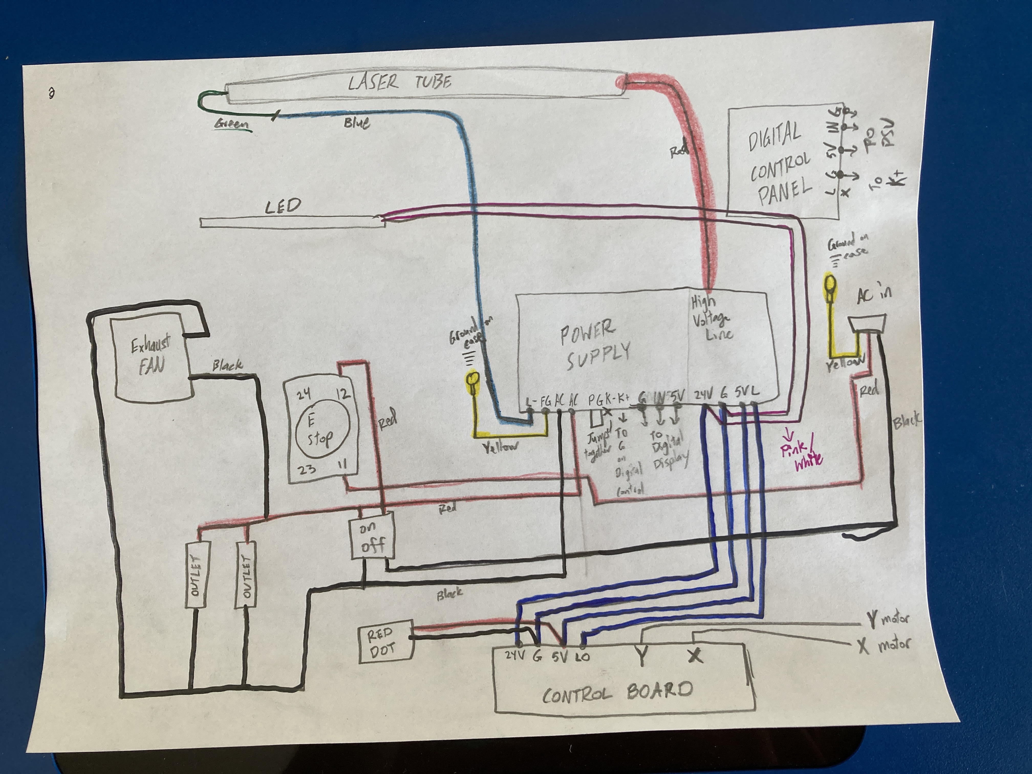
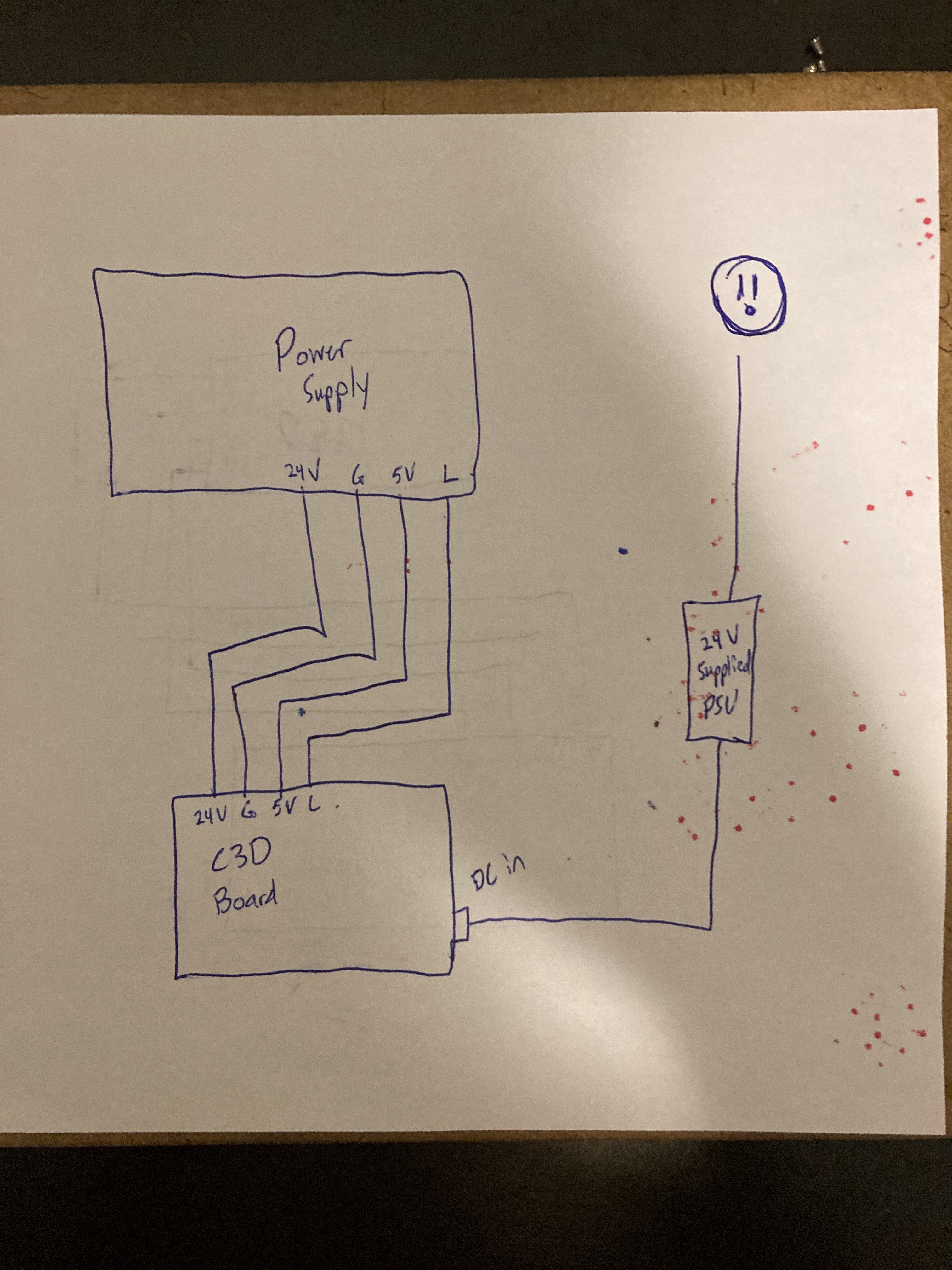
Here is the current wiring for the power supply and the C3D board.

I checked the config files that the C3D SD card came with and compared them to the stock files, they are still the same.


  1. What was going on when the breaker tripped?

  2. Try unplugging the rightmost connection on the LPS and then power up the machine. Does it still fire continuously?

  1. what does this mean do you have the C3D board on a separate DC supply?
  1. I had the K40, water pump, and power supply for the C3D board all plugged into an extension cord. Tried to run a job and I believe this is when the outlet tripped. Looking back I believe I had a small fan running too off of the same outlet.

I now have the K40 and water pump on one outlet and the board’s supply on another.

  1. I unplugged the rightmost connector and powered up the machine (not connected to computer at this time). Laser does not fire continuously.

I then plug into the computer and I hear a hissing sound coming from the top left of the machine (sounds like it is coming from the laser tube). I am able to job the laser around, send to origin, and send to home.

This means that I have the power supply that comes with the board plugged into an outlet, then plugged into the board.

I have the K40 and water pump plugged into a different outlet.

just to be clear:

When you plug the rightmost connector into the LPS and power on the machine the laser fires continuously yes/no

When you UNplug the rightmost connector into the LPS and power on the machine the laser DOES NOT fire continuously yes/no

YES. When I plug the connector in and power on, laser fires.

YES. When I UNplug the connector and power on, laser DOES NOT fire

I need to understand the DC power cable that goes between the C3D to the LPS.
This is the rightmost connector on the LPS and the 4 pin DC power connector on the C3D.

Can you draw how these are wired? i.e. point to point

How is the C3D dc supply (24VDC) wired to the C3D

Sure thing. I will post a photo as soon as I can draw it up.

Essentially the c3d board has a DC in plug (round) right under the USB plug. That comes from a completely isolated 24V supply that comes with the board. It is plugged into an outlet in the wall.

The 4 pin rightmost plug on the laser power supply goes straight to the c3d board. My original photos show this connection, it has 4 blue wires.

I will draw up the connections and post the photo as soon as I can.

I notice that there are black and red wires into that connector as well?

Yes, those power the red dot on the laser.

Dylan, you look to have the end stops and motors wired correctly and there’s only one other connector which could be a problem… that is the connector which leads to the 24v/Gnd/?/L connector of the LPS(Laser Power Supply). I would recheck that those signals match correctly the labels on the C3D connector. The “L” signal is what controls the amount of power to the laser tube so if that connector is plugged in backwards the tube power control would be uncontrolled.

Doug, are you referring to the rightmost plug on the LPS? 24v, G, 5v, and L?

I believe all of those lined up properly on the c3d board, but I will double check when I get home.

1 Like

yes, THAT connector. If the C3D board does not label each pin, find a drawing which does and verify the they match up. I don’t have a C3D board in mine but I put a Smoothieboard clone in and I use an external 24V power supply instead of the 24V power in the LPS. Pretty much the only wire I use on that connector is the L wire which is connected to a PWM output on my board. I do use the GND to make double sure there is a common ground but the key is that L connection for laser control.

What’s weird is when I swap back to the M2 Nano, things seem to act normally. I can adjust the laser down real low and do a test fire and it barely makes a mark.

Yet when I go back to the c3d, laser starts firing and it seems to be making a larger mark even though the digital display for power has not changed.

So confusing!

not really weird and it’s good that it does that. Once you check and double checked that 4 wire connector(24V/GND/5V/L) and know for sure it is connected to the C3D correctly the next place to look is the software you put on your uSD you have in your C3D.

The way that board works is it might have firmware already loaded but it will look for a config.txt file and load those settings every time the board is powered up. If for some reason you want to update the stored firmware, you’d copy the firmware file as “firmware.bin” onto the C3D uSD and then power down and power up the C3D board. If it read the firmware.bin file correctly it will have been renamed FIRMWARE.CUR but again it will use the config.txt file for configuring things. Things like if the PWM for laser control is active High or active Low for example and what pin on the board is doing the laser PWM control. Once your system is working, it’s a great system to have.

Are you also posting to the Cohesion3D forums or is this the only place you are looking for help?

I’ve looked at your pictures and I looked at the Cohesion3D sales page for the C3D and they show two different types of connectors coming from the K40 to the C3D and one looks just like yours and the locking tab looks to be in the correct side as per their image. BUT, I would not put it past a K40 manufacturer/assembler putting the wires in that connector backwards and putting the connector on backwards to make it work. So just tug on the blue wires a bit to see which one goes to which pin on the LPS and make sure they are going to the proper pin on the C3D. Once that is all set, I think the next step would be getting firmware and config.txt file and making sure your default software setup is as expected. Be careful if running Windows, it will sometimes change the name of config.txt to config.txt.txt and both files need to be exactly named firmware.bin and config.txt

My guess is that the L pin on the LPS is being held low from some yet to be found problem.

I also suspect some kind of grounding problem because you should not be blowing GFI and need separate plugs for the DC supplies.

I do not think this has anything to do with the PC since the symptoms are that the machine fires the laser as long as the low voltage cable is plugged into the LPS irrespective of anything else.

To verify the “L” theory you can also just remove the L signal from the LPS connector and plug in the cable and see if it still fires continuously.

FYI. @Dkwells is providing a wiring diagram…

Here is the wiring schematic STOCK.

Here is a basic drawing showing how the C3D board is connected to the LPS and how it’s own power supply is hooked up.