Could someone please help me figure out how to properly and safely connect the new power supply?
Have you seen this from @donkjr? He has a lot of useful info on his blog, and it’s fairly heavily interlinked.
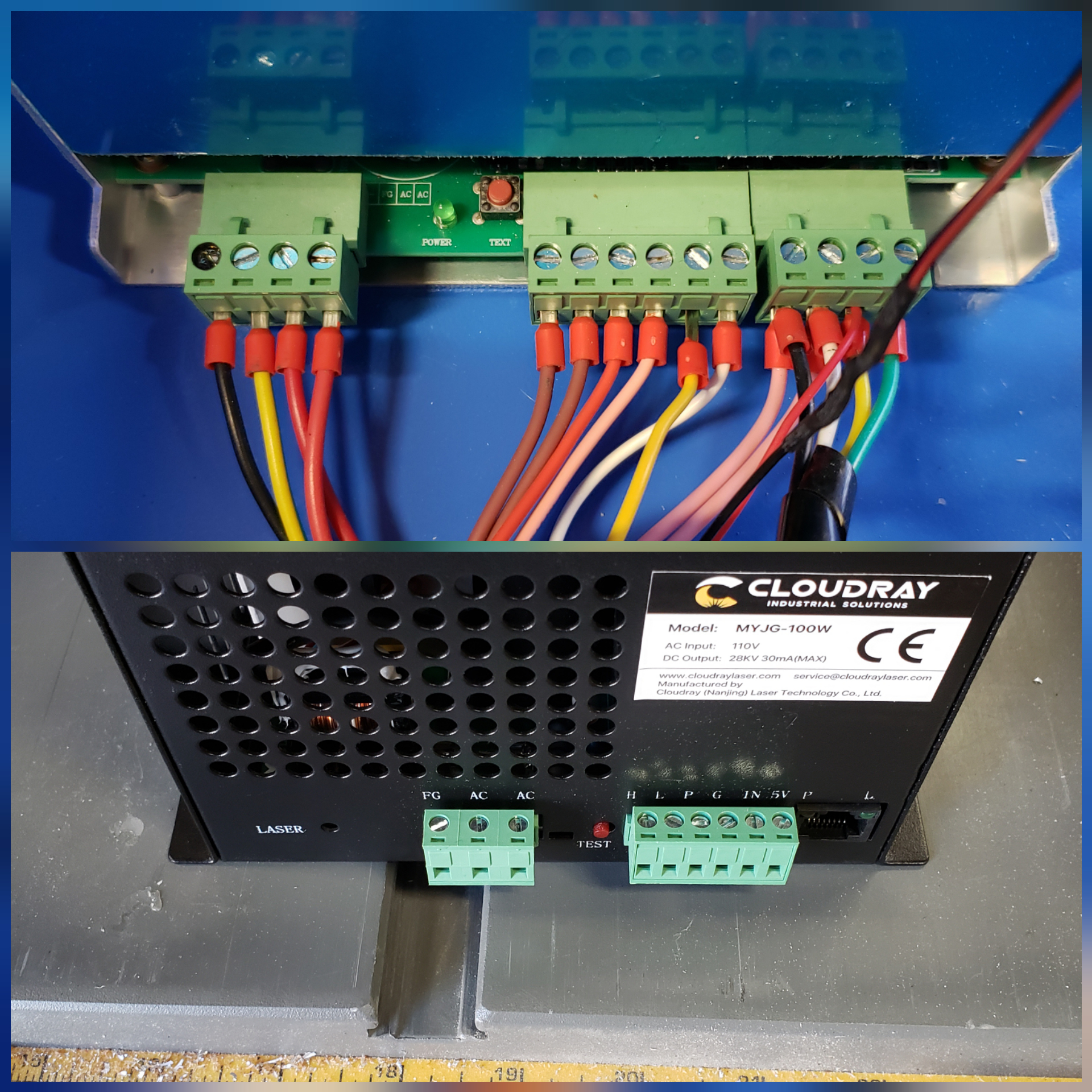
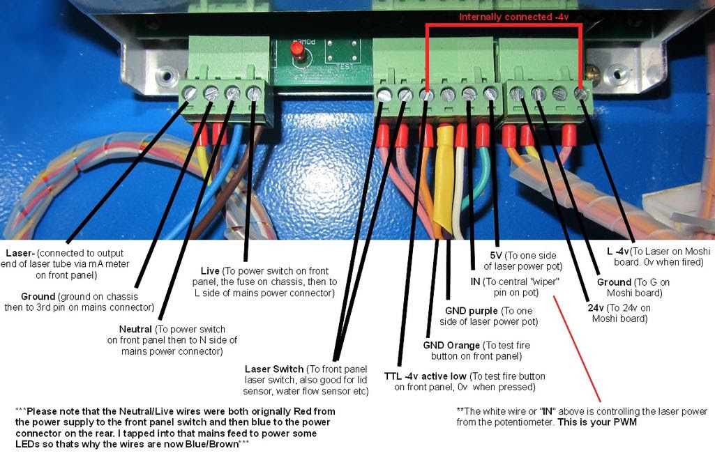
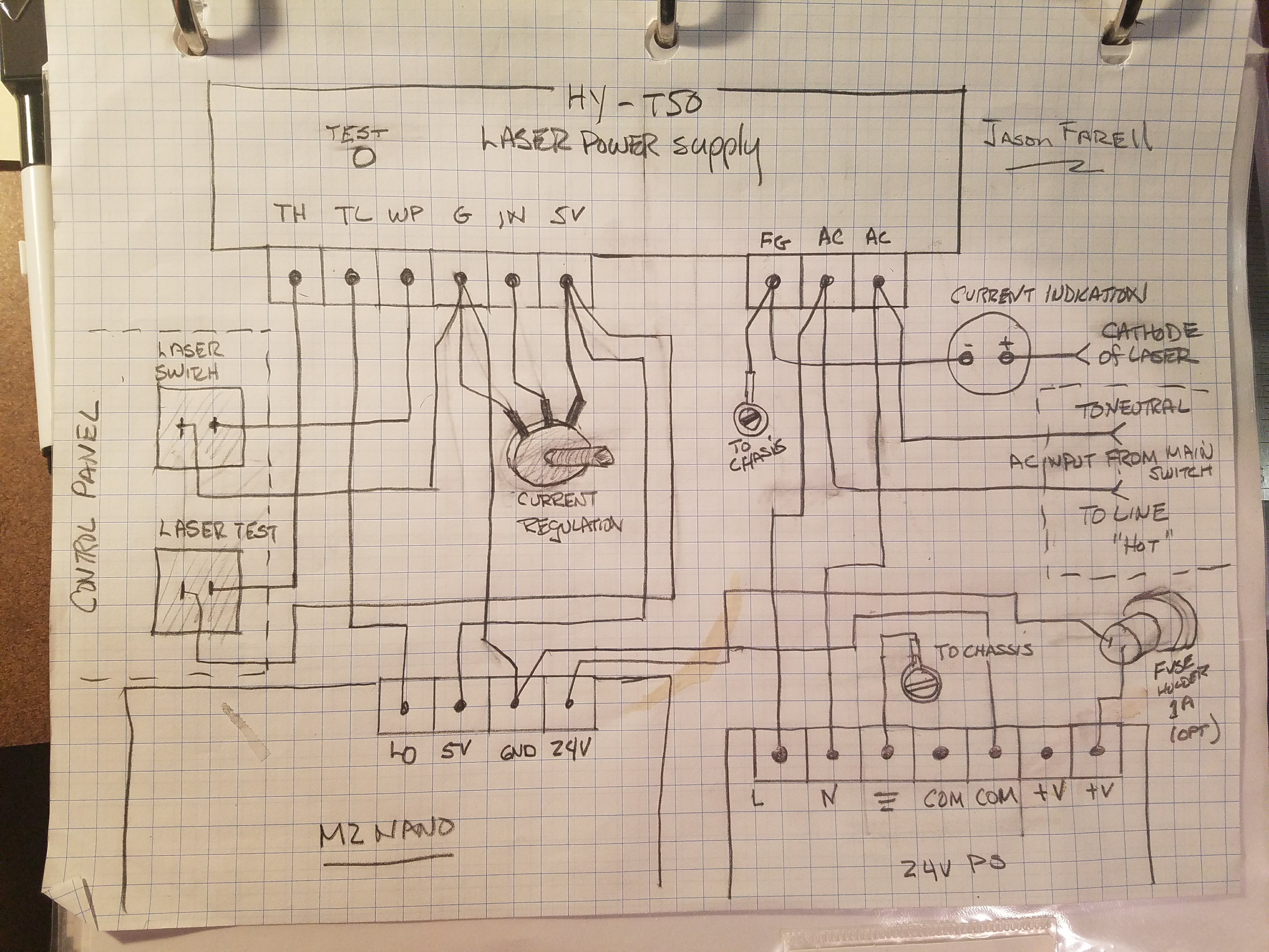
From that, here are labels for the LPS connections on the old LPS:
You probably already know, but you need to also have a separate low-voltage power supply for the controller board; the Cloudray doesn’t supply both.
TH Input Signal On-Off laser control,TH≥3V, emitting laser; TL≤0.3V, no laser. TL Input Signal On-Off laser control,TH≥3V, no laser; TL≤0.3V, emitting laser WP Input Signal On-Off laser control,TH≥3V, no laser; TL≤0.3V, emitting laser G GND This foot must be connected well with the laser machine shell and the ground of control board. IN Input Signal The control of laser power: Both 0-5V analog signal and 5V PWM signal can control the laser power. 5V Output Power Output 5V, the maximum output current is 20mA. Note: WP = water protection, this is an interlock loop for the water pump.
Looks like TH = H, TL = L, and WP = P for the labels on your supply, but otherwise the same as what he describes as a type B LPS.
There’s lots more there on his blog! Definitely check it out.
4 Likes
Assuming:
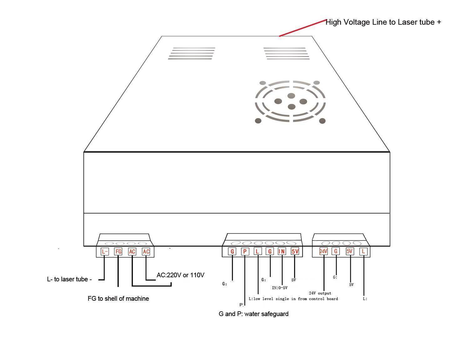
- This is your supply: https://www.cloudraylaser.com/products/100w-co2-laser-power-supply-myjg-100w-lcd?variant=15433062350899
- you are connecting to a stock controller on a K40.
This drawing is not for the exact supply your using but the connections are typical for this style control.
The white wire on the back:
You may have a white wire on the back of the supply. It is usually intended to be connected to the cathode of your laser tube and is grounded internally. If you have a panel ammeter that would be in series with this circuit.
Looks like this supply has a built-in ammeter so this white wire may need to connect to the cathode circuit directly, I don’t know if also having a panel meter in series would be a problem.
There are no installation instructions on the cloudray site regarding this wire.
You could contact support and ask how the white wire should be connected.