Cooling issues aside, my experience has shown that some materials don’t cut, they ablate. I’ve tried cutting foam core plywood and that is a total waste of time. Same with cork. I have cut high quality 3mm birch plywood at least a thousand times - no problem. Like one other user suggested, go back and attempt to cut some birch plywood to see if the problem is the laser or the material. And rig up an air assist system system. It’ll clear the kerf as you cut.
I would say that the laser and LPS are in good shape.
The problem is probably in the optics.
MDF is much harder to cut then plywood because it has a much higher content of Urea-formaldehyde (UF) resin / glue. UF really doesn’t like to burn due to it’s high nitrogen content.
A good air assist can help some, but it’s not a huge help. In my experience, cutting MDF with a K40 laser requires slow speed, higher power and multiple passes.
You’ll also ended up the a very chard edge. I’ve found using a plastic bristle bush in a rotary tool to grind off the char the works the best for char removal. It’s a bit messy and I strongly suggest wearing a good dust mask.

2 Likes
Yes I have gone back to first principles and I need to get it to cut 2.5mm birch ply first which it did do early last week
Yes I am just concentrating on getting to a position where I can cut 2.5mm birch ply again which was without air assist then I can move forward. Whereas it was flaming before air assist does seem to work well so not sure what the problem is so trying to re-align the mirrors again.
My comment about air assist was more about trying to improve the air assist for cutting MDF. I tried adding a secondary close high pressure directed stream of air from an air pump and did seem to help much with cutting MDF.
Air assist is a definite must to prevent flame ups and does help with most cutting. ![]()
1 Like
That’s good to know. As the last few times I have aligned the mirrors, they were not perfect but good enough to cut 2.5mm birch ply, I did want to do a proper job this time and used the guide from the site. Using tape sort of works ok if it is only you looking at the results but indenting where the hole is is iffy at best with the fixed mirror with its confined space so I produced a jig which goes over the mirror cover

and stick the tape to that so there is a clear centre of circle to aim at.

From this I did have to move the fixed mirror back so ok so far. I got a reasonable result hitting the Y stage mirror which presumably means the beam is running true down the Y axis but I noted I seem to have a problem with aligning the Y axis mirror X stage mirror which tracks horizontally as you move from A to B as it has run out of adjustment.

As you can see I would not expect the adjuster to be so angled and both screws have run out of adjustment. Is maybe the gantry not true as the bracket does seem to in line with where is should be or is it that I need to move the bracket which only has adjustment to move into cabinet? The horizontal is the issue not so much the vertical. I did not think it was worth continuing until you had time to comment.
Hard to tell but with the jig in place does the tape sit proud of the actual mirror surface?
Could that be affecting the alignment?
If the mirror alignment instructions tell you to put tape over the mirror I sure hope it also tells you to NOT burn through the tape. I repeat, do not burn through the tape. It will splatter hot glue onto your mirrors and make it very difficult to clean off. One trick others have used is to stick a coin on the other side of the tape to keep the glue from getting to the mirror.
And as Don mentioned, you are not looking to get the burn mark on the middle of the outside surface of the tape, you want the middle of the mirror and since the mirror is many mm behind the tape you’ll want the mark on the tape towards the high side of the mirror edge.
No this was a problem before I did so. The issue is only the horizontal not the vertical. My logic says that if A and B spots are generally tracking ok from the fixed mirror to the Y mirror the beam must be running correctly down the Y axis, so when it bounces off the Y mirror then the adjustable part of the Y mirror ought to be roughly in parallel with the fixed part i.e. 45 degrees so sending the beam 90 degrees across the gantry unless the gantry is not square or maybe I need to move the Y mirror assembly. As it is, the spots on the X mirror are not far off but I have run out of adjustment on the Y axis with B and C screws at the end of their travel in one direction and the A screw in the other. No doubt I will figure this out but I sense optics is the problem as you said this morning.
The jigs for both the fixed and Y Axis mirrors and the laser head work well in that I can place the tape on the jigs then slot over the fixed and Y mirrors lens cap or the laser head. It’s a fair point about protecting the mirrors so I have closed off the holes and indented the position of the holes which are now only 0.5mm from where you would place the tape in any case.
Part of the problem of aligning the mirrors is that I need more adjustment of the head both in the vertical and horizontal, so I have printed a head part which includes the drag chain bracket that makes adjustment easier. I sense that I may need to re-align mirrors periodically so making the process easier will pay dividends. But, as if that was not enough, I realised that in homing, my drag chain was fowling the back of the cabinet. This in turn seemed to push the gantry cradle upwards and so may be part of the problem.

Correct position

Pushed upwards
As you can see in the two photos, the cradle can easily be pushed upwards out of the rollers. I tried adjusting the rollers tighter against the gantry, but this only tightens the movement along the gantry so does not work. Although I appreciate there should be no undue pressure on the cradle, and I have fixed the drag chain bracket problem, nevertheless it seems odd that this should happen at all which led me to think that maybe my cradle was incorrectly assembled or missing a part or something else, but I can’t find any posts on this as an issue. Any comments? I certainly don’t have this problem on my printer where the rollers are firm in their guiderails. Anyway, I hope to be able to pull all this together tomorrow and carry out re-alignment testing again. The one good thing about all this is that I am learning a lot about my k40 !!
Hi All,
Eureka, I think I am now moving forward. The results of my checks and tests are as follows but they do beg a few further questions which you may be able to clarify for me:
CHECKS.
- We have already confirmed the LPS is ok.
- I have confirmed that 2.25v (45% power?) provides a 15mA maximum input current used for cutting. Should I stick at this as a maximum?
- I removed the air assist drag chain to ensure it did not impact on the results and is still causing an issue with the cradle popping out of its pullies when homing. Am I right in that the pulley wheels are not fixed in the eccentric inserts?
- I have not flushed the tube yet or changed the water but will do this week.
- I note that the stock lens is chipped. Should I replace it and if so whilst doing this the stock mirrors as they tend to come as a set?

WATER COOLING
It has been particularly hot over here, so the reservoir is normally above 20C even in the morning. I am using 2L ice cream tubs filled with water and frozen to put in the water. I usually put 2 in (4L) and wait about 30 mins but the water only cools maybe 3 to 4C. When cutting I see the temp rise quickly so is there a cutoff point where I should stop for fear of compromising the tube?
MIRROR RE-ALIGNMENT
I carried this out using Tim Fawcett’s instruction downloaded from the site:
The results are as follows:
Before I started, I noted the subframe was not quite square to the box which I have corrected.
I printed a new head bracket to increase the height by 5mm and with more side Y axis movement

All spots are within the mirror windows but not directly on top of each other. Is this good enough to cut or should I finesse?
The position of the fixed mirror is central but low. As I understand it, the only way to centre it is to raise the tube. Is it worth doing this?
Align Y mirror close is where the 2 X direction measurements are closest to the tube
Align Y mirror far is where the 2 X direction measurements are furthest from the tube
Align mirror all are the 4 measurements from the extremities of the bed
Align lens holder is with the head mirror removed.
RAMP TEST
I performed a ramp test and as expected around 50mm with around 2mm tolerance was the sweet spot but it was difficult to measure the distance accurately. See cutting test.
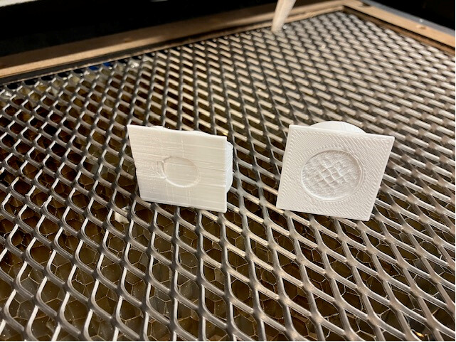
CUTTING TEST
I performed the same cutting test on 2.5mm birch ply at 15mA and 10mm/s with air assist which works well (other than the drag chain). The first cut was one pass using my 50mm tool from the material to the underside of the head and it just about cut through. I had seen a post from Ned, where he sets the height within the material, and when I did this, it cut cleanly through. I am going to test at different heights to fix the ideal height and make a new tool. On a roll I tried 3mm MDF with 2 passes and it cut maybe 2.5mm. My local hardware store has 2mm MDF and it was on the way to cutting through with 2 passes.
Thanks to all for your assistance and in advance for reviewing this update. Any further questions or comments would be welcome.
One other test that can tell you about the perpendicularism (word?) of the beam through the objective lens (head).
Put a target on the bed held down so that it will not move at the correct focal length.
Fire the laser
Lower the bed and fire again without moving the target.
If the beam is moving through the head perpendicular to the surface the two spots on the target should be on top of each other. If they are displaced the beam is not perpendicular to the objective lens.
Note if you do not have a moveable bed you may have to rig up spacers that you can remove to change the distance from the head to the target. In this case, make sure that the position of the target relative to the head does not change as you remove spacers. You can do this with a jig that ensures the spacers are always located in the same spot.
How I fixed that algae issue on neck of laser tube.
I dropped 2 ounces of Clorox bleach and a spoon of baking soda. In 2 hours all junk was gone. 2 years have passed and laser tube is fine. Hope it helps. ^¡^
1 Like
Apologies for my tardy response but unfortunately your notification had dropped into junk.
Thanks for the advice and I will give it a try as yes I do have a moveable bed.
I did a height calibration of my bed and noted that one full turn of the screw is around 1.5mm so my process is to use my tool to set 50mm from the underside of the head to the target (assumes it is around 0.8mm from the underside of the head to the lens) and then turn it 1 or 2 turns up depending on the thickness of the target to the focus is on the middle of the target. As a rule of thumb this seems to work as a rule of thumb.
I understood my mistake from day 1 one using antifreeze but I had seen a YouTube video on using glycol. Flushing the tube, changing the water and introducing algaecide is my next job and I take your point on the possible impact. Although I have read the excellent site article on cooling, using 4L of ice in ice cream tubs only reduces the temp by around 3C and so I am concerned that this might also be impacting on the laser’s performance. I will create a separate post on this subject which is likely to be my biggest challenge going forward particularly in this hot spell.
Many thanks. Do you mean that you maintain the bleach and baking soda in the water mix or you used it to flush the tube? I am about to flush the tube in the next few days.
Don’t fire the laser with bleach or baking soda in the water.
1 Like
I thought I would complete this post with a final update. I fixed the drag chain problem as the beam was partially impacting the chain at the home point and sometimes dragging the pullies out of the eccentric cams. I finally flushed the tube and to my relief it does look like it was debris in the neck as it flushed it out without a problem. I have now refilled the reservoir with clean distilled water and algaecide. I then re-checked the mirror alignment, and it is still very close at all four corners. I also checked the perpendicularism which looks fine. This left me one final problem in that I simply could not get the water temperature much under 20C, so I have posted a new topic on how I have resolved this problem. As it is I can now cut 3mm MDF as per the original problem, 3mm Ply and 4mm acrylic by raising the table from 50mm by half the thickness of the material as one turn on the table is around 1mm. This seems to work well so I am good to go. By carrying out my cutting tests of power, speed, in time these will be an indicator of the tube beginning to fail. In this regard I went through 3 diode laser heads. I presume this is the case where, in the first instance, I would increase the current to get the same cutting performance, but I do hope this is a while off yet.
3 Likes
If this problem is solved can you mark it as such, please?
1 Like