Hey all! New to the forums. Just got a k40 and decided to do a complete rebuild. I pretty much gutted the enclosure and am in the process of adding a lot of the recommended safety features, such as interlocks, water flow shutoff, etc. I’m fairly new to this type of stuff (lasers and electrical circuits). I know enough to get by, but otherwise a noob. I understand the voltage of the laser is dangerous and that I should be careful.
I bought the laser used off Marketplace and it has an upgraded Monport board so it is compatible with Lightburn. As a result, there were a lot of unused cables in the enclosure, which I’ve removed. The guy I bought it from said one side effect of the upgraded board was none of the buttons on control panel work, except the on/off switch. It seems like this is expected, and all control is done via Lightburn. I didn’t know if it was possible to wire things up so they’d function in addition to the control via the board, or not. If not, I wondered about removing them. Any tips or suggestions here?
Can someone provide a brief, real world example (or point me to a link) of what some of these might be used for? Items 1-13 are fairly obvious, but I’m not sure what 14-26 would be used for. I’m most interested in the PWM output signals and the temp controller signals and what I might use them for.
Sorry if these questions are basic. I’m just trying to learn as I reassemble my k40 and see if there are other modifications I should make.
Yesterday, I discovered my k40 has the plastic washers which I replaced and I had to remove paint from the chassis to ensure a proper ground as noted in the Light and Electricity page.
Thanks again
Probably the PWM signals are all controlled from the same pins, and follow spindle or laser control depending on the $32 setting.
20-23 might be connected to the enable signal for those axes if you are using external drivers but it’s not clear to me why. They do have four-pin headers in the middle (not labelled) for external stepper drivers.
I wish Monport had engaged here instead of spamming us so that we could reasonably just ask them.
Thanks! Appreciate the insight. For now, I think I’m going to add some of the easier safety additions, like interlocks and the water flow sensor and then reassemble.
It looks pretty much like most of the 328p processors based control boards.
Agree here… I’ve run one of my grbl boards to the stepper drivers in my China Blue… so people do use them… I had to remove the driver plugins on my board. The signals were not externally available.
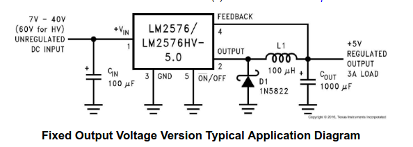
The two large ic’s on the left are power regulators… I suspect 5V and 12V as a guess. The output voltage of these are determined at manufacture.
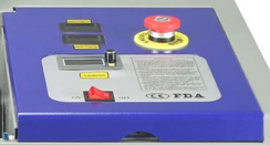
Is this your console? If your console knob and power switch is working, what part of this isn’t working? The only other switch I see is the emergency switch.
There is three pwm outputs, 14, 15 and 16. I’d guess they all source from the pwm output of the 328p.
It just seems to be what type of signal you need… A spindle might require 24V pwm or 12V pwm depending on the motor.
I think all of timers in the 328p are used for grbl so there isn’t any left for custom applications.
The lps (laser power supply) can have over 30kV on it’s output. If you steer clear of it’s connections to the tube, it won’t be an issue… you are using a dc excited tube, so it has to have a high voltage.