Yes the gantry moves in x-y, for example i’ve been sending a star shape vector to the K40, and when I’ve chosen vector cut the head outlines the star perfectly just without the laser firing.
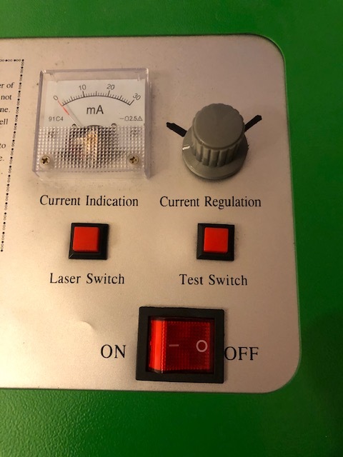
Ok, turn the laser switch to on,
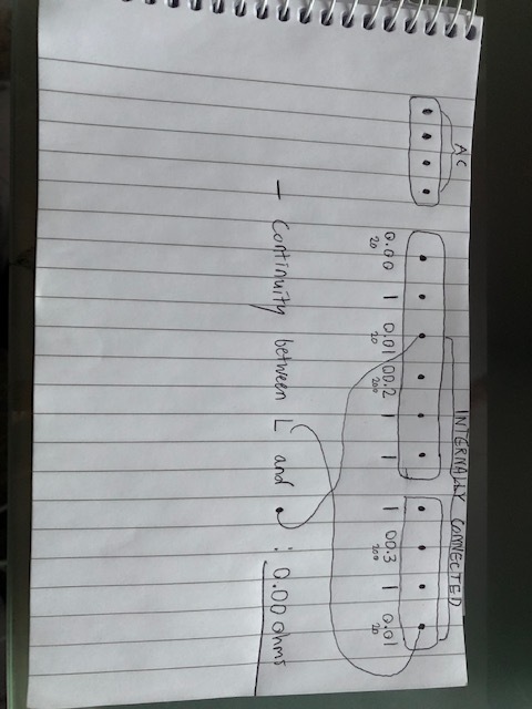
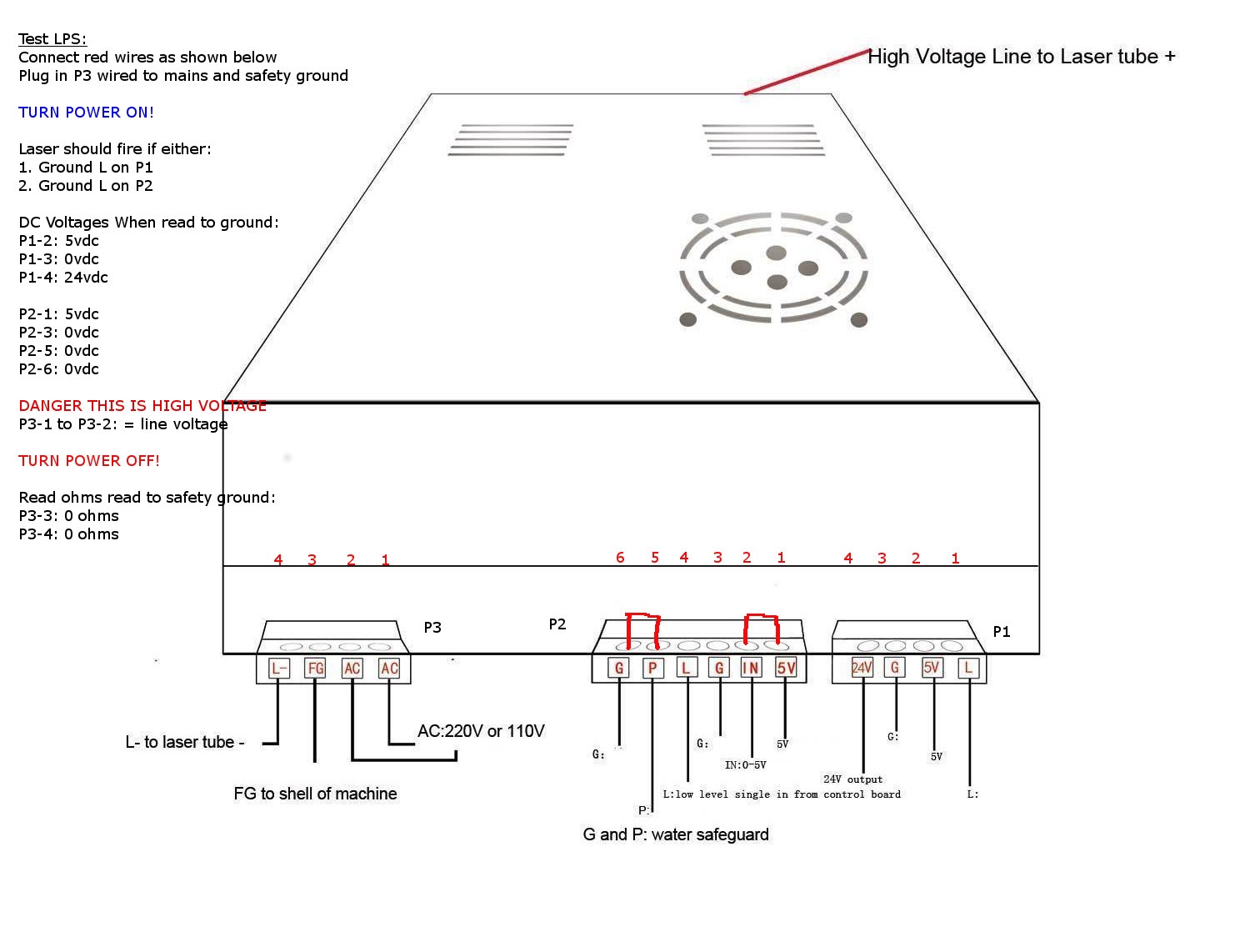
With the DVM on DC volts document the voltage on each pin of the 6 pin and right hand 4 pin connectors relative to the ground pin.
Do not measure the left-most connector which is AC.
Then turn off all power and unplug the machine.
Then unplug the two right hand connectors on the LPS. A 6 pin and a 4 pin.
Measure continuity [ohms] between the L pin [far right-hand pin] on the 4pin connector.
and…
The 3rd pin from the left on the 6 pin connector.
You will note in the photo of the connector definitions I provided in an earlier post that these two pins are supposed to be connected internally.
We are verifying that they are.
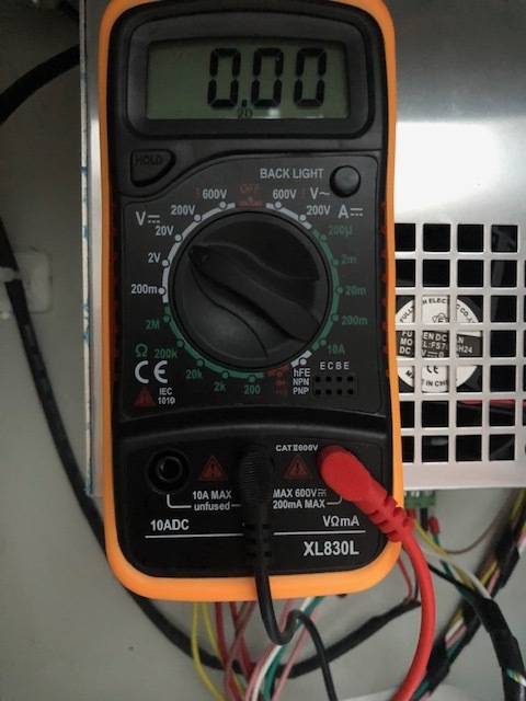
This does not make sense? These should be 0-5v levels for all but the 24V output? Usually when a meter shows 1 it is maxed out.
What are you using for ground? The ground on P1 or P2?
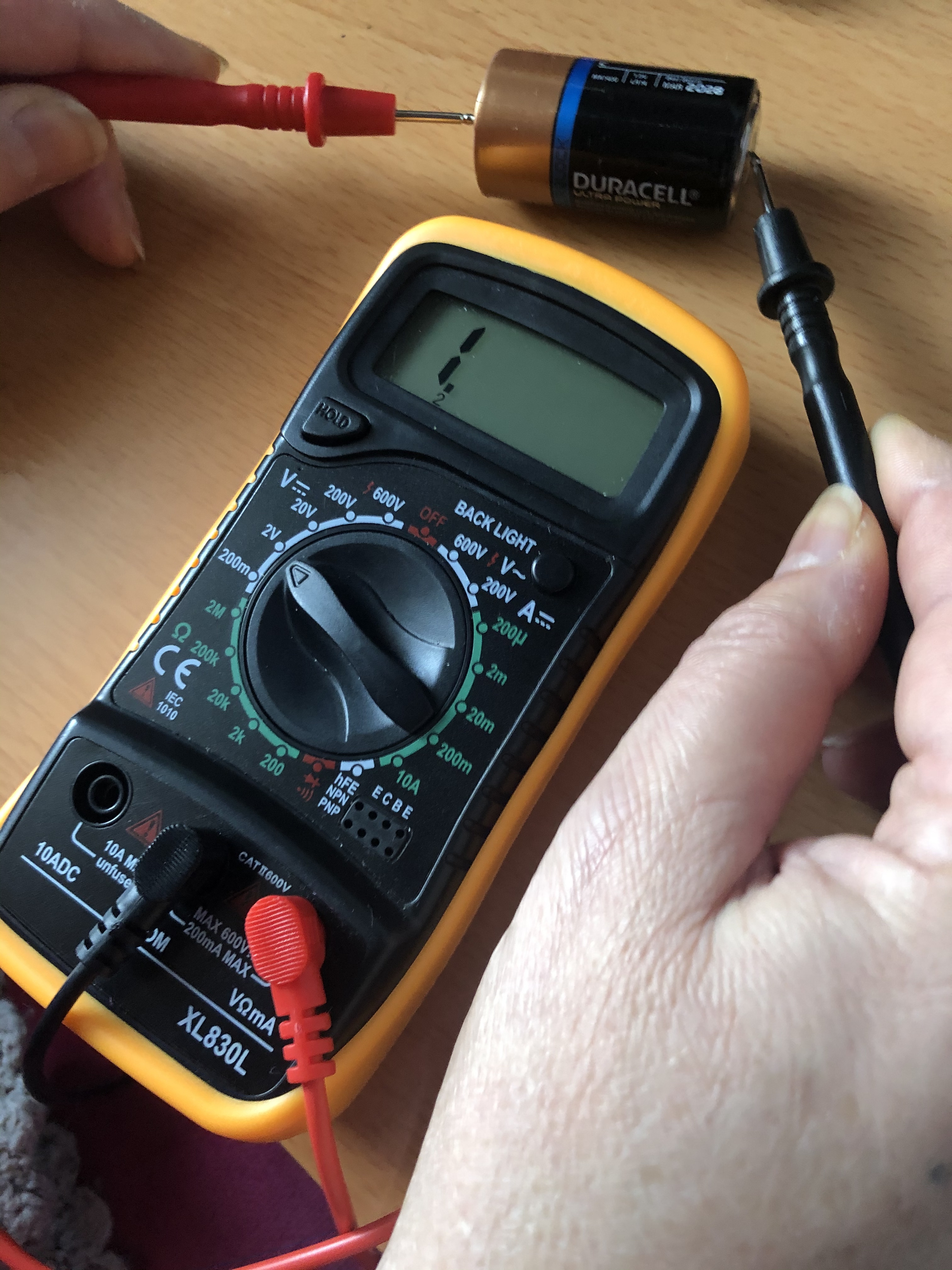
Can you measure a 1.5 volt battery with that meter?
Turn your POT to max and then see if the laser fires with the Laser Switch = ON and the Test Switch button.
It maxes out and shows “1” when I put the DVM down to 2V.
Just turned the POT to max and noticed something strange, it doesn’t seem to fire at all at max, seems fine from 0%-50%, but then the strength of the laser seems to decline from 50%-100% where is doesn’t seem to fire (was making dots on some wood to judge this). I tried to attach a video but it was too large - the mA dial moving all the way from left to right at lower power from the POT, but moving less as I increase the power - seems things could be the wrong way round here?
To stay in sync. Reference these #'s in your answer please:
The laser now fires during a job with the pot adjusted to 50%.
Unlike before we have the laser firing (albeit at 50% pot position)?
It seems the power is lowest at max pot position and highest at min position of the pot?
Something still wacky with the meter readings:
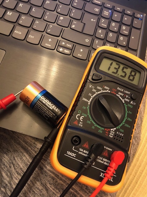
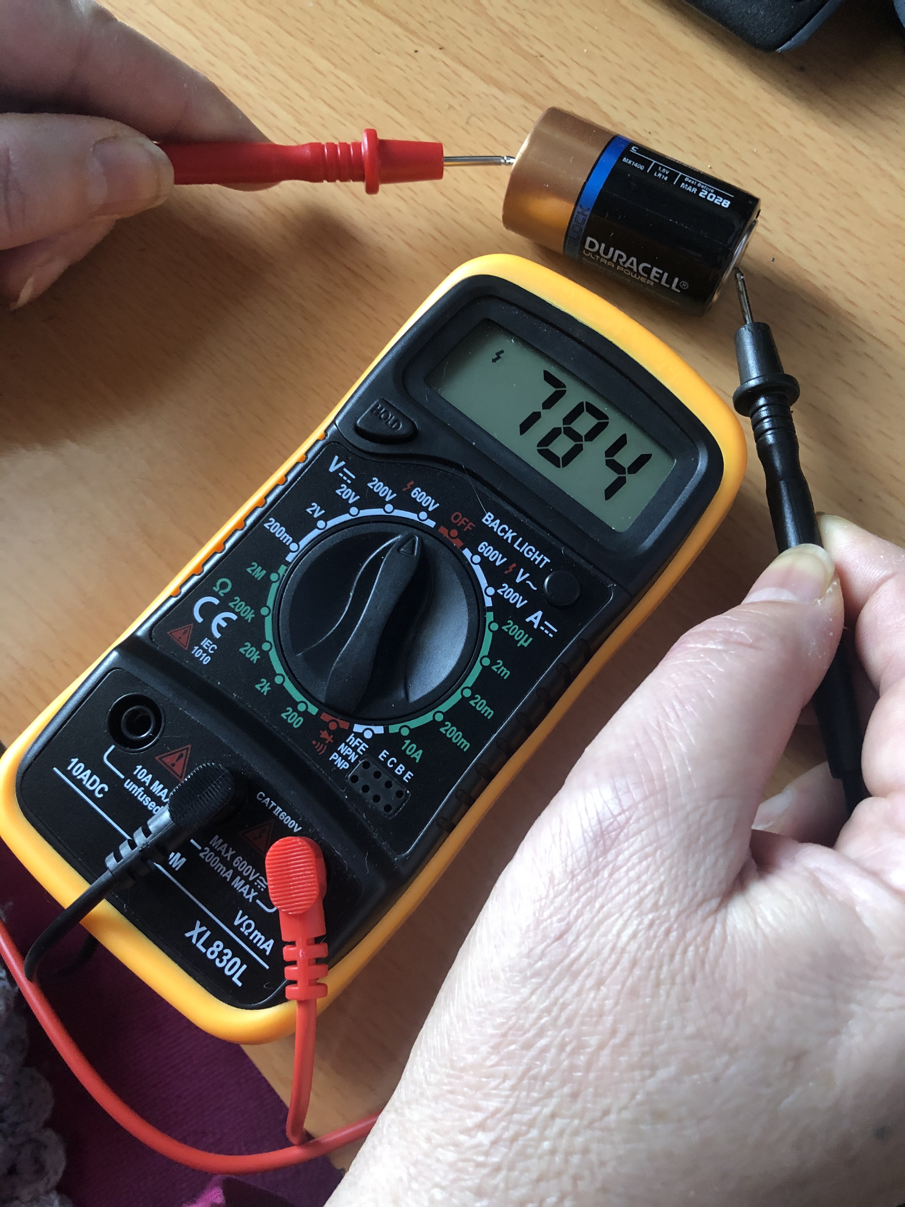
Across the battery and on 20V scale the voltage reads 13.58 volts. Perhaps the battery is 1.38V and we have some scaling problem?
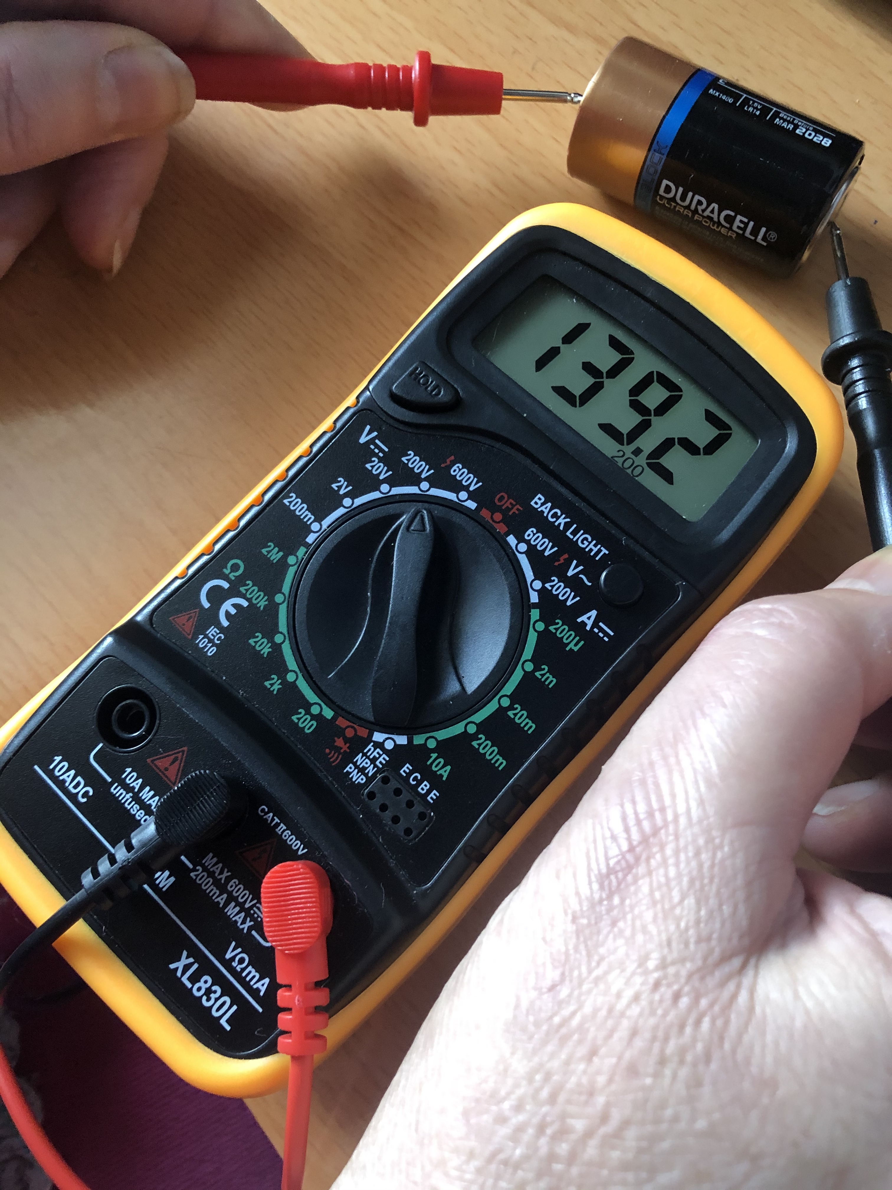
Across the battery and on 2V scale the voltage reads 1 (which usually means overrange and voltage is >2V vs 1.5V ???)
I looked at the manual for that meter and nothing seemed weird!
We need to get good readings on the battery with that meter before we can trust the next tests.
Next test if the answer to #1&2 are yes and we get the meter working right.
Put meter on DC volts and measure the potential at the IN pin (P2-2) relative to the ground pin (P2-3).
While turning the pot from extreme left to extreme right the voltage should change from 0-5V on IN. After we figure out how to measure with that meter we should do this?
With machine power off:
4. What is the resistance between the P3-FG and P2-G?
5. What is the resistance between ground on the controller and P2-G?
No. The laser still doesn’t fire on a job with the pot adjusted to 50%. I should have mentioned in my previous reply that I was referring to using the test laser button.
The laser only fires when I press the outer test button and the LPS test button.
Yes. after ~ 80% however it doesn’t seem to fire at all (wasn’t making a dot after a long time holding test).
Meter readings
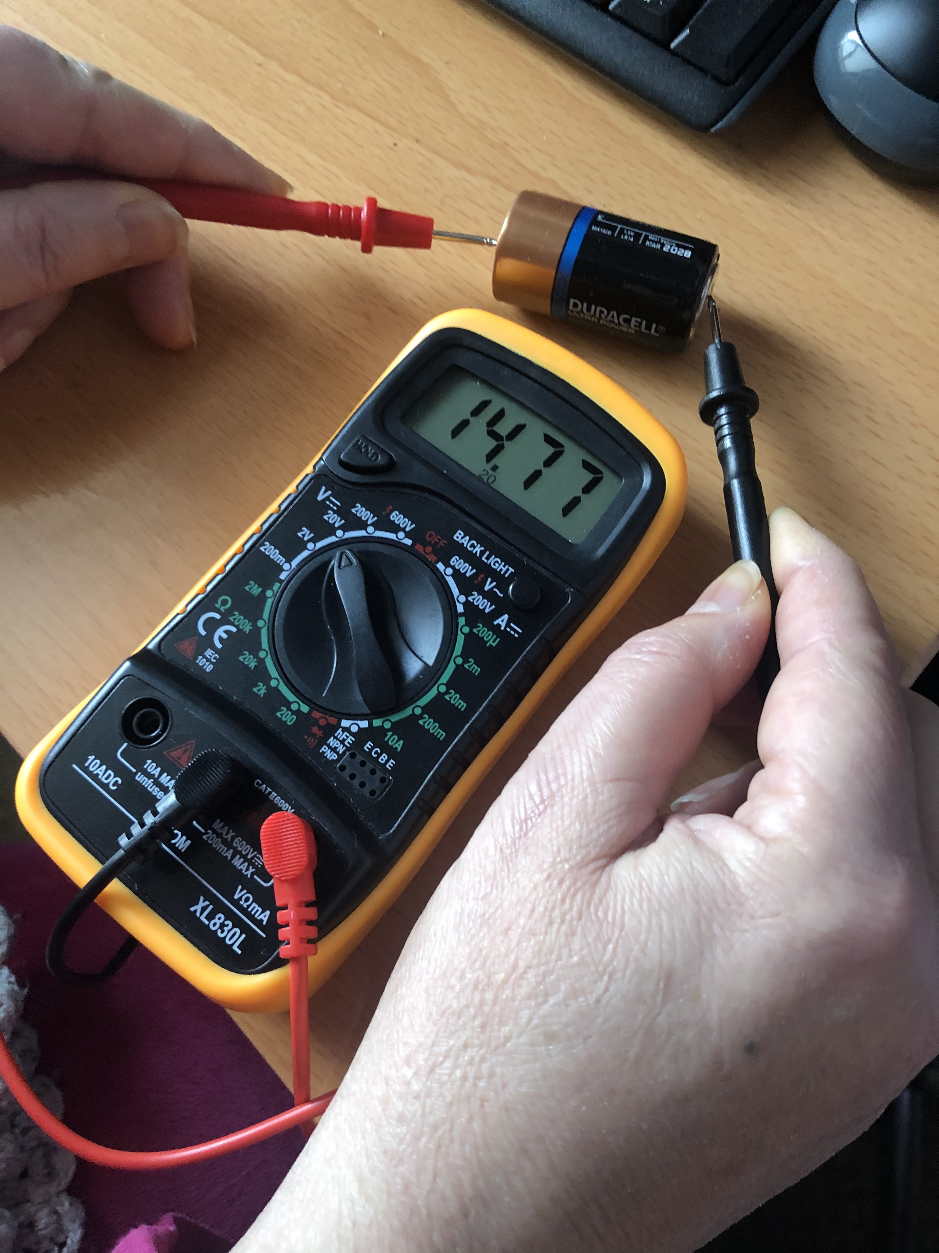
I suspected a scaling problem, as 2 other equivalent batteries read 13.98 & 14.21 … maybe the decimal point should go left 1.
Yes the voltage reads 1 across the battery on and on 2v scale, strange I know, when I push it up to through the scales the assortment of numbers stay similar while decimal point moves right, so maybe just weird scaling?
Sorry for being redundant but I must have missed something
The laser fires when:
The laser switch is on and the pot is in the middle position and the test switch is pushed.
The laser does not fire when:
The laser switch is on, the pot is in the middle and a job is run.
Tests show:
Pin P1-1 has 0 ohms when measured to P2-4.
When P1-1 is touched to ground the laser does not fire!
Ok… here is what makes your head hurt!
Since P1-1 is connected to P2-4
and;
the “Test switch” is connected to P2-4 [the controllers signal wire and the test switch are connected together]
and;
the Test switch" will fire the laser which means that P1-1 must go to ground when the Test Switch is pushed.
Yet;
connecting P1-1 to ground does not fire the laser
Usually when something is this wacky I start looking for ground problems.
Check this:
Is the ground in the LPS connected to the ground on the controller. (i.e. 0 ohms)?
Make sure you measure from a G pin on the LPS to a ground point on the actual controller PCB. Do not trust the PCB connectors.
Right, I get the logic. Strange how connecting P1-1 to ground doesn’t fire the laser when it does go to ground.
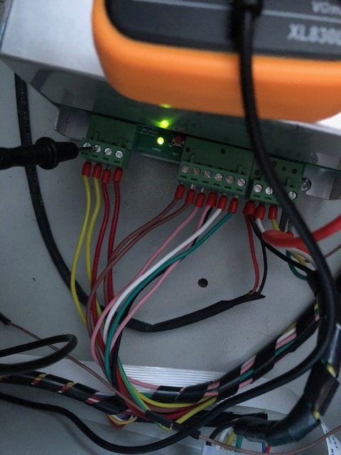
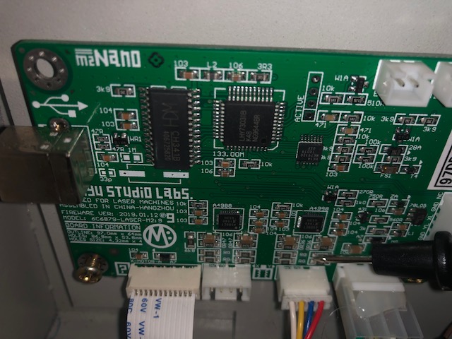
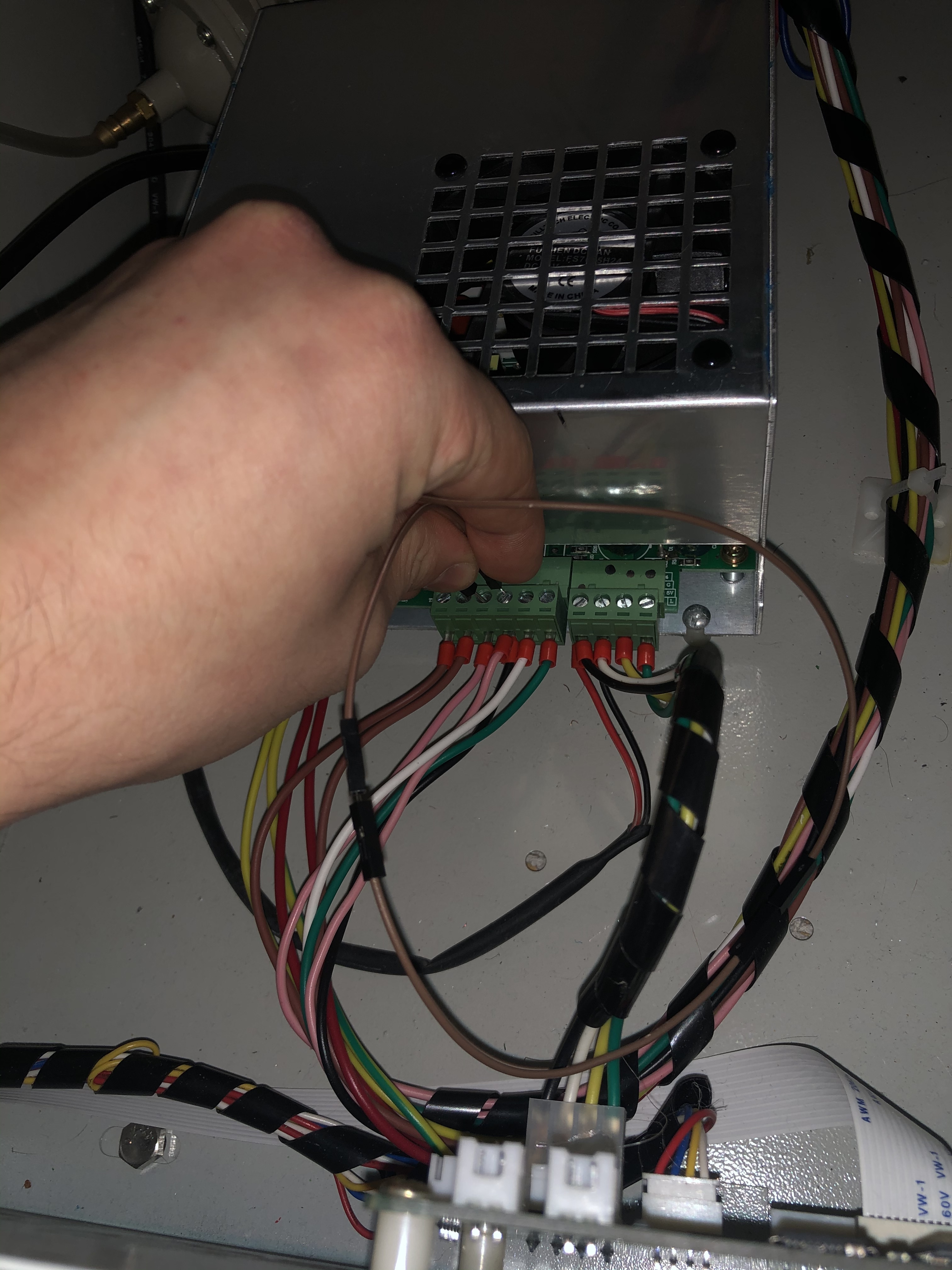
I measured from both P2-3 and P1-3 to what I think were ground points on the PCB … are these the small metal bumpy bits? My DVM showed 0 ohms. (see pic)
all I could see online were some people’s DC readings showing double, I flicked around with the different settings for my DVM and the readings are still weird for batteries, I could order a more expensive one on prime for next day delivery (although the relatively cheap one I have has thousands of good reviews)
I’ll go back and check through the steps again to see if there’s a wrong assumption somewhere
Doesn’t look good
I have a few pretty inexpensive ones and I am very happy with them.
While you are getting the meter thing settled lets try this test:
Laser Switch ON
With a jumper momentarily connect P2-4 to P2-3 and verify the laser fires
If it does then with the same jumper momentarily connect P2-3 to P1-1 verify it does NOT fire