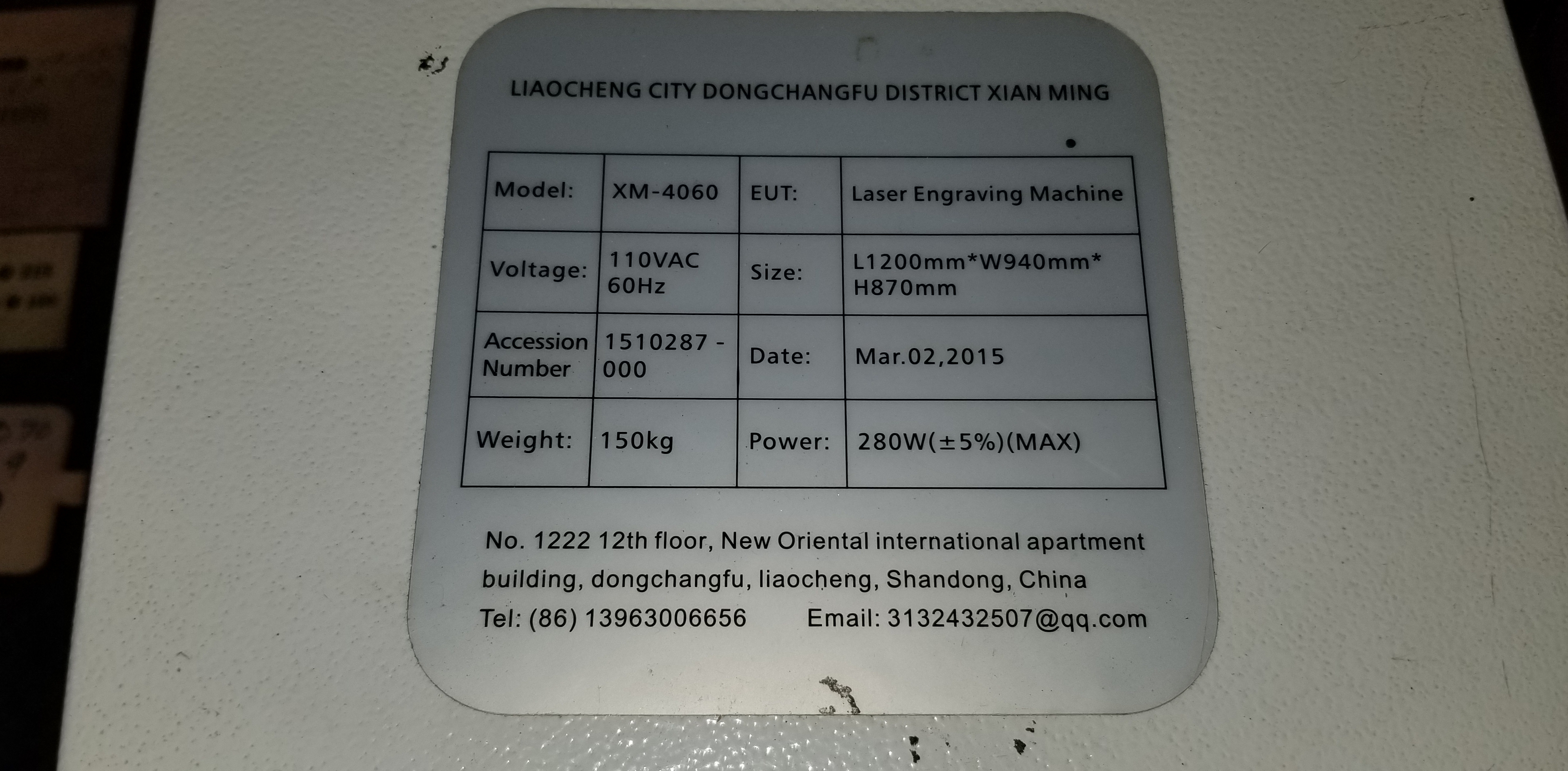
My K40 laser (XM-4060) has stopped firing when I run a job. It moves like its cutting but doesn’t fire.
It Does fire when I push the panel test button and it Does fire when I push the PSU test button.
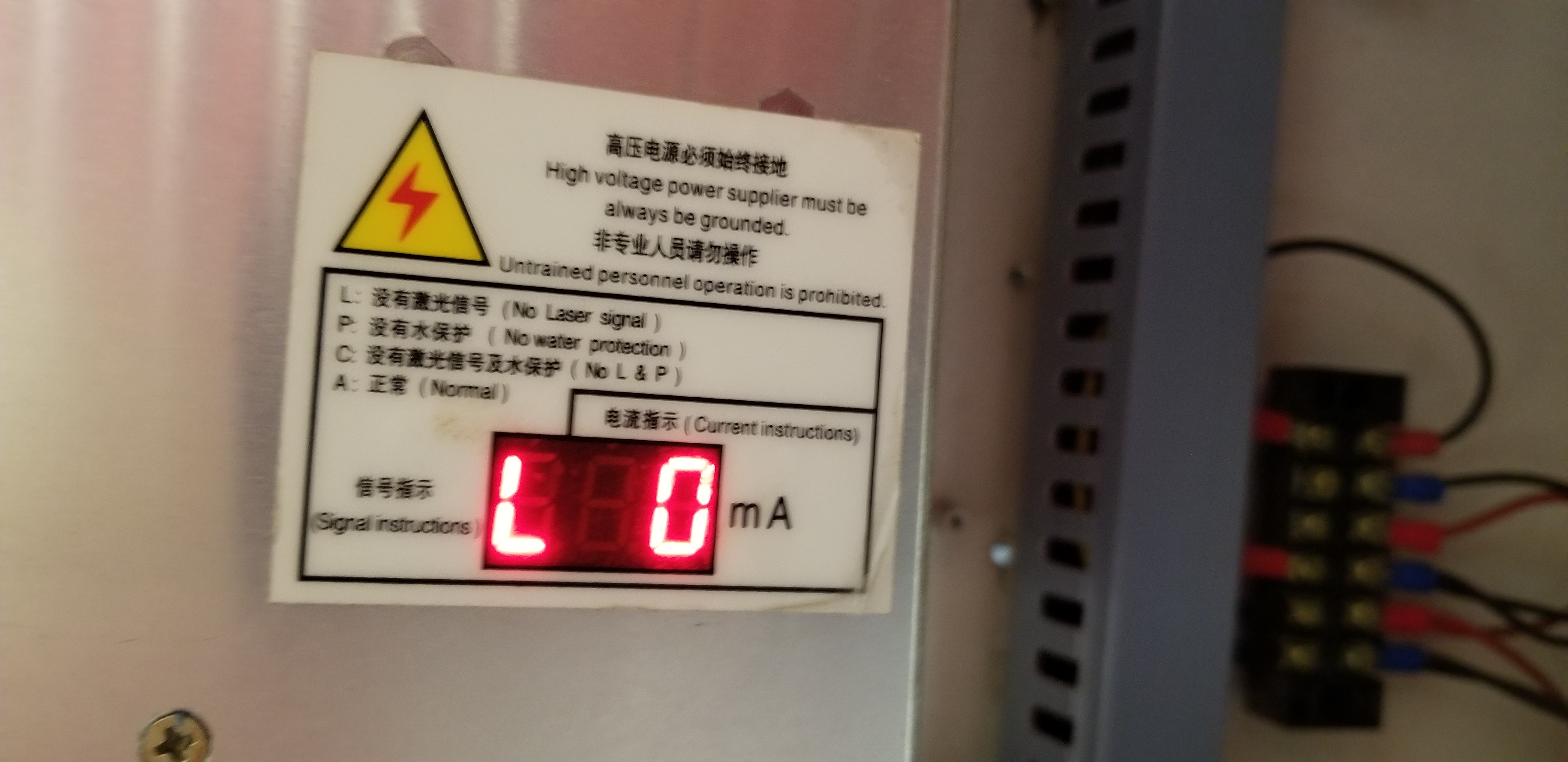
The PSU message states “L” which says L= No Laser Signal
I have replace the controller board from a B-1 to a M2nano. No change still the same error. The machine has worked perfect the past couple years. It was died by the laser getting dimmer and dimmer and dimmer until no more light was being produced. It has a brand new bulb in it. And when I push test it fires up and glows normally. It was used 3 times before it did this and I dont think its the bulb since it can still cut with test.
Again… All test buttons make it fire at full power and I can just hold the button down and run a job and it will cut out the plywood…
Can someone please shoot me thoughts on what to replace to try. It would be greatly apprecaited… I have been dead in the water for 3 weeks and my company has come to a halt on production. Wondering if its a bad power supply??? (is that possible since it still fires?)
I have done the following…
The machine homes and drives and works normal. Just wont fire when cutting a job sent by the laptop.
It has a Water Flow Switch. I have unplugged everything in P and GRND and made a cable that goes in P and the other end in GRND. Still says L and wont cut during a job.
I have confirmed voltage in the controller board cable does have 5v and 36v and the ground in the cable works
The fan on the PSU works, the PSU red light turns on when either test button is fired and it does change to “A” Meaning Normal when either test button is fired.
I have tried a new USB cable and tried a different port on the Laptop. Still “L”
I have ground off the paint where the Ground goes to the screw in the back of the laser cutter. And it appears all have a ground.
I have unscrewed all cables out of the PSU and plugged them back in and tightened them down
I put a new laser bulb in a month ago and have made a couple hours worth of cuts with it. It does fire and light up when testing. Again it does cut out my 1/4 plywood if I hold test down the entire time. There is NO sparking or anything weird with the bulb and no cracks. And no pinches in the water cooloer hoses.
I have blown out all components with the air compressor. Again no change
I have tried another outlet. I tested the outlet and it does have a good ground.
I have NOT replaced the PSU, Waterflow Sensor, anything else other than the controller board.
If you could please list things to replace or try to get this up and going again… I greatly appreciate it.
Donkjr,
Greatly appreciate your reply.
This is an amazing forum and hope our discussion helps others in the future as this one is a bit of a head scratcher.
Answers:
Its a 100W XM-4060 large production laser cutter. Large K40 type.
The message “L” is posted on the Power Supply Unit (PSU) It has a diagram that states this message means: “No Laser Signal”. It does have the ability to give me an error code for Water protection… But at the moment, im not getting that… Just “L” no laser signal.
Laser Power Supply is stock, its model: MYJG100W
It does have a Water Flow Switch. I have attempted twice to by pass it. I cut both wires at the switch and twisted the wires and powered on the machine. Same error. I pulled all wires out of the PSU port P and GRND. I then made a jumper wire that went from the P to the Grnd on the Power Supply. Both still gave the L message.
Assuming DVM means Digital Voltage Meter, yes, I am familair with it. I have tested the grnds and the 5v and 36v that go to the Controller board. They all test fine.
My gut is telling me its the Power Supply, but before I plopped down a couple hundred bucks and waited a month… I thought it might be best to check with you guys.
I have gone through every wire and replaced the controller board. I emailed CloudRay and asked what they thought. They may be pushing for a sale, but he stated by what I described it sounded like a power supply issue to him.
Researching this k40 forum, I finally found an explanation very similar to my issue… If you agree with the advice stated… I think I need to check for a return signal from the main controller board… If I get a signal then BAM… Its a bad power supply… If I dont get a signal… Then I have a wiring or controller board issue.
I will test and update my results of what I find shortly.
Article Suggestion on another post to another member:
Next thing you should check is the signal to the power supply(from the mainboard) if the laser fires when you hit the test switch, but does not fire when cutting or engraving, the mainboard may not be sending the fire signal(or it may not be reaching the power supply) The circuit in question would be labeled with a “L” on the power supply(it may be labeled with a K+ on your power supply). This is the TTL input (active low, I believe) you should check this circuit with a meter or oscilloscope, when cutting or engraving, to see if there is a signal being sent from the mainboard.(should be 5v when the laser is not firing and should be less than 1v when firing) If you do have a signal, the power supply is the problem, if you do not have a signal, the mainboard or wiring is the problem.
You said earlier that if you hold down the test button while running a job it would cut properly…
1.right?
If yes then there is an intelligent signal coming from the controller! This suggests that the power supply is not enabled when a job is run but a signal can be seen from the controller.
In the scenario where you hold the test button the LPS and controller work…
2. right?
If so something is wrong with the control of the LPS while running a job.
Does the machine have a “laser switch” (enables the LPS) and a test button?
Please post a picture of the panel.
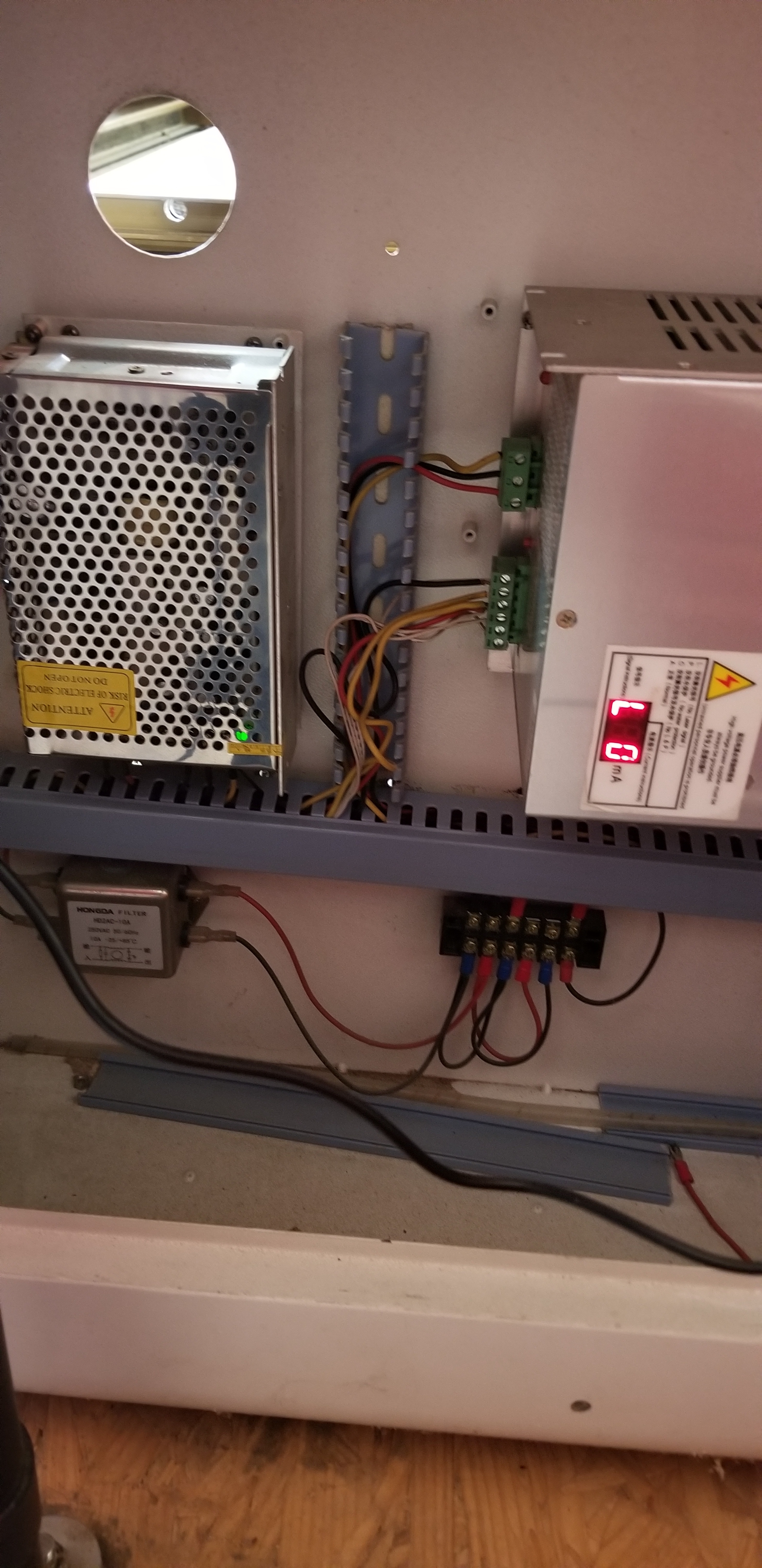
LPS wiring questions:
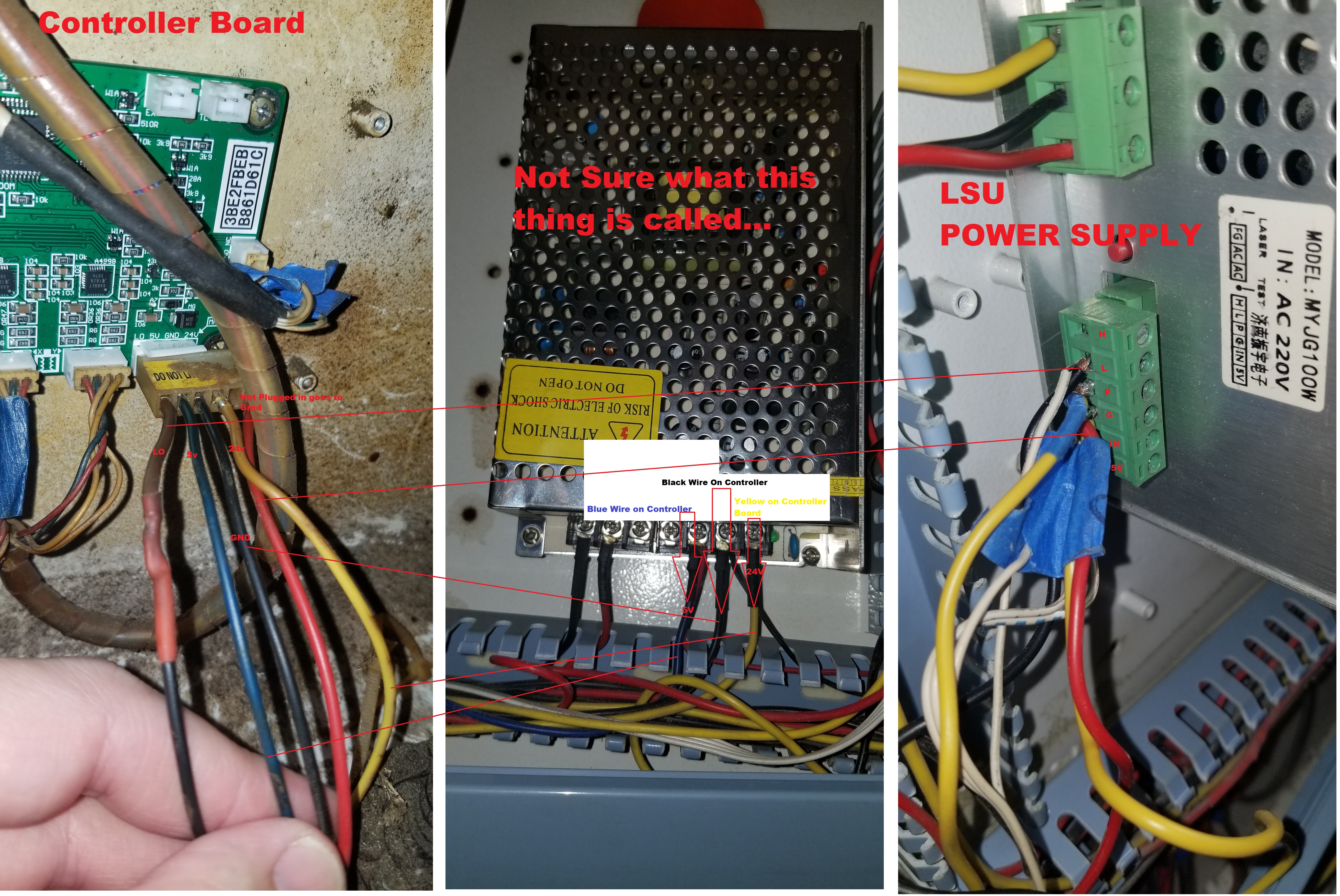
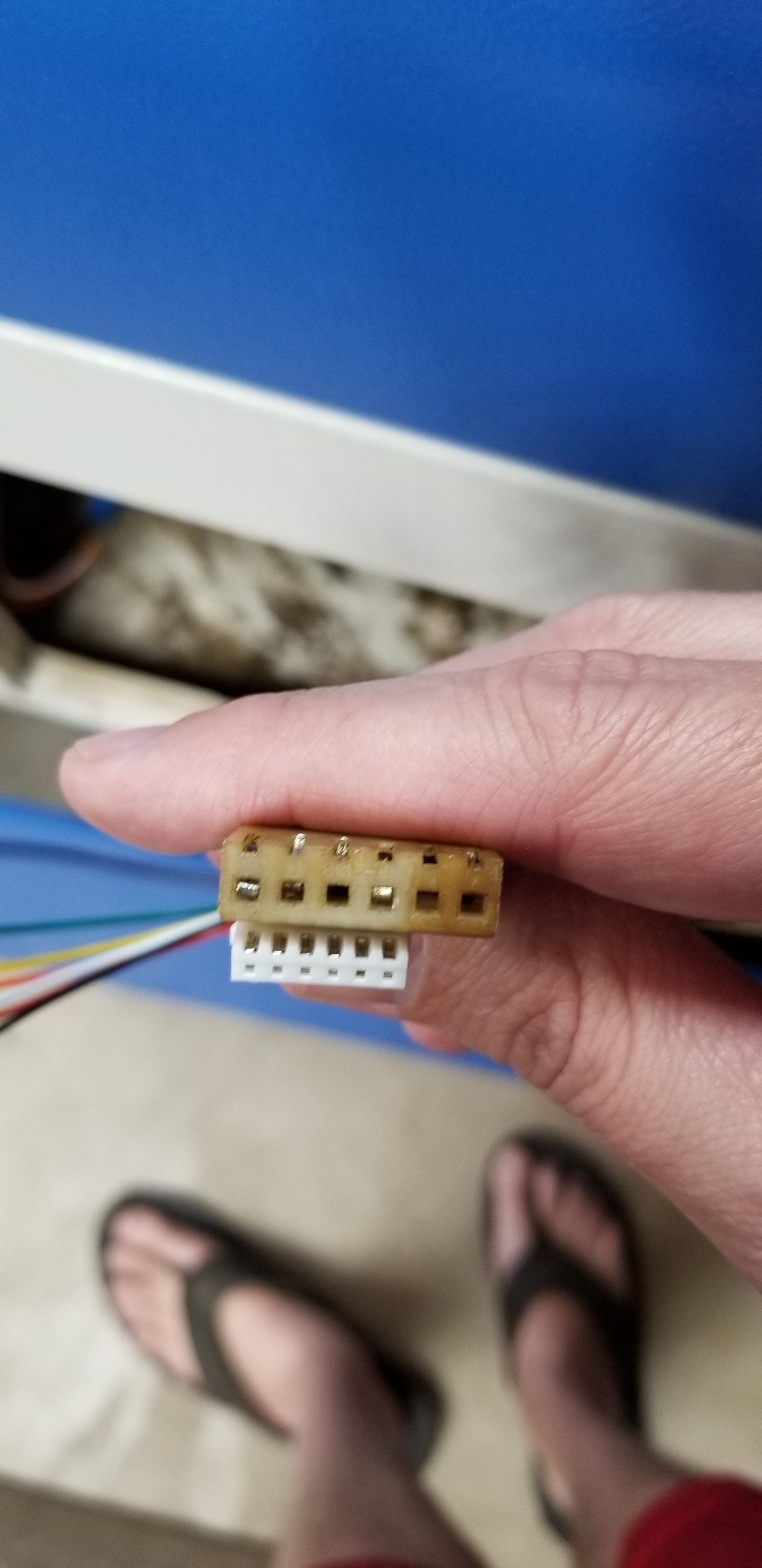
On the L pin [2cnd from the left] there is a black and wht/blk wire connected.
3. Where do they connect, I would expect only one wire on that pin.
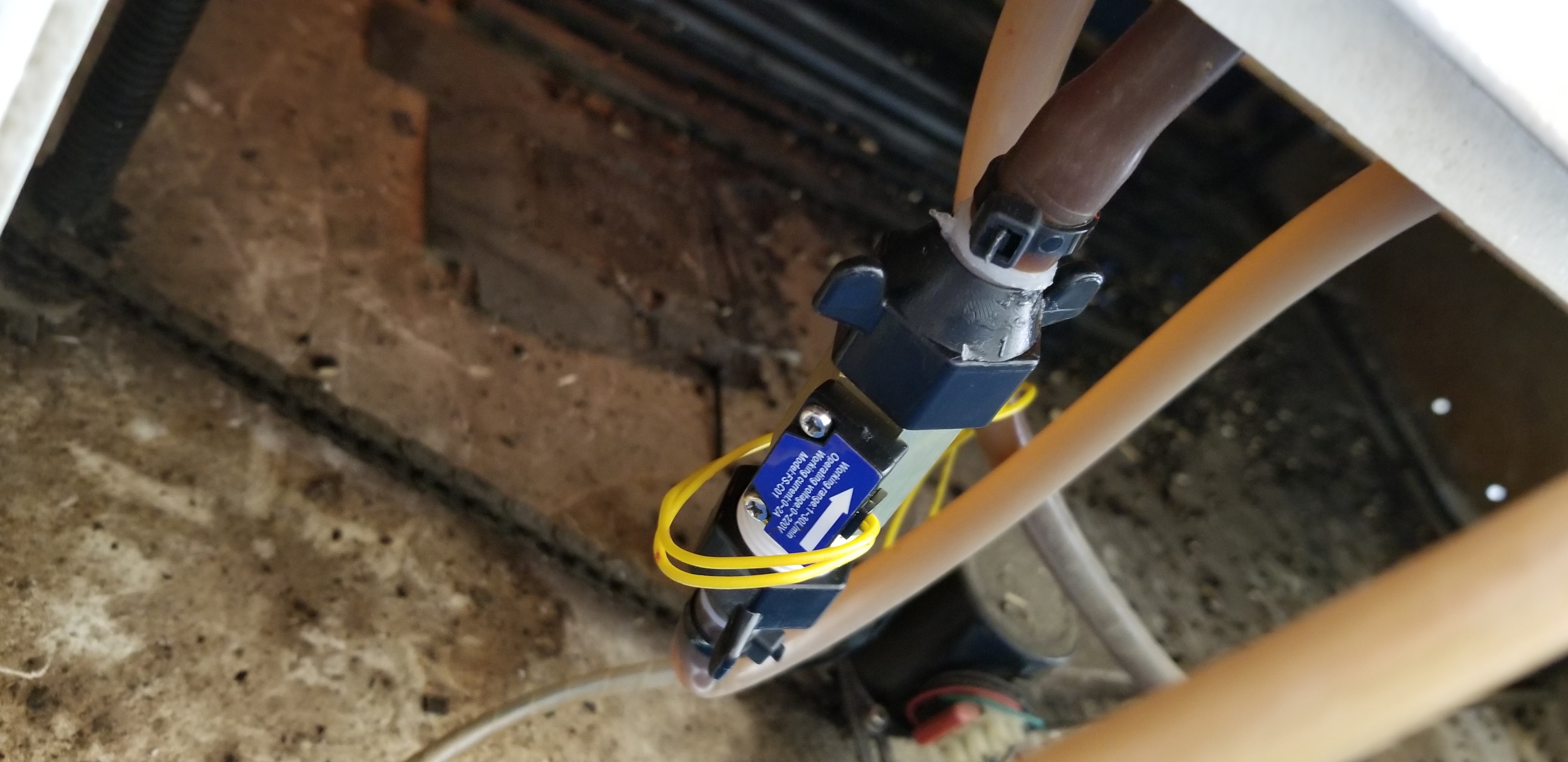
On the P & G pin there is a yellow wire. This is likely the interlock loop. However, the water flow switch has black wires??
4. Can you trace the yellow wires and tell me where they go?
5. Can you trace the water flow switches black wires and tell me where they go?
LPS measurements:
-Machine on, interlocks closed
-DVM on volts scale
-no job running
-laser enabled
-DVM plus lead on the P pin
-DVM minus lead on G pin
6. record the voltage value
Post picture of the meter with value
-Machine on, interlocks closed
-DVM on volts scale
-laser enabled
-DVM plus lead on the P pin
-DVM minus lead on G pin
Run a job
7. Record the voltage value
Post picture of the meter with value
You said earlier that if you hold down the test button while running a job it would cut properly… 1. right ? Correct. Holding either test button or LPS Test button will make it fire and hold the laser on if you hold either button
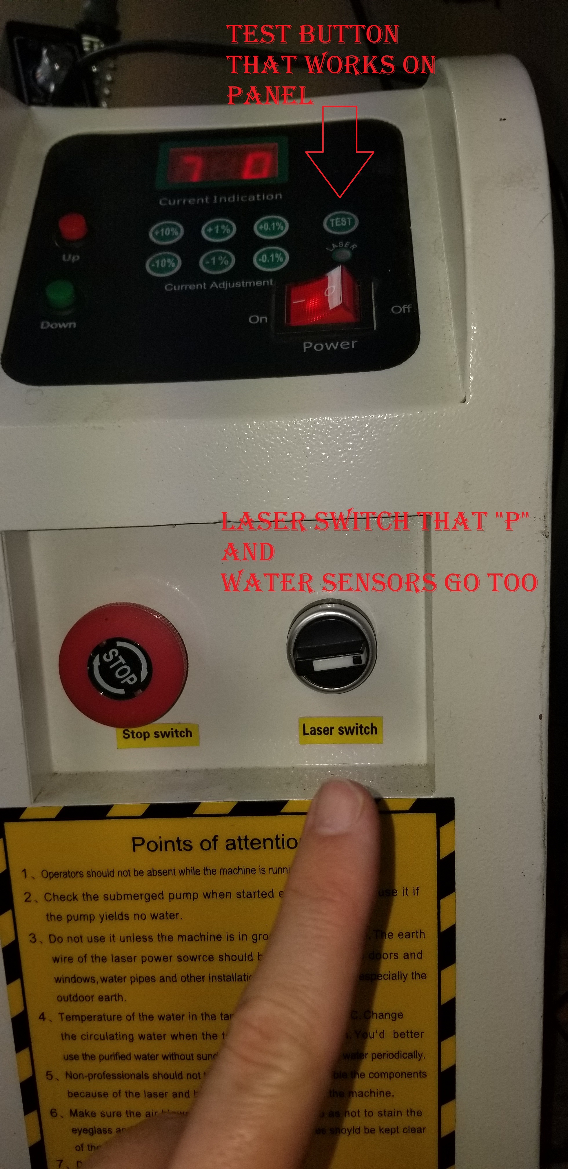
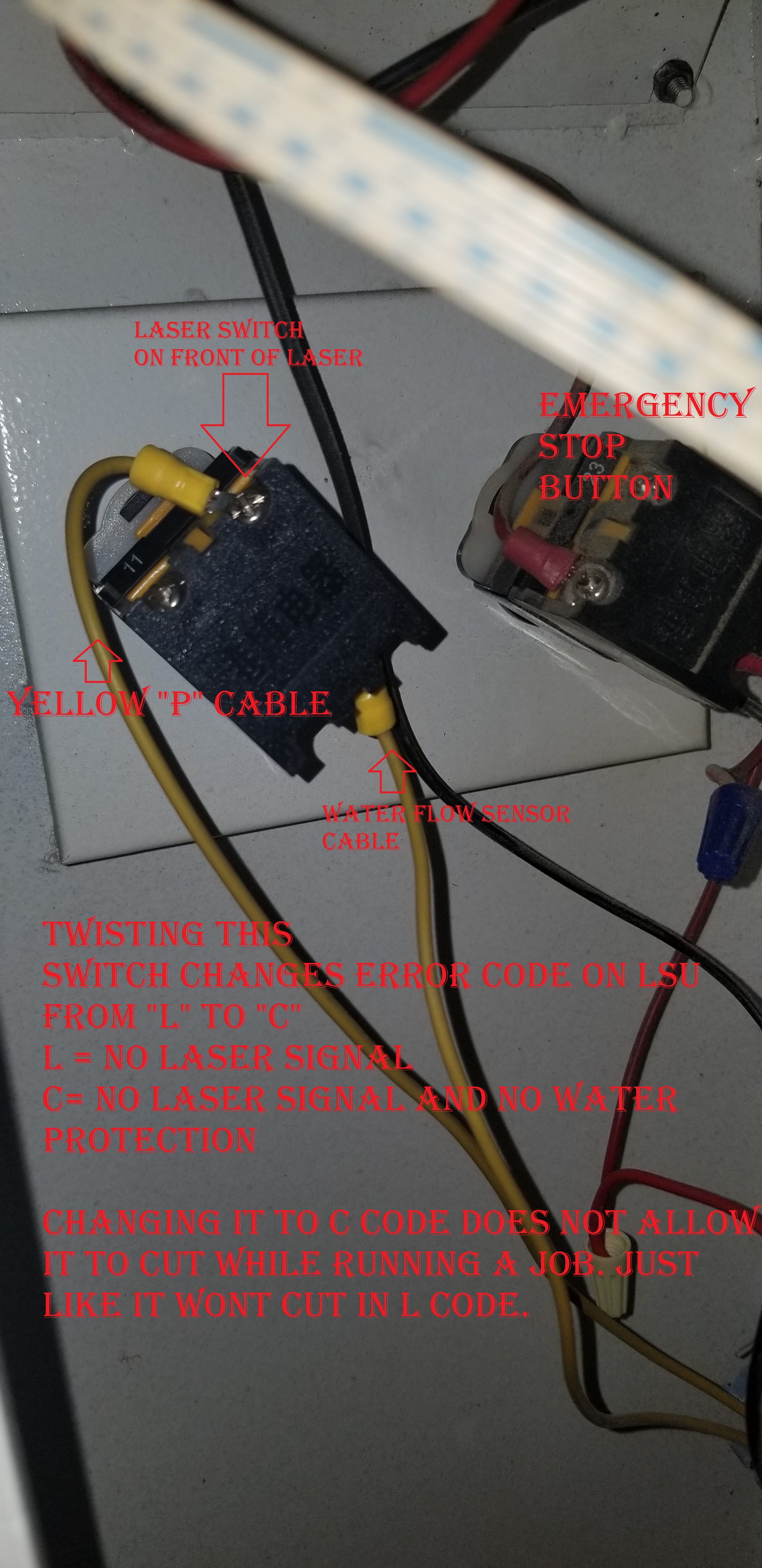
2. Does the machine have a “laser switch” (enables the LPS) and a test button? Please post a picture of the panel. Pictures posted. Test button on main outter panel as well as the LPS red button.
LPS wiring questions:
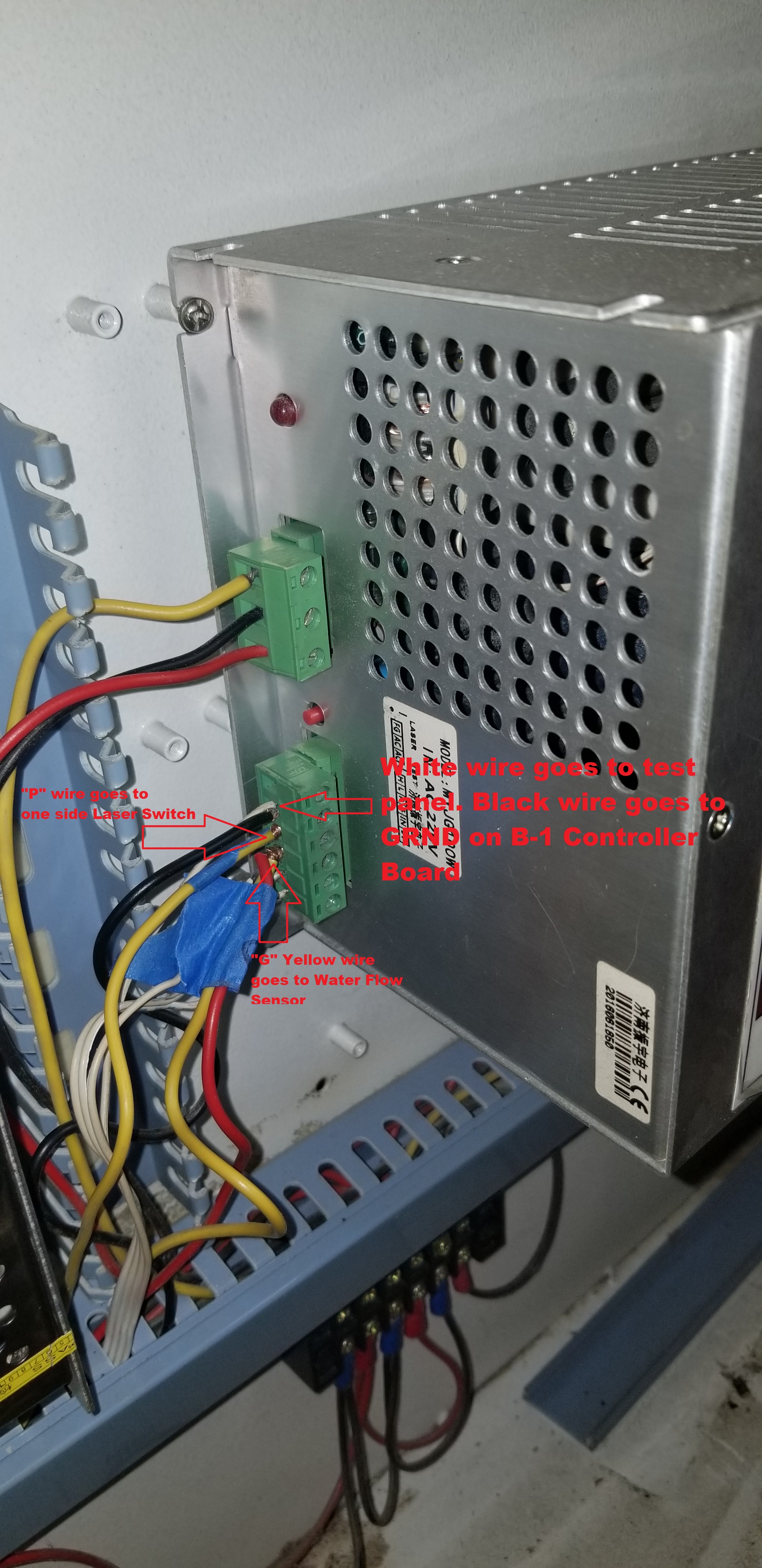
On the L pin [2cnd from the left] there is a black and wht/blk wire connected. 3. Where do they connect, I would expect only one wire on that pin. The White cable goes to the Outter control panel that has the test button on it. The black cable goes to GRND on the B-1 Controller board inside the laser cutter
On the P & G pin there is a yellow wire. This is likely the interlock loop. However, the water flow switch has black wires?? You are correct. after tracing the wires the Waterflow sensor wires start off black and then turn yellow.
4. Can you trace the yellow wires and tell me where they go? One water flow wire “yellow” goes straight to “G”. The other Water flow sensor wire “yellow” goes one side of a “Laser Switch” I have on the front of the laser cutter. The Yellow wire in the “P” goes to the other side of that “Laser Switch” (opposite side of the Yellow Water flow sensor wire)
LPS measurements:
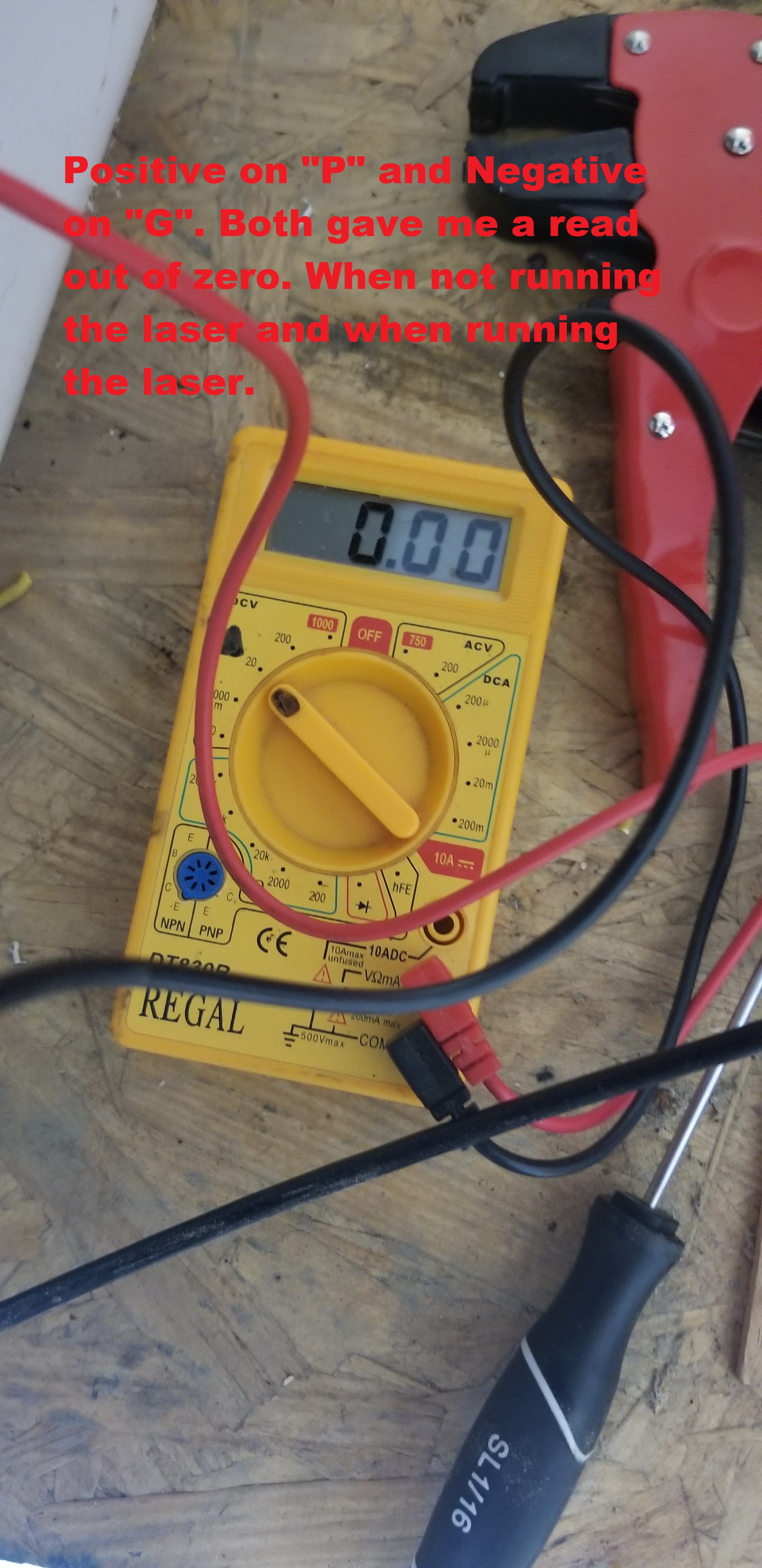
-Machine on, interlocks closed -DVM on volts scale -no job running -laser enabled -DVM plus lead on the P pin -DVM minus lead on G pin 6. record the voltage value Post picture of the meter with value I tried this multiple times… It would sit at 0. I would try it off the wires and on the screws themselves. Still zero. I soldered the wires for a possibly a better connection. Still zero.
-Machine on, interlocks closed -DVM on volts scale -laser enabled -DVM plus lead on the P pin -DVM minus lead on G pin Run a job 7. Record the voltage value Post picture of the meter with value Job running I still got zero. Everyone once and awhile it would hit 0.01 but never anything above that.
With all those results. Do you feel it sounds to be the waterflow sensor? If so… please tell me the best way to properly bypass it to see if a job would then cut. Or if your gut is saying its the LSU, then let me know and I will get a new one ordered. Look forward to your reply Don. And you have no idea how grateful I am to have you assisting.
Thank you very much for taking the time to help me. Brian
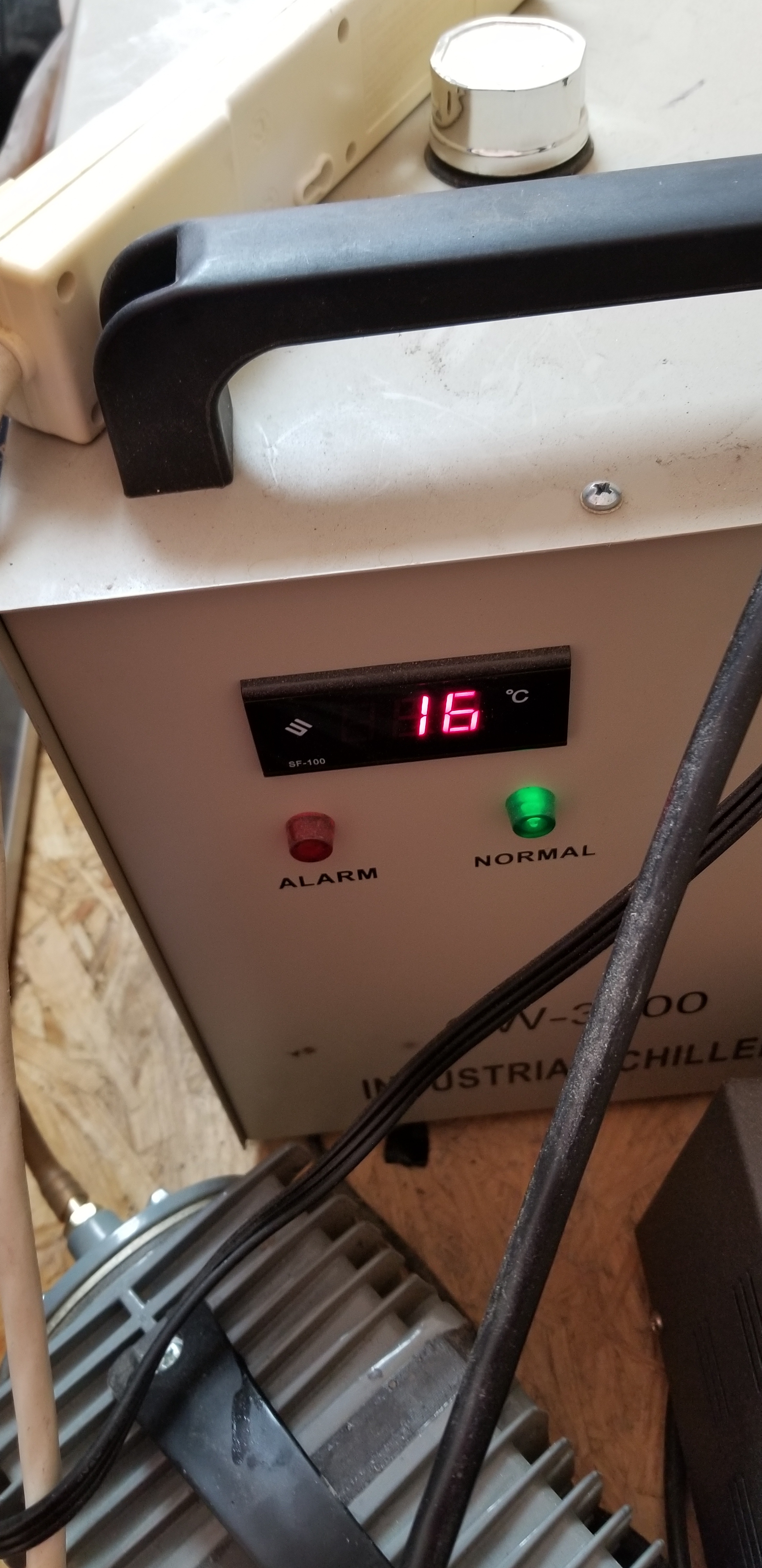
I came across a Youtube video discussing how to test a waterflow switch sensor. He instructed to cut both wires on the water flow sensor, Turn on your chiller, put Positive and Negative of your Multimeter on these 2 wires and watch for a current of some kind to register. My multimeter registered nothing. Just zero as the chiller ran water. The chiller gave a weird error LL. Again the multi meter does work…
If this test makes sense to you, and my result is zero… I would conclude I have a Waterflow Sensor issue and I am ordering a new one tonight.
Interested to hear your thoughts from all the evidence I provided.
As I digest the previous post let me answer this one. At this point, I do not think the water flow switch or the LPS are the culprit. However while I am answering the previous post you can check the switch as simplified below.
To be specific with terms, when the switch is disconnected from the circuit there will not be any current flowing in the switch as it does not have any power source. We want to test to see if the switch closes when water is flowing. When an ohmmeter is put across the leads of the sensor it should read short (0 ohms) when water flows and the switch closes and alternately it should read open (infinite ohms) when water is not flowing.
Ensure that your meter is set on ohms or continuity scale [continuity is sometimes denoted by a diode]. You can check this by shorting the leads together if the meter reads 0 ohms or beeps or both you are on the right scale.
Once you have verified you are on the correct scale disconnect the water flow switch and test across the leads of the switch while the water is running. It should read 0 ohms, beep or both.
To insure that we are measuring correctly post a picture of the meter when you take a measurement so I can see the selector dial and the display :).
BTW: when you are answering a question and have the edit window open you can mouse out of the edit window and highlight the question at its source. A small dialog will open above it with the words ["Quote] in it. Click on that box and the system will insert that question into your edit screen. This will save retyping
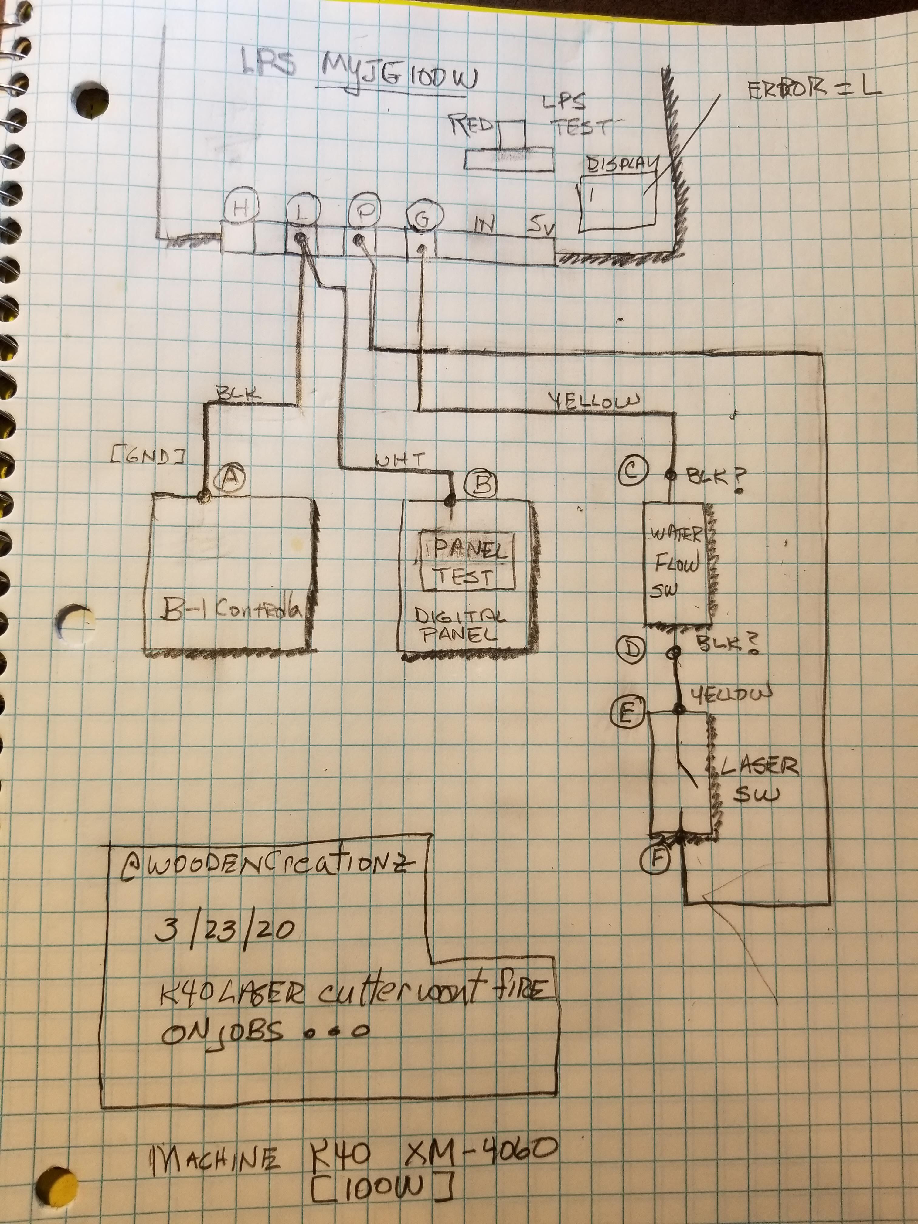
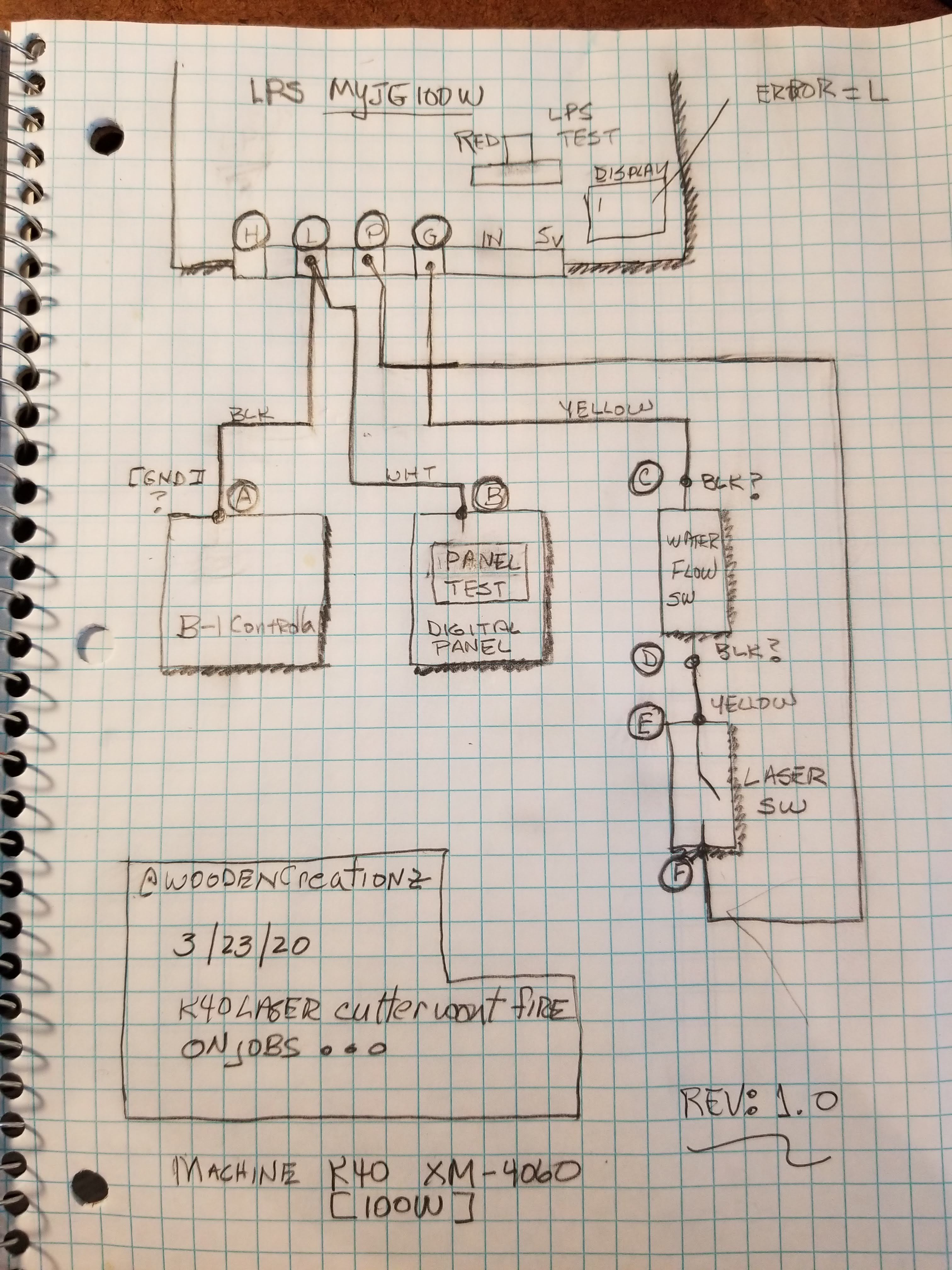
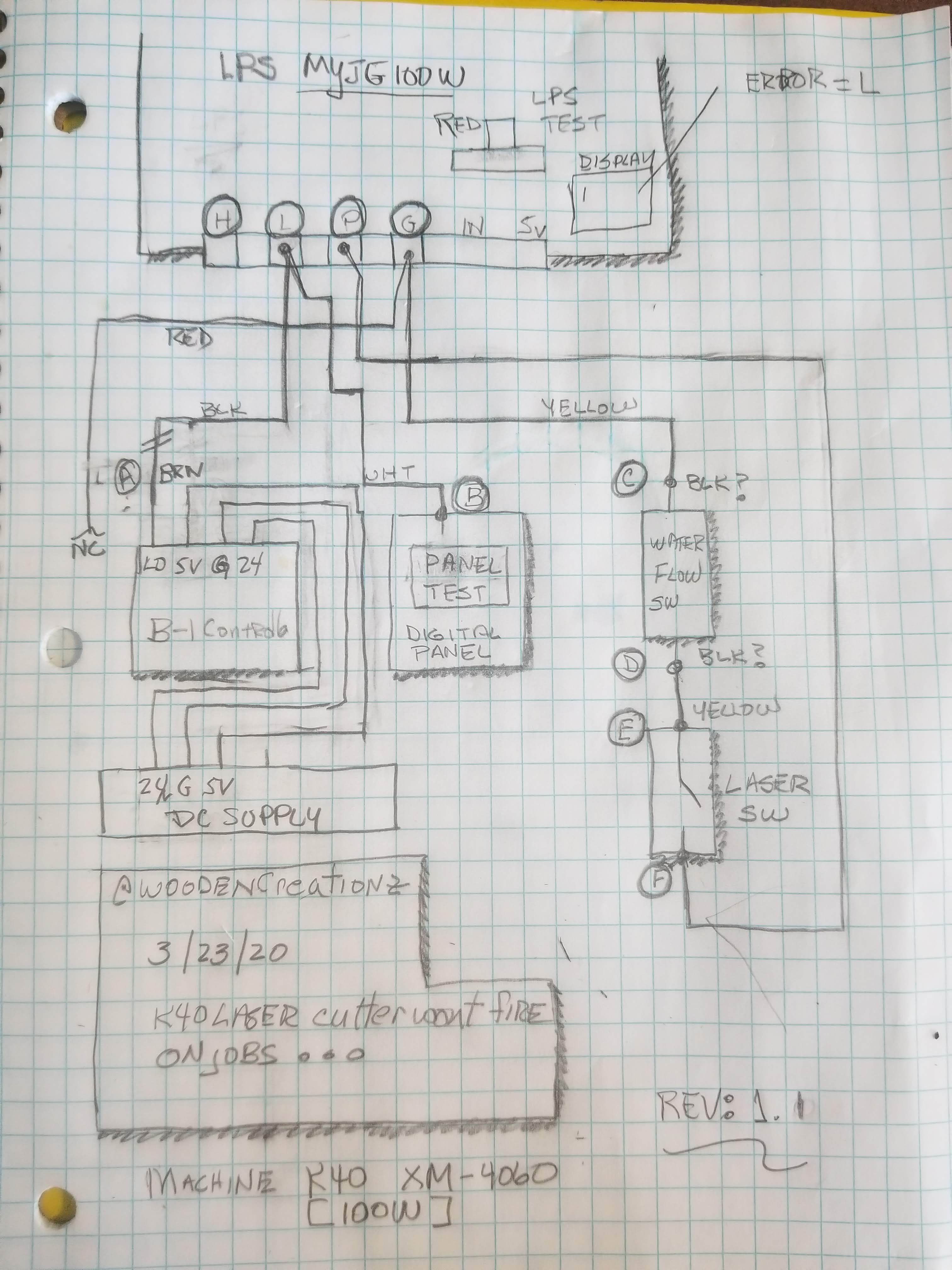
With the diagram below let me first summarize how I think this machine should work and then we can continue troubleshooting. This will help us troubleshoot in sync.
The drawing has circled letters that designate locations in the circuit.
How it works: L-A: this is the PWM signal coming from the controller. It is a low going signal that has the 1-0"s intelligence that control the laser on-off during cutting in a job. This should normally be high (5V) when nothing is happening or the Panel Test button is not pushed. L-A cannot turn on the laser if the P connection is not at ground.
L-BL: this is the panel test button by providing a ground it simulates the L-A function being ALWAYA ON when pushed. [it’s strange that pushing the panel test allows a job to run correctly it should just keep the laser on?]
P-G: this is the interlock circuit. When P is not at ground the laser will not fire. This means that the water flow switch and the Laser switch need to be shorted (0 ohms) for the laser to fire. When either the water flow switch or the laser switch is open P should be high (5v?).
G: is the ground reference for the LPS control circuitry.
IN: is the power level control and it should vary from 0-5 V as controlled from the digital panels power % functions.
5V: this is the supplies control voltage and should be a constant 5V when the machine’s power is on.
Anything sound or look wrong?
With this level set, in the next post I will continue the troubleshooting discussion.
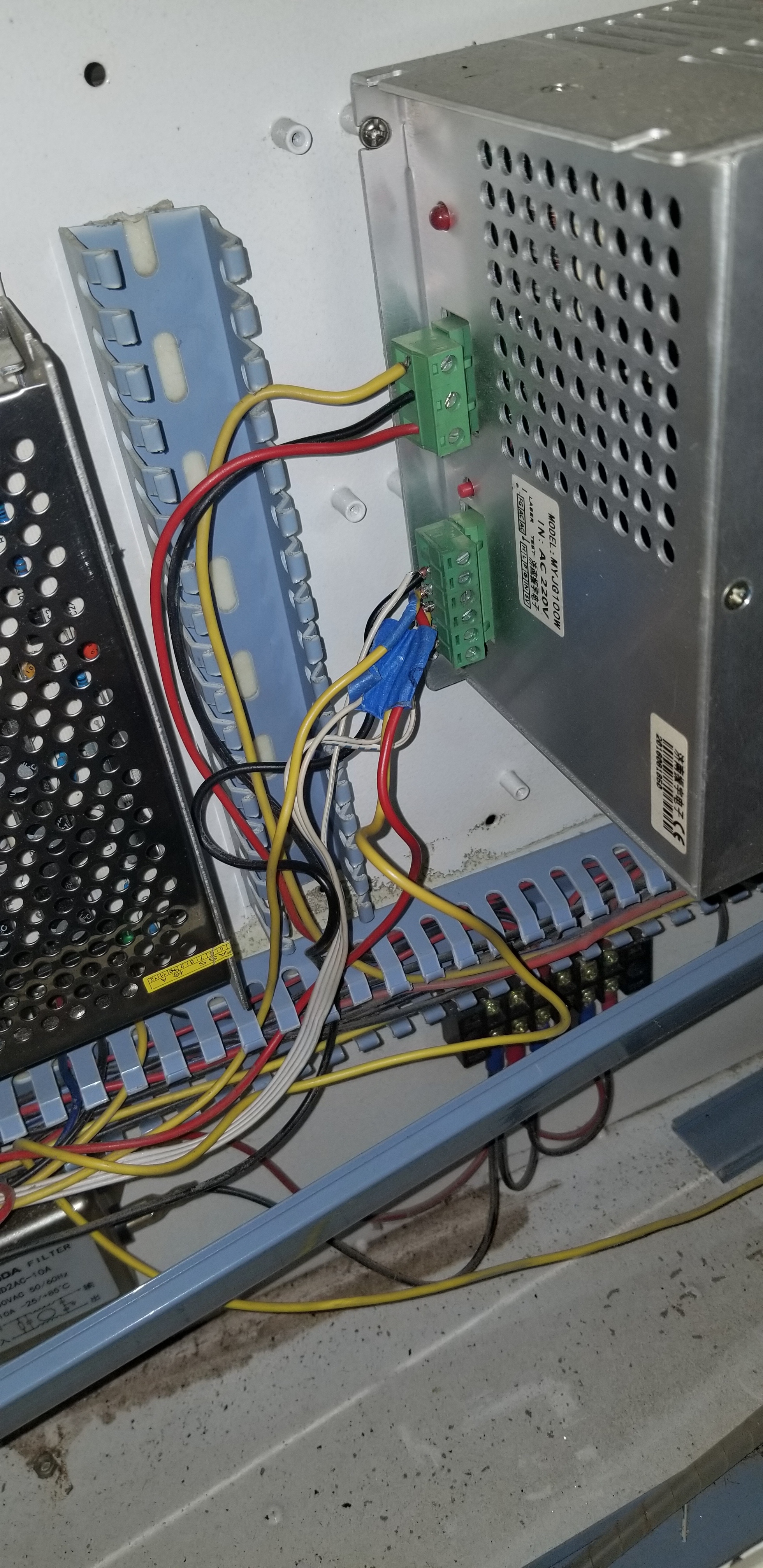
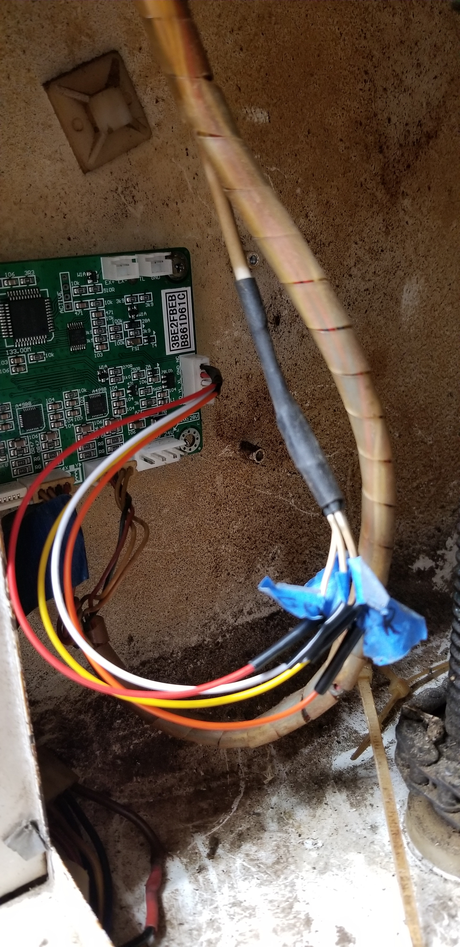
This diagram is exact to my system. Thank you for taking the time to make it so we all better understand. Give be a few minutes here and I will get you the results from testing the laser again correctly with the multimeter. I too questioned why the black cable goes to grnd on the controller board. I belive that to be a wrong statement as it is going to 5v. The wad of cables is in Cable wrap. And it’s that plug that the black cable is in. I have added the picture of its setup. Test coming very quickly of the water flow sensor.
Note: It may seem like some of my questions are redundant. They are no reflection on you or your answers. It usually means that there is something that is inconsistent between the question and the answer that needs further inquiry and investigation.
Below is an important assertion that I need to check in with you yet again to ensure that I am not taking us down a rabbit hole…
Configuration that works: When you run a job and push the “digital Panel Test button” the machine cuts properly.
If the above answer is “YES” then these assertions must be true.
Since we have a working case where the machine cuts properly then:
The L-A connection must be working and therefore the controller, LPS, water sensor and Laser Enable button must be working?
The interlock loop must be working as the machine operates normally when the Panel Test button is pushed while running a job?
The L-B connection is somehow enabling the LPS to operate whereas without the Panel Test button asserted the LPS does not see the controllers signal. [this makes no sense as both B and A are connected to the same point.] When the test button is asserted it must somehow allow the control signal to be seen even though they are connected to the same point??? I need to look at my schematic to see if I can logic this symptom. Note: there are some internal diodes in the LPS that can provide weird control symptoms.
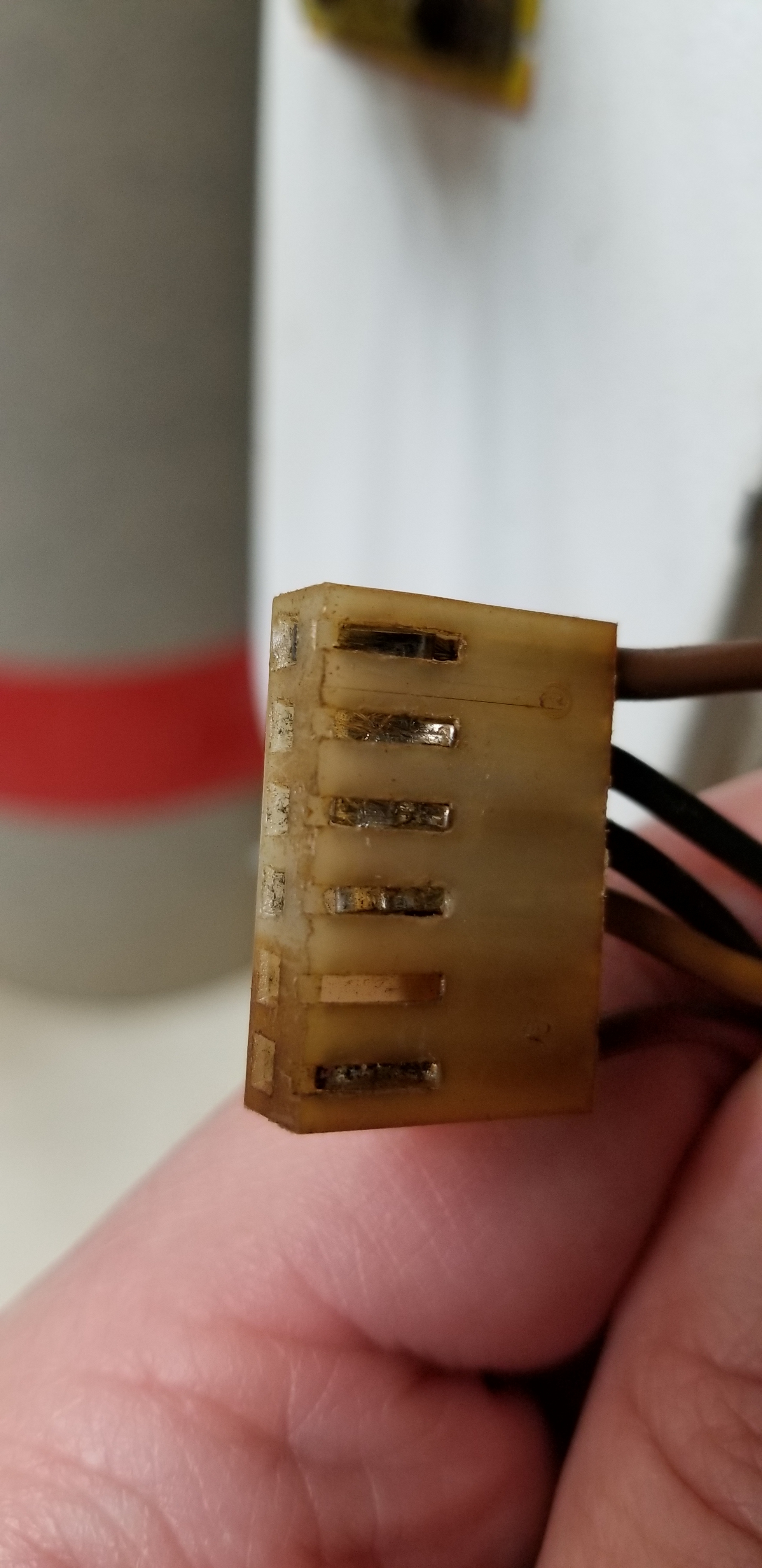
I have taken the wire wrap off the wires going to the Controller board and have and pinpointed each individual cable and the location they go to. Please reference the picture provided to help with your determination. I have plugged and unplugged the cables mutliple times and the metal connectors inside the ends of the cables arent what they use to be. I have ordered new cable ends and will be replacing them very soon. (I dont think this is the cause of the “L” message… The cable ends just are that nice snug fit you get when its brand new. I have tried firing during a job many times and held the wires at the controller board to make sure I dont have a loose connection. Never has it acted to be a connection issue in the wires.) But they are getting loose and will be replaced. I fear though this is not the cause of the “L” as the laser stopped working when I was in the middle of a cut and it got weaker and weaker and then just stopped… And I never touched anything… just watched it occur.
Also I have tested the Water Flow meter by cutting both black cables and testing with the Multimeter. When water flows it does provide feed back in the multimeter (Numbers change)
Video proof of this. But now when I soldered the wires back on… the Chiller still reads LL. As if its not seeing it, because it was giving me a degrees of the water temp. I have reversed the cable ends and soldered them back opposite… Still shows LL on the chiller… It is pumping water, it is NOT setting off the alarm and the Normal light is lit up green. I have ordered a new water sensor and will be delivered Tuesday so I look forward to replacing it defective or not im ready to get past this “L” error
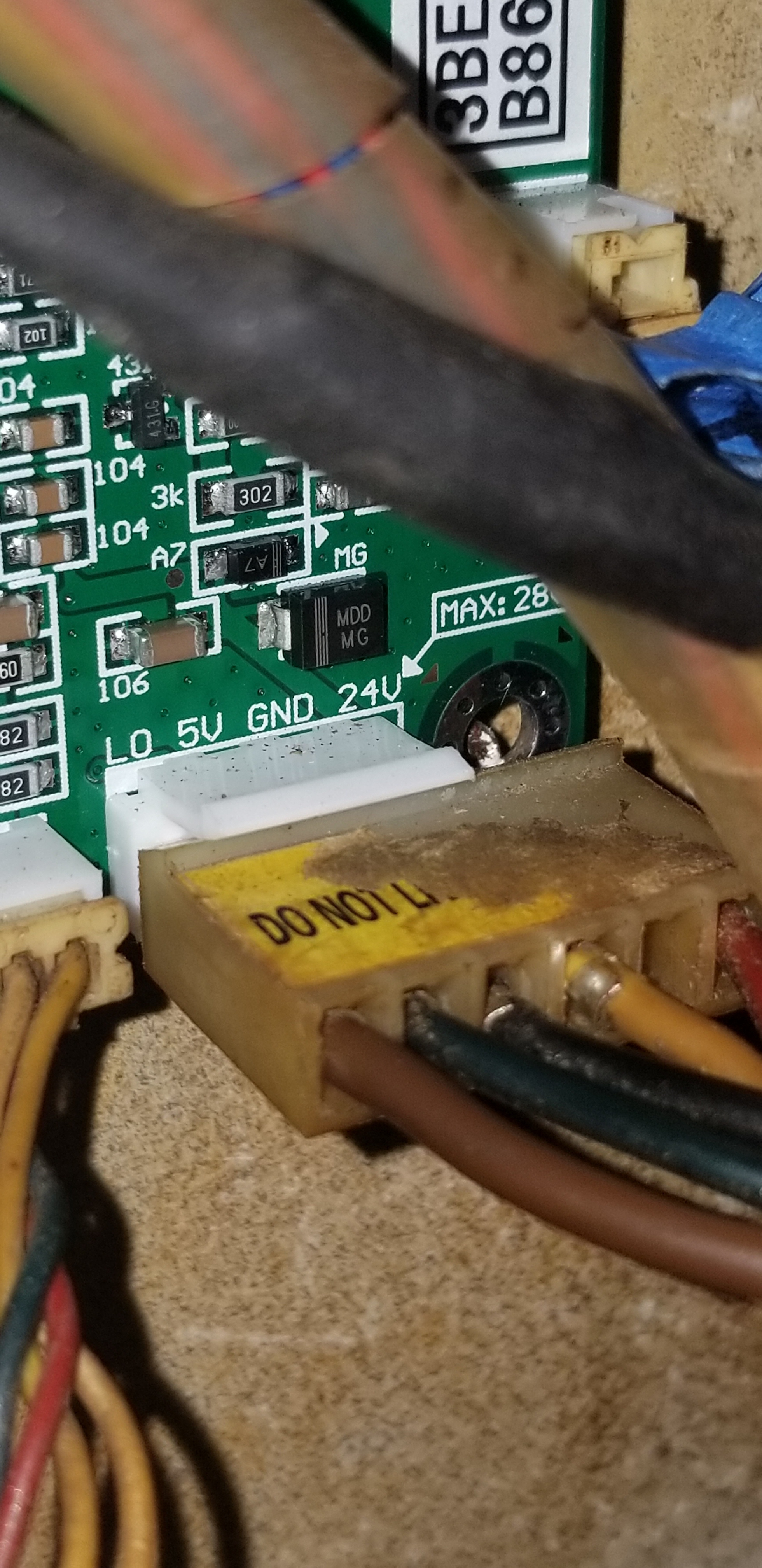
1. Previously we said that the L-A wire was black. The LO wire (which should be A) on that controller picture is Brown??? Please refer to the picture. I have all the cables labled from the controller to the LSU to the metal box. Again all cables were unwrapped and followed one by one to be sure.
2. That connector looks strange in that it has more pins than the controller. There appears to be a red wire not connected to anything. What is it? No clue why they connector is longer than the pins given. Thinking a larger board must have been on it at an earlier time. The RED cable goes to G (Ground) on the LSU. Again its been like that for 2 years no issues.
3. Where is the 24 v coming from as the LPS does not have 24V? Please refer to the picture. The 24v cable goes to a metal box in my laser cutter along with the Blue and Black cable. You would likely know more about this box than I would. And could this possibly be the part that bad? I have not seen any numbers on it so I can research it more.
4. What is the history of the machine has it been modified from stock? Like I mentioned before. I have purchased this from a CNC company that used it to get started. I have used it for 2 years non stop for production for my business and with it down, im presently out of business until I can get it going again.
Hopefully I have provided enough info to help determine a suggestion for by passing the waterflow to see if it will cut again, or replacing the LSU or weird metal box i am not sure the name of. Again I have a new Water flow sensor on the way. Unsure why the Chiller wont read it any more… But that should be resolved quickly with the new one. And again I am replacing plastic cable ends to give me a much snugger connection that plug into the controller board
This notion just dawned on me while I was looking at the LPS input circuits:
Up until now, you have reported that the machine will CUT with the panels’ TEST button pushed.
We learned from the wiring diagram that the TEST buttons function connects to the L of the LPS as does the job signal from the controller.
If the TEST button is held asserted that holds the L pin low (on). Would the machine cut correctly since the laser is on and the carriage is moving??? Cutting might work but every other type of job would not?
We can test this by running a non-cutting job and see if it works correctly with the test button pushed.
1. Try doing an engraving while holding the TEST button-down.
I have held the test button down and I can cut out jobs. I have cut out circles and it has no problem in 1/4 plywood. Problem is its constant so when it moves off the line I’m still cutting as it’s a continuous fire…
Let’s do this Don… I have a new water flow sensor on the way. I have ordered new cable connectors for multiple wires that go to the controller. They are getting loose/ internally bent as I plug and unplug them. I don’t think this is the cause of the L message as it occurred when I was in the middle of a cut just watching the laser. But I have worked the wires loose changing and testing them over and over… And I need to fix this before we continue.
I plan on getting a new power supply as well just to see if can get past this. This will take sometime to get and may not be the issue but it won’t hurt to have a spare and help figure this out. Delivery April 2nd.
All other parts come in Monday, Tuesday, and Thursday.
I will update you once I have these things in place and I have solid connections before we proceed further… I will update you of what I find and appreciate all the work you have done with me so far… Fingers crossed one of these parts fixes the L message.
Like I mentioned the wire connections are a little loose now so I need to wait and get those replaced so I’m not chasing my tail. But test button on the panel and psu both just fire the laser at the power I set it to. It does move the head on engrave. So techically I could have it follow a blue line and turn the power down and and hold test down. But thats not really truly running the job… Thats me just holding the button down as the head moves… It doesn’t shutoff when it moves to an new section… Holding a test button is constant light being fired… And it ignores the job… I will test each thing I replace until I get a result. Will let you know more next week. Brian
The controller is moving the mechanics properly controlling the motors from the move commands in the job.
When you push the Test Button during this job that holds the laser on. However, the control of the laser, in that case, is not coming from the controller. You are simply holding the laser on while the carriage moves as directed by the job.
If this hypothesis is correct it means that the controller is not controlling the laser only the mechanics.
Proving this to be true is important because that would mean there is something wrong with the L signal coming from the control board [A-L signal] while everything else is working.
**We can test and prove this to be true or not by printing a job with an IMAGE IN IT and NO CUTTING **
I understand that you want to make improvements in the wiring that is a good idea. I also recognize that you have ordered replacement parts, those may all be good things to do anyway and I am not necessarily discouraging trying them.
I want to get your business up and running as soon as possible but I fear these actions are not going to solve the problem. That said I have been fooled by this machine many times before.
My worry is that your symptoms and our tests do not point to bad connections and LPS. In fact, we have not really narrowed in on what is causing this behavior.
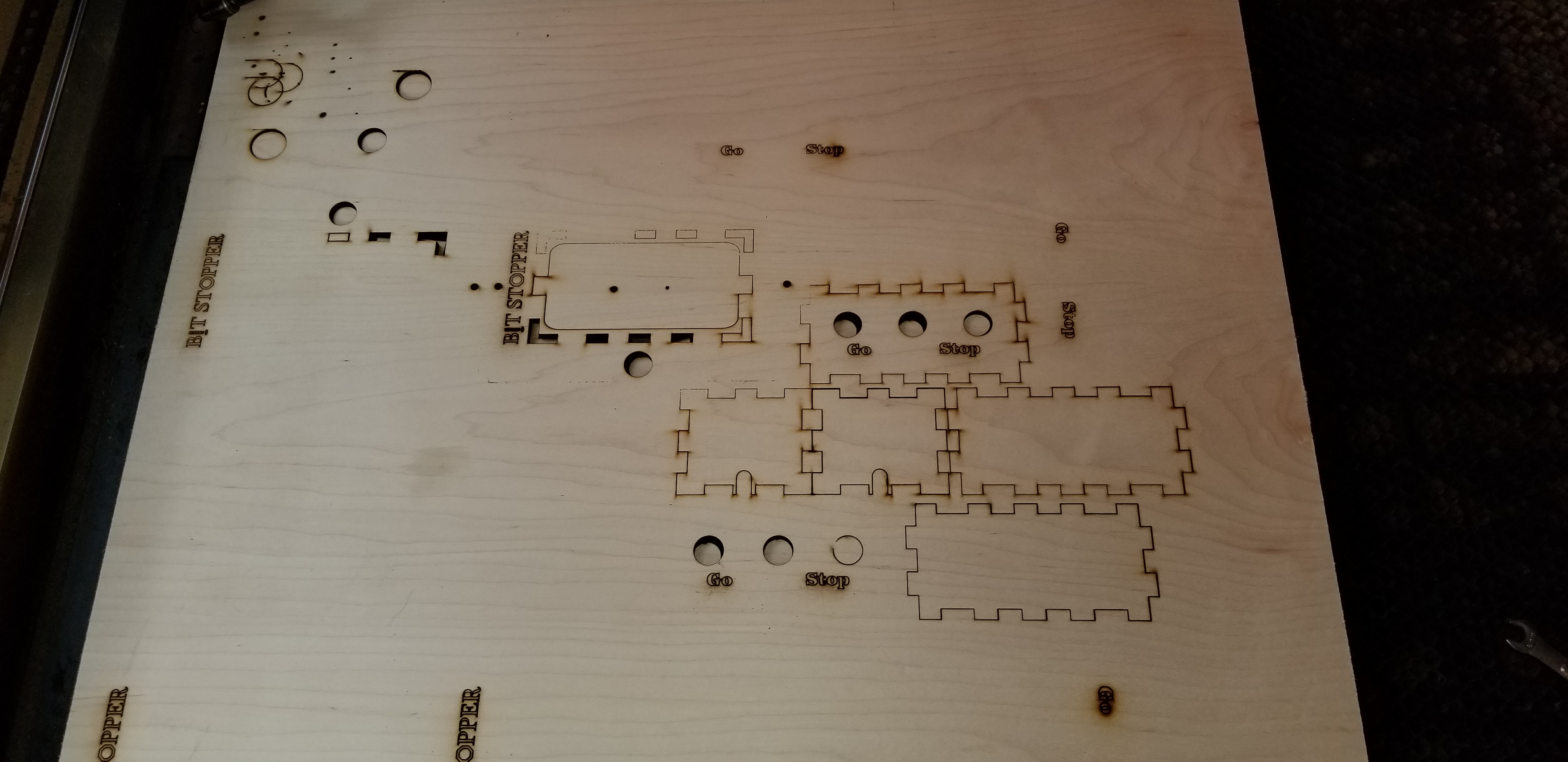
It’s, for this reason, I am again suggesting that while you wait for parts try and burn an image in the same way you are doing the cutting and post a picture of the results.
Also, post a picture of the job you have been trying to run when this failure started.
I have received and replaced the Waterflow Sensor. Its been rewired and the chiller now sees a temp again. Next, I received and rewired a strand of wires that go to the controller board that control X and Y… Every wire literally fell out of the cable connection from all the testing… Thursday I have a new cable end coming to rewire the L signal wire. The female “L” signal wire is worn out and wants to pull out of the cable end and the other wires in this cable end are bent from all the testing… I am totally with you on getting this dude up and running… Give me a few more days to have a this connection fixed and see if the new cable or the new water flow sensor has resolved anything. I have a new power supply on order from aliexpress. I requested 5 day shipping but its looking delayed and I cant get one here any faster. Again the power supply may not be the issue. But give me a couple days here to give you accurate results with new cabling and a new water flow sensor.
I have added the last thing I was able to laser as it slowly died (Before I reached out to you). Ignore the top left corner. I was test firing (As test firing still works on test panel and LSU test button)… But you will notice the laser lost more and more power until it stopped cutting all together.
Again, adding some picture of the cable ends that are falling apart. New wiring is the new connection replaced, chiller now reads temps again after waterflow sensor, new waterflow sensor installed, and pic of last thing I was cutting when it died.
Talk to you Thursday night once the new “L” cable is installed and I can fully test again.