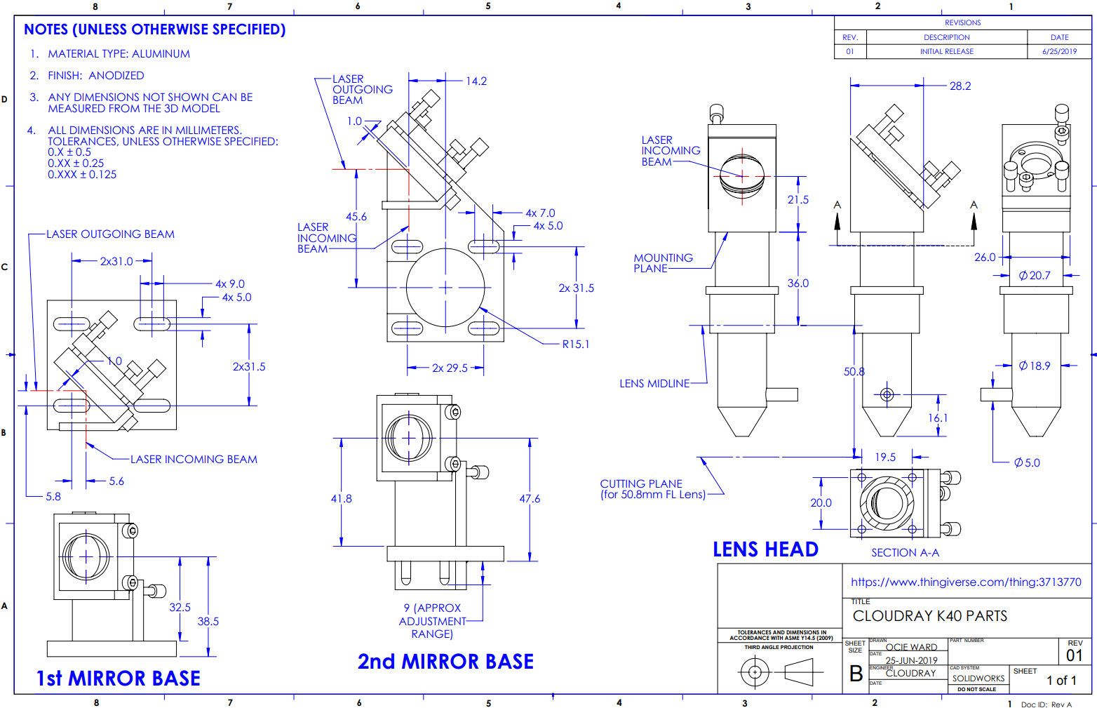
Someone did a cad model of these mounts and put it up on thingiverse. The cad files, stls and technical drawing are available in the link below for anyone interested. The technical drawing will save me from having to do the measurements I will need for my installation.
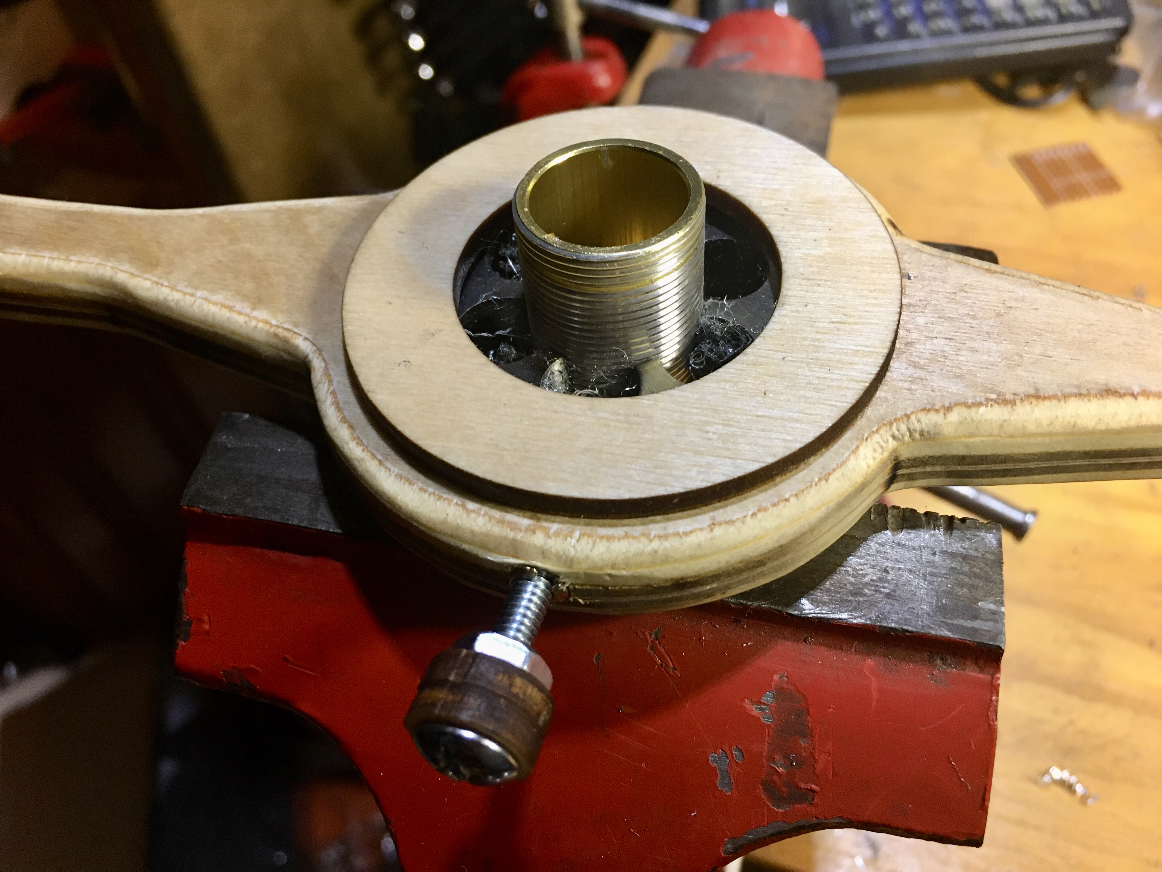
Decided cut down the top part of the down tube to reduce loss of available z-height. The top of the tube has a M20x1 mm thread. I didn’t have a metric die that big so I had to order one. The cheapest one I could find was this one from Amazon.
The outside dia. of the die is 45mm so my current die wrench wasn’t big enough. Rather then spending the money for bigger die wrench I decide to make one from laser cut plywood.
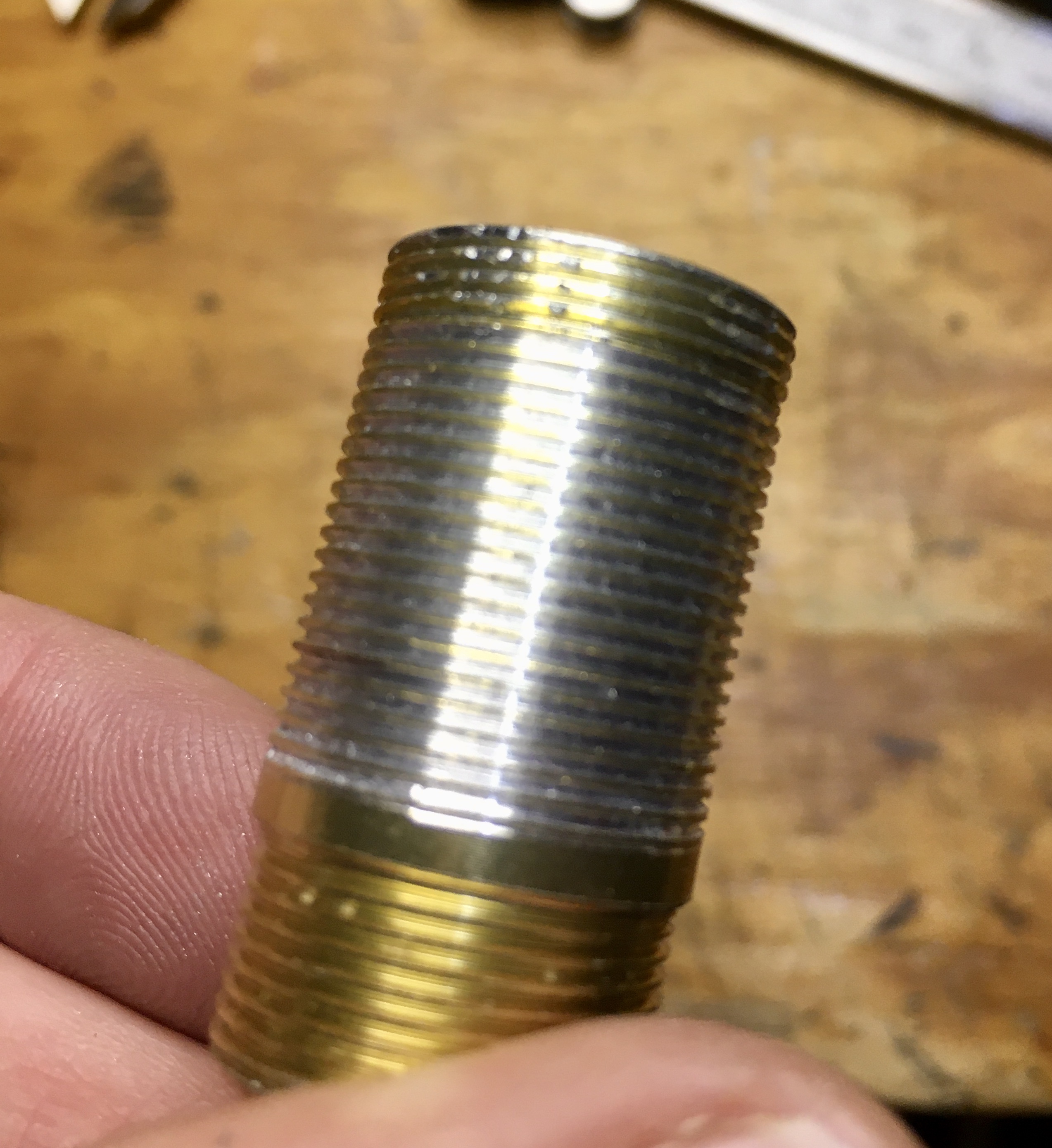
Rather than cutting the tube and then cutting threads I decided the easiest thing would be just to cut thread down the whole tube and then cut it to length. To hold the tube while cutting the threads I installed the adjustment ring on the bottom threads, which are different, tight as far as it would thread. Clamped the ring in my vise and cut threads until about 3mm from the start of the bottom threads.
The ring was jammed tight after cutting the threads and to loosen it up I grabbed the top of the threads, I just cut, with some plies, since I don’t care about the top, and the ring with some other pliers.
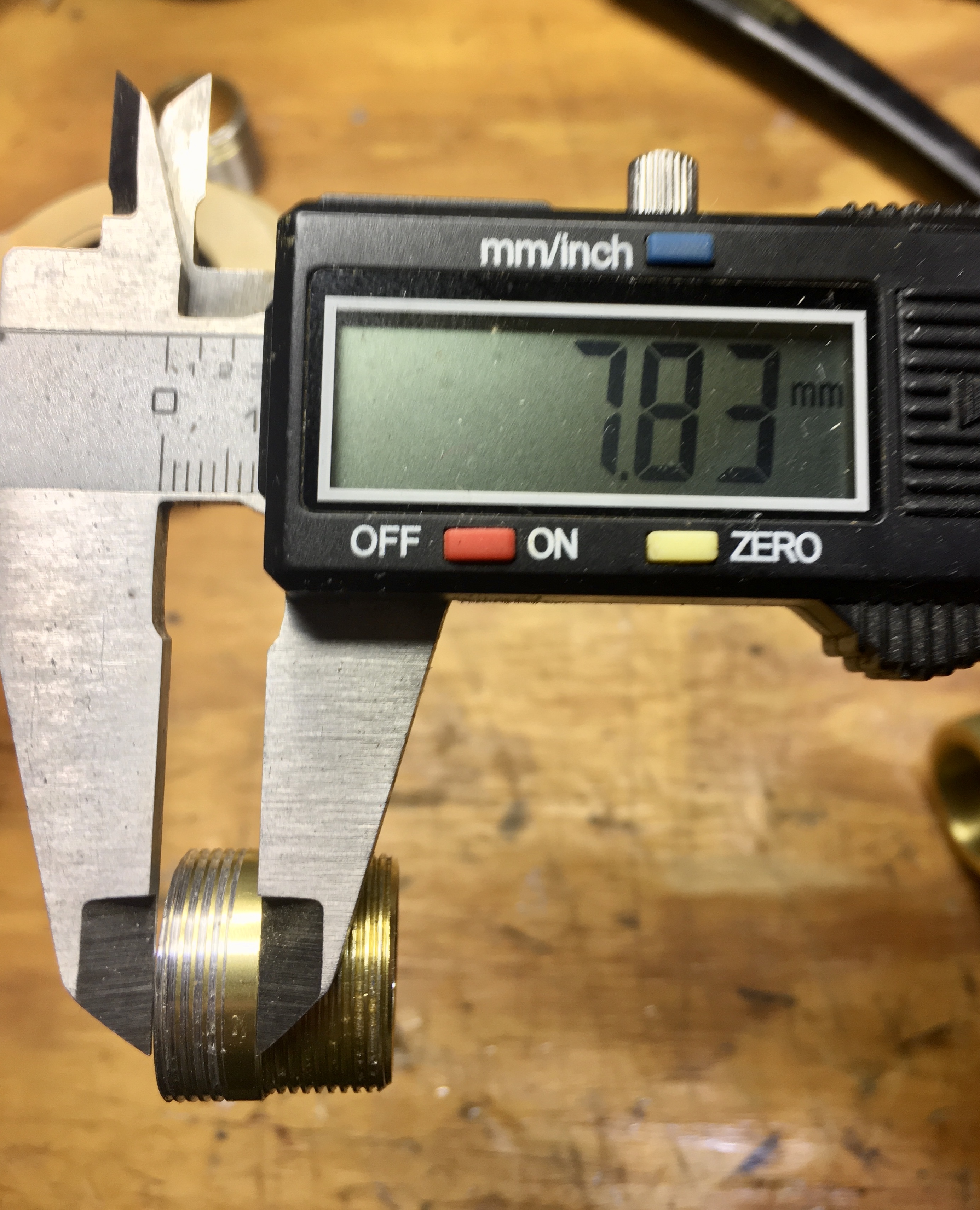
Marked a line at about 5mm of thread from the bottom. Inserted a 0.5" dia. wood dowel, to hold and steer, and carefully cut the tube on the bandsaw. Left with about 8mm to the start of the bottom threads.
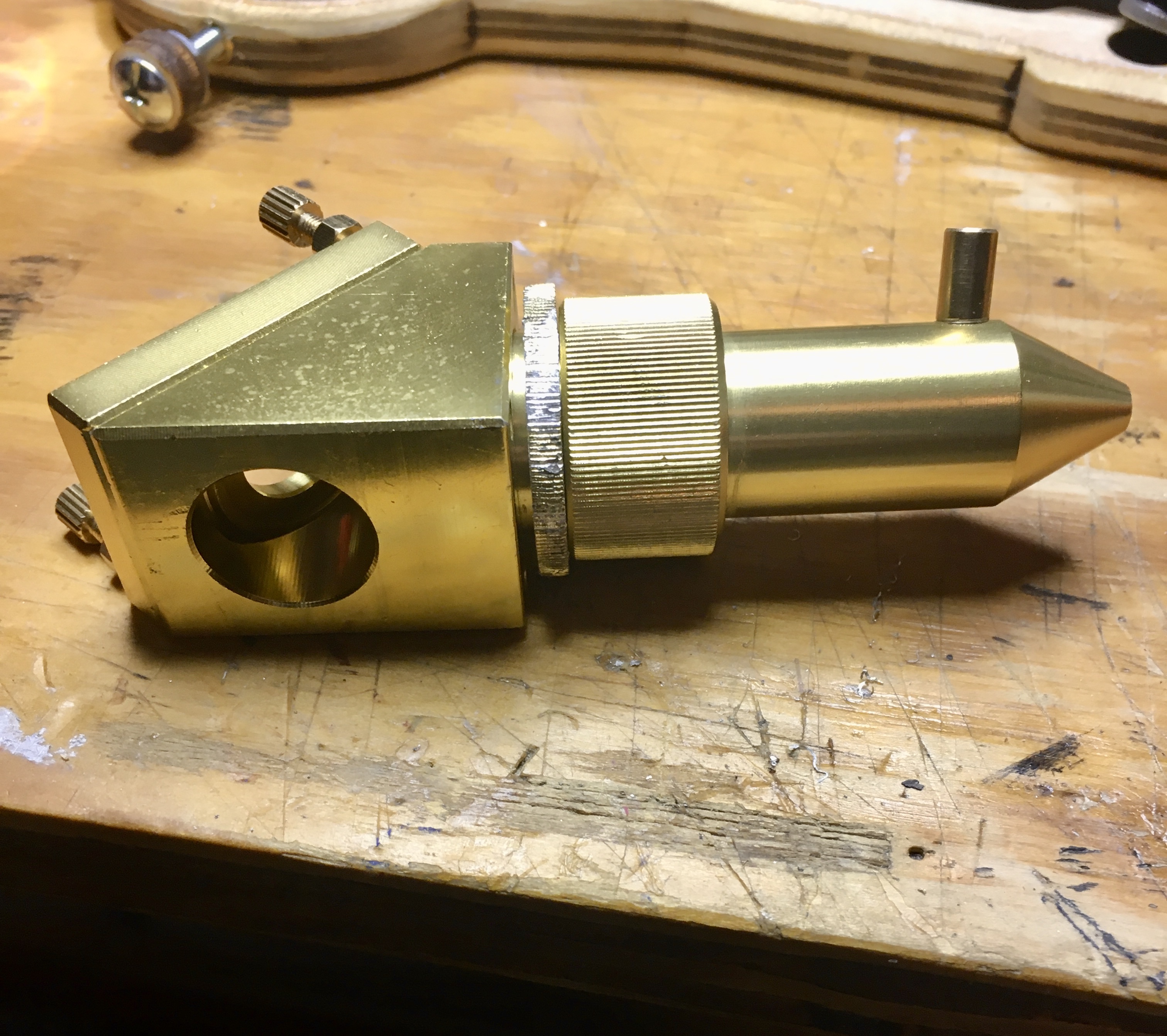
The bottom tube and coupler are one solid piece as the lens sits at the bottom of that coupler section. So you would be looking at cutting a section out of tube and then somehow rejoining the sections.
Installed the second mirror mount to get this started because it appeared to be a direct drop in replacement.
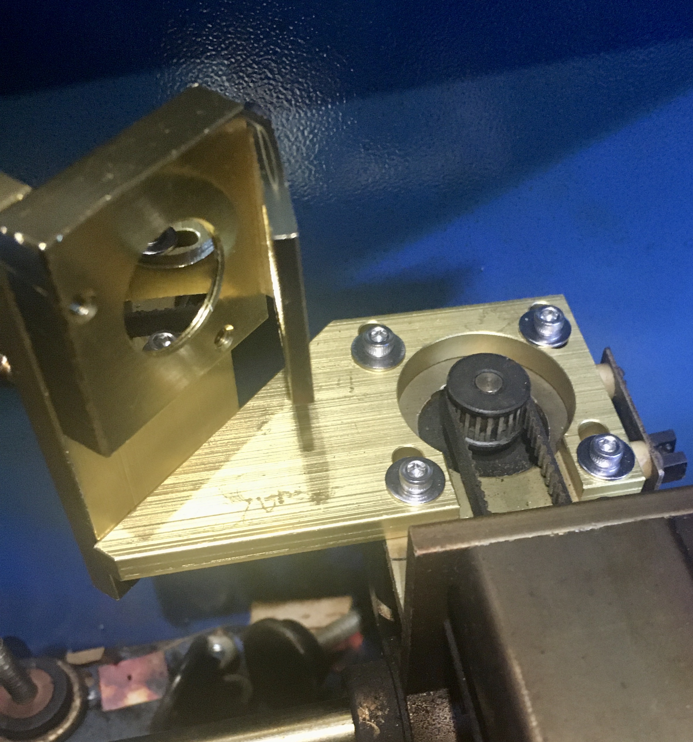
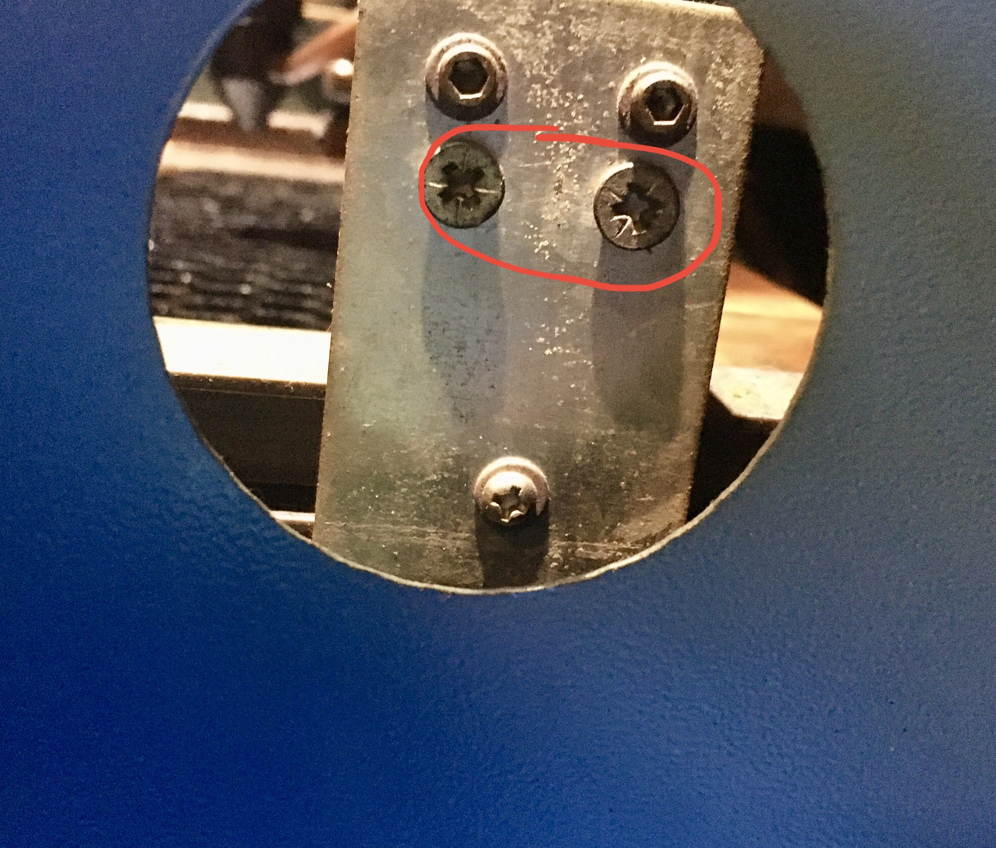
The mounting plate goes over the motor, around the pulley, with a section milled out for the belt to pass over. This means you have to loosen the x-belt and remove it from the motor pulley. If you haven’t worked with the x-belt, the belt tensioning screws are on the right side. You access the screws from a hole in the wall between the laser compartment and the LPS compartment. Loosen both screws, shown circled, about the same amount until you can remove the belt from the motor pulley.
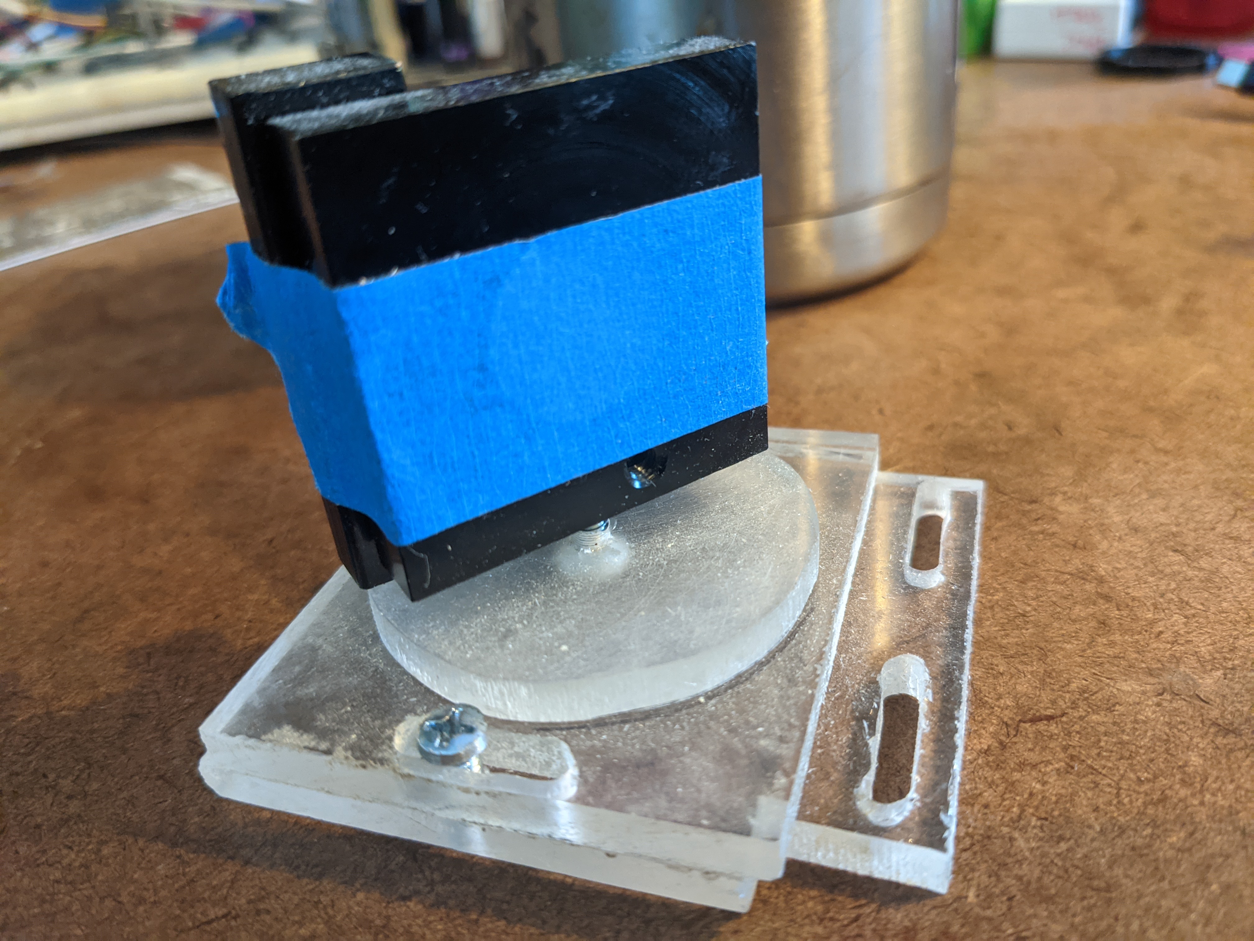
Mounted the new mirror mount using 4 M3 x 15mm stainless steel hex cap screws with washers and reinstalled the belt. Be sure not to over tighten the belt which can cause binding.
Lightly tightened the new mounting screws just enough so I could still move the mount side to side. Placed a piece of tape over the alignment wing and moved the mount back and forth, with test fires, until I got it centered on the beam. Tried to keep the back edge of the mounting plate parallel to the edge of the motor. Tightened all screws.
Aligning the mirror to the laser head actually went fairly quickly. Looks so purty
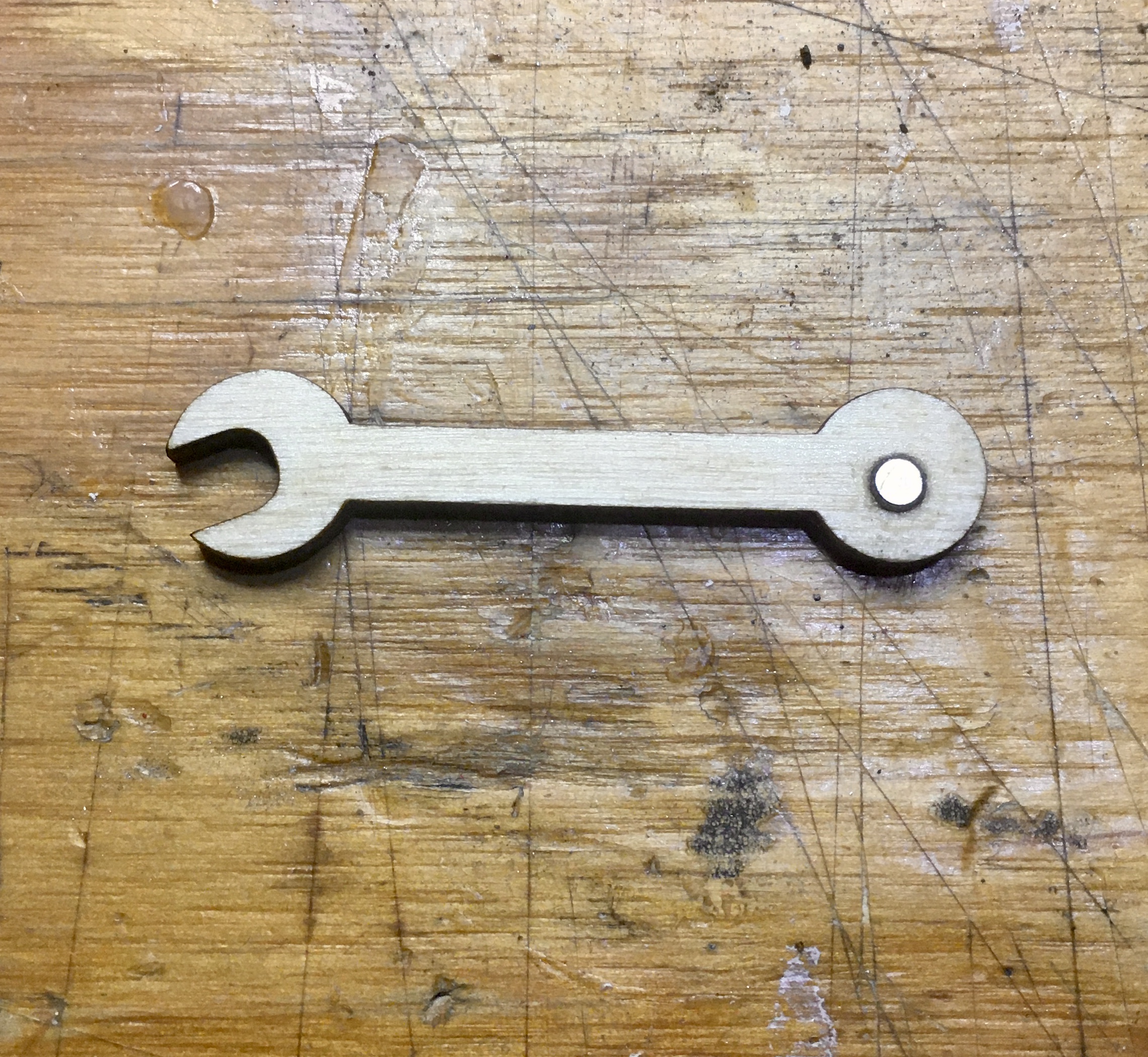
The locking nuts on mirror adjustment screws are 5mm. I don’t have a 5mm open end wrench, so I laser cut one from 1/8" ply. Here is the SVG file if anyone needs it.
I embedded a small 3mm magnet into the end of mine so I could stick it to the inside of the compartment to keep track of it.
Yeah, the basic set of metric wrenches I have from harbor freight only goes down to 7mm. But fortunately I don’t need super amounts of torque and I’ve been finding laser cutting my own wrenches super handy.
It is almost a catch-22, you cannot adjust the mirrors unless you have the proper tools but you could cut your own tools if your laser mirrors are properly adjusted.
Tool making is a big part of the 3d printer groups. The first thing I printed was vernier caliper. I’ve also printed a couple of wrenches. Once you get hooked on these toys, your imagination goes wild…
I just looked at this photo again.
If you cut out the area of the bracket below the belt could you put this bracket on without removing the belt??
I dont think with 4 mounting screws this would weaken the mounting of the mirror???
Since the #2 bracket forms a C around the motor why does the belt need to be removed at all? The motor comes up from the bottom of the Y carriage. The M3 bolts go thru the #2 bracket, the Y carriage and then into the motor frame.
WELL CRAP. Disregard my top post. I went back and looked at the big pic you posted of the part set and realized I missed the small tab between the legs of the #2 bracket. I agree that you should be able to remove this tab as the original #2 is not near as row bust.


 Looks so purty