I need help
I use Laserweb4 and arduino uno with GRBL 1.1 for engraving.
Now I want to connect the co2 laser to the Arduino Uno.
Who can help?
If i connect according to this scheme, the laser will work correctly?

F
Following … Because im interested in this subject
Ok
I think the pin out for GRBL in Arduino has changed, research for that speacially for 1.1
Cannot search at the moment. But look for spindle connect on GRBL 1.1 arduino
Unfortunately I can not find. Searched the entire internet.
Be warned- the laser fires full power at 0 volts and grbl sends 5 volts for full power. You can configure the grbl software to flip the behavior but the laser will still fire for a split second while the arduino starts up. I added a simple transistor circuit (found through this group) to flip the voltage around. Im much happier with this from a safety point of view.
@Tom_Traband Thank you very much for writing. I want to protect myself too. Maybe you know where to find information to connect?
@Tom_Traband I found in your post where you talk about it. But I do not understand where you connect transistor
https://plus.google.com/118210723591645186622/posts/7ZPHFSKfV2o
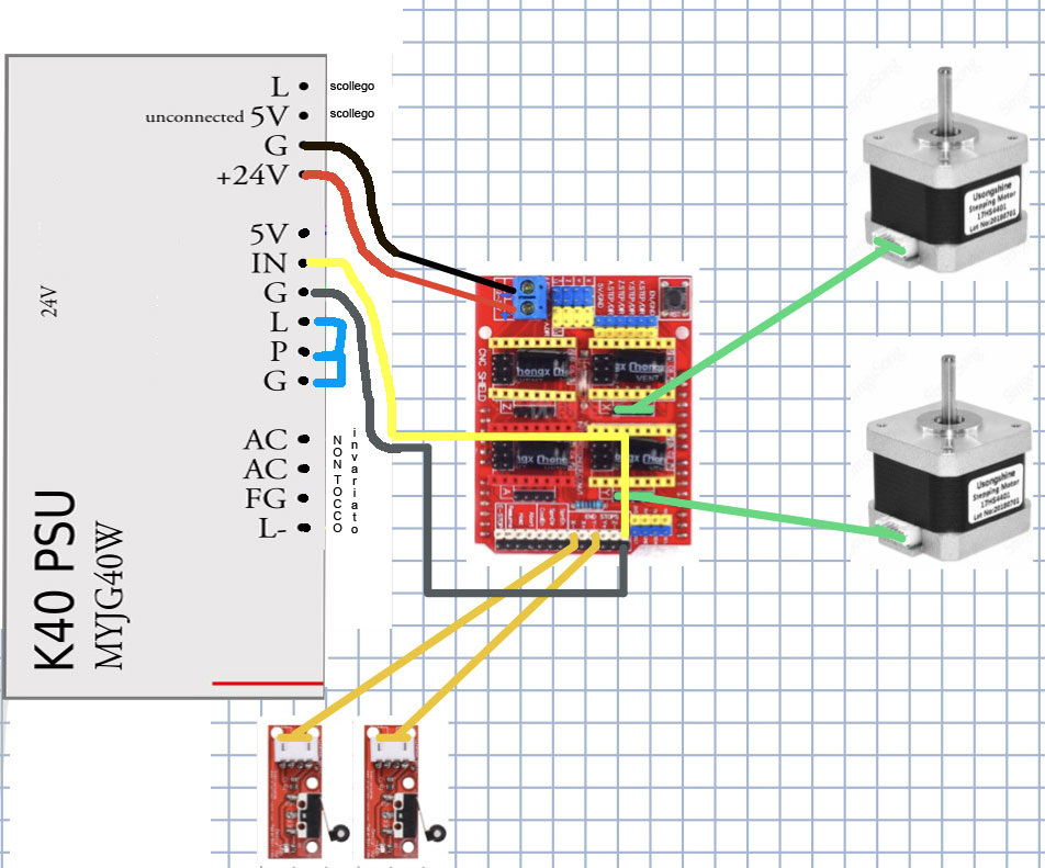
I use arduino uno and CNC SHIELD.
GRBL 1.1 and the program Laserweb4.
I’m trying to connect the power supply, but I can not.
Help solve this problem please
Found my own old post. On April 9th I linked back to this article
http://www.foxrobotics.com/2018/03/19/upgrading-a-k40-laser-cutter-part-1-control-board-upgrade/
Look for the section on the Laser Logic Board. This is working perfectly for me but I’m using Lightburn instead of Laserweb.
Now if i could find a way to clamp a dial indicator on the head so I could fine tune the 3d printed motorized z table…
It’s not needed to invert the pwm signal. Just use the TH input of the power supply instead of IN. TH is active high, L is active low.
More precise: TH and TL are activating the tube (digital) and IN is defining the power (0-5V).
You also need to connect the Ground of LPS and Arduino.
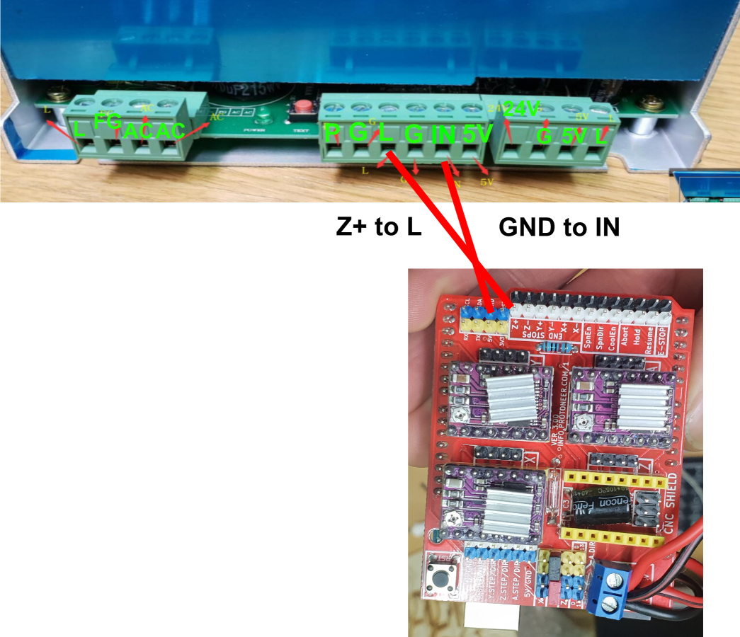
Ciao Claudio.
Riesci a fornimi lo schema di collegamento tra la CncShield e LPS?
Te ne sarei molto grato.
Hello Claudio.
Can you give me the connection diagram between the CncShield and LPS?
I would be very grateful to you.
@Danilo Please write in English on this forum. Using machine translation (like google translate) is OK. We know English isn’t everyone’s first language. However, we don’t have an automated translation service available here, so English is the common language here.
1 Like
@Danilo Please post a picture of your LPS (with cabeling) and the CNC shield, so I cann tell you how to connect. There are two versions of the CNC shield. The old one was made for Grbl 0.9, the new one is made for Grbl 1.1 and don’t need to swap the Spindle/Z+ pins.
Also read:
1 Like