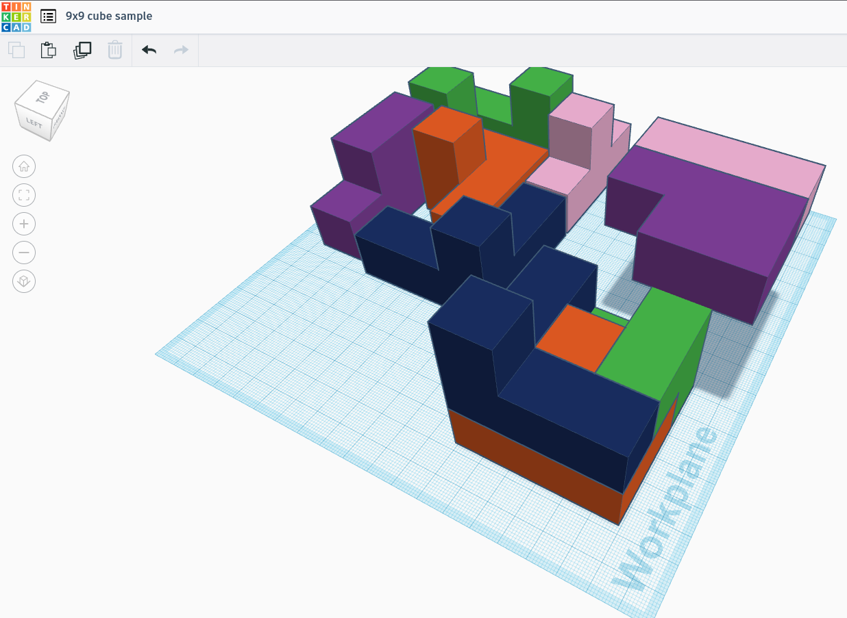
My daughter is learning perspective views in a class at school and to do this she made a 9x9 5 piece puzzle from 20mm cubes gluing them together. I thought I’d get her into CAD by showing her how easy it was to make her 5 puzzle pieces in TinkerCAD and then 3D print them.
The TinkerCAD part went really well and she picked it up quickly. The problem comes with 3D printing because the inside and outside corners don’t fit perfectly well. So I thought the easiest solution was to bevel the outside corners which interfaced with inside corners of the other parts.
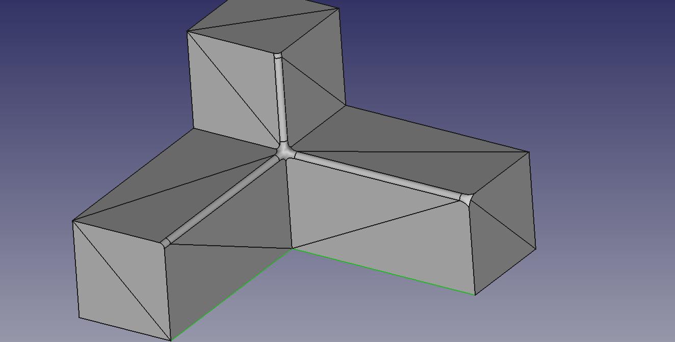
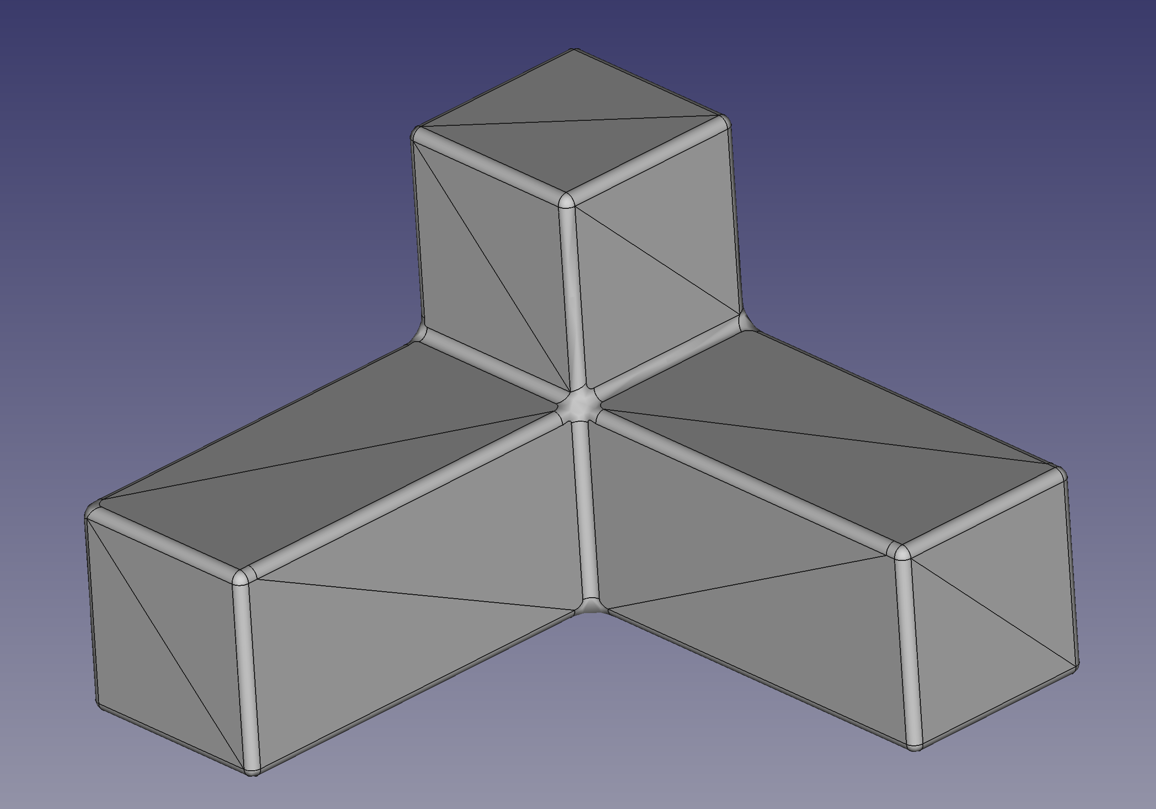
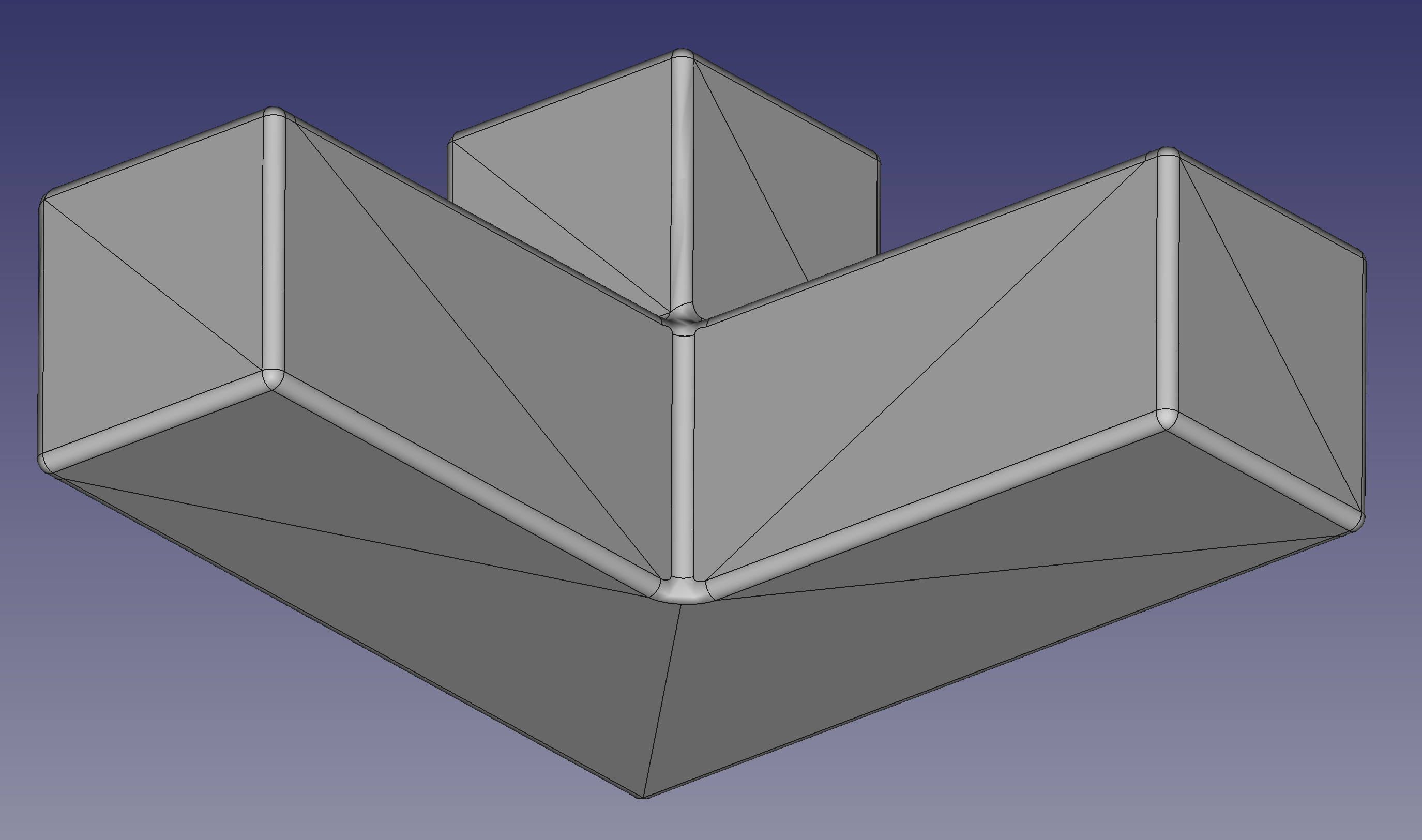
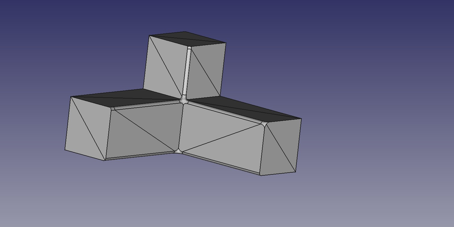
TinkerCAD does not do bevels and they have to be made with boolean operations of custom parts. So I thought FreeCAD might be introduced because I can import the STL, Create Shape from Mesh, and then apply the bevels. But not all edges can be bevelled( see pic below of what I could bevel and then the 2 edges I can’t bevel(highlighted)).
I’ve included the TinkerCAD parts and cube with the top layer shifted showing the Blue colored part I’m working on.
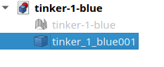
[tinker-1-blue.FCStd|attachment]
I will try creating the part from extruding a sketch in FreeCAD(bottom corner part), filleting it and then boolean-union a 20mm cube with the one fillet.
But that’d be a lot to ask a 13 year old where as importing the STL, converting to a shape then selecting edges and the fillet operation seemed more probable since conceptually it’s 4 ops; import, convert, modify, export.
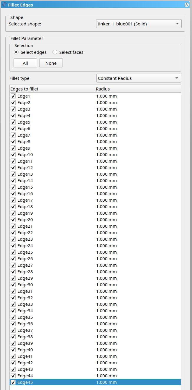
UPDATE: I created the part from 6 20mm cubes(much like she did with physical wooden cubes), then boolean-union all of them and then selected the edges to fillet and it worked. I will have to see if she gets it.
Too bad TinkerCAD can’t do fillets of edges. Onshape can but I found it less easy to use than FreeCAD. The class only has Chromebooks so FreeCAD is a tough sell to the teacher even if they had one or two computers which ran it.
First: Yes, there are more steps than I like when I’m trying to modify an STL in FreeCAD. I wish it were more intuitive, and the whole “run it on a Chromebook without rooting it and running a Linux container” makes this a stretch…
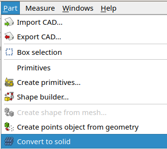
You were almost there! One more step needed for general work with the Part or Part Design workbenches, which is to convert the shape to a solid.
Just so anyone else who runs into this can easily follow, here’s the step-by-step from your FCStd file:
Delete the fillet:
Convert the shape to a solid:
Hide the shape, showing only the solid, and select the solid:
I still could not add just those 2 lower edges even if I created the solid. Leaving those ‘inside’ edges square would keep plastic away from the mating part and with the mating parts having a fillet the parts would fit together well. On the Makerbot the parts did not fit together well at those tight inside corners.
And thanks for reminding me that I still had a hollow object. I forgot about that detail of creating Shape from Mesh.
I was running 0.21 but from 22.10 and it would not let me add those 2 lower edges but I tried 0.21.0 from 23.06 and Voila! I took a non-solid one and tried the later version of FreeCAD with the edges it had failed on previously and it rendered the fillets. For 3D printing I need it solid but I think the solution was checking not only the version number but the release date.
I was also being particular about ONLY filleting the edges I needed since in some tests I was able to get the fillet subsystem to not fail on an edge if I also filleted some other connected edges.
That and the 9x9 cube parts would have some edges filleted and other not. But if it was something special, I would probably fillet the inside corners with 0.5mm radius and then the mating outside corner with a 1.0mm radius so that all edges were filleted but the tight ones were filleted for more clearance.