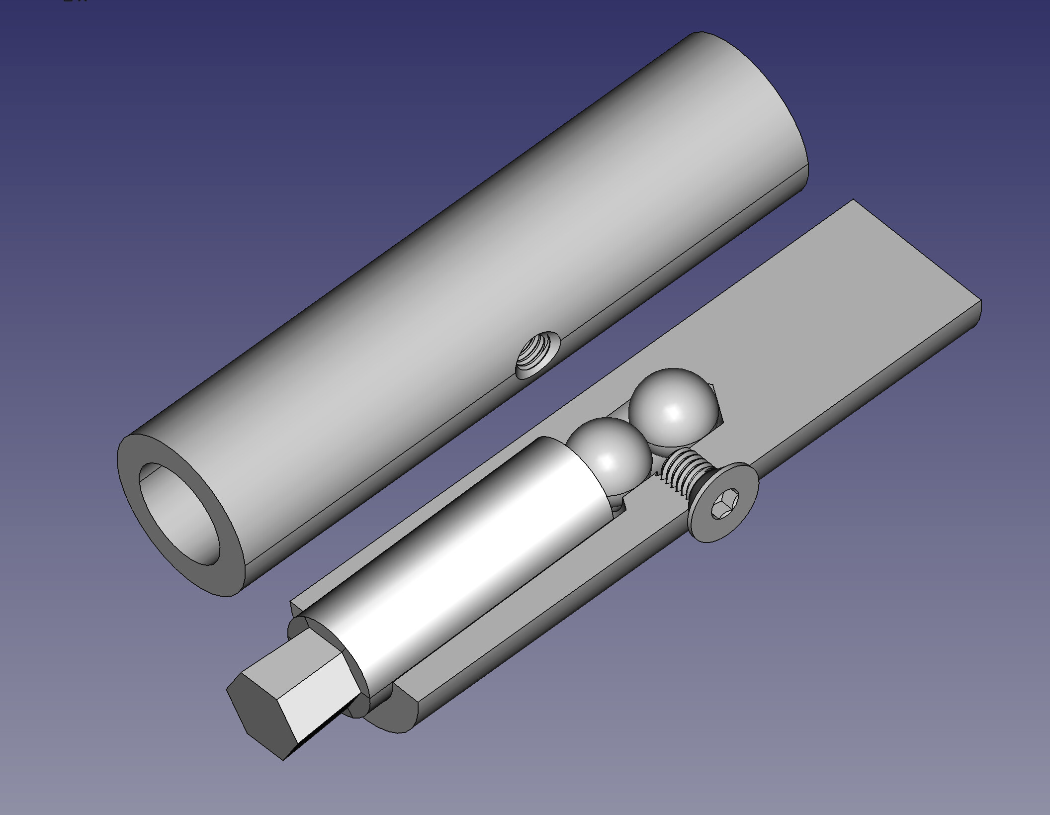
I can’t seem to stop experimenting with rotary broaches. But this one just looks like a round shaft with a slightly off-center hole in the end, so a cutaway view in FreeCAD probably shows the design better.
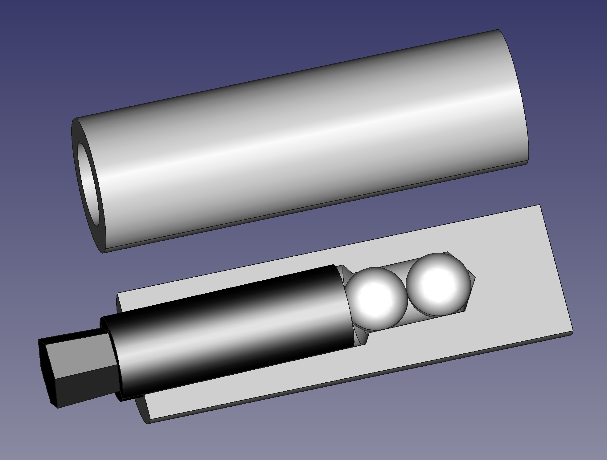
I had the idea that you only really need a ball or two and no other bearings, just a bushing. And I hoped that with a countersink screw as an air valve, this could be set up to extract the broach from the work pneumatically, with suction.
After two weeks of thinking through iterations on this, I finally made the experiment.
Didn’t take long, and I learned two things.
- My idea that this could be made with only a drill press appears bunk
- The pneumatic tool extraction doesn’t work
However, I can therefore make the design even simpler, leaving out the useless air valve screw. And as long as you don’t mind removing the broach from the work after cutting by hand (probably not a big deal for a few cuts anyway), it works really well.
What I learned
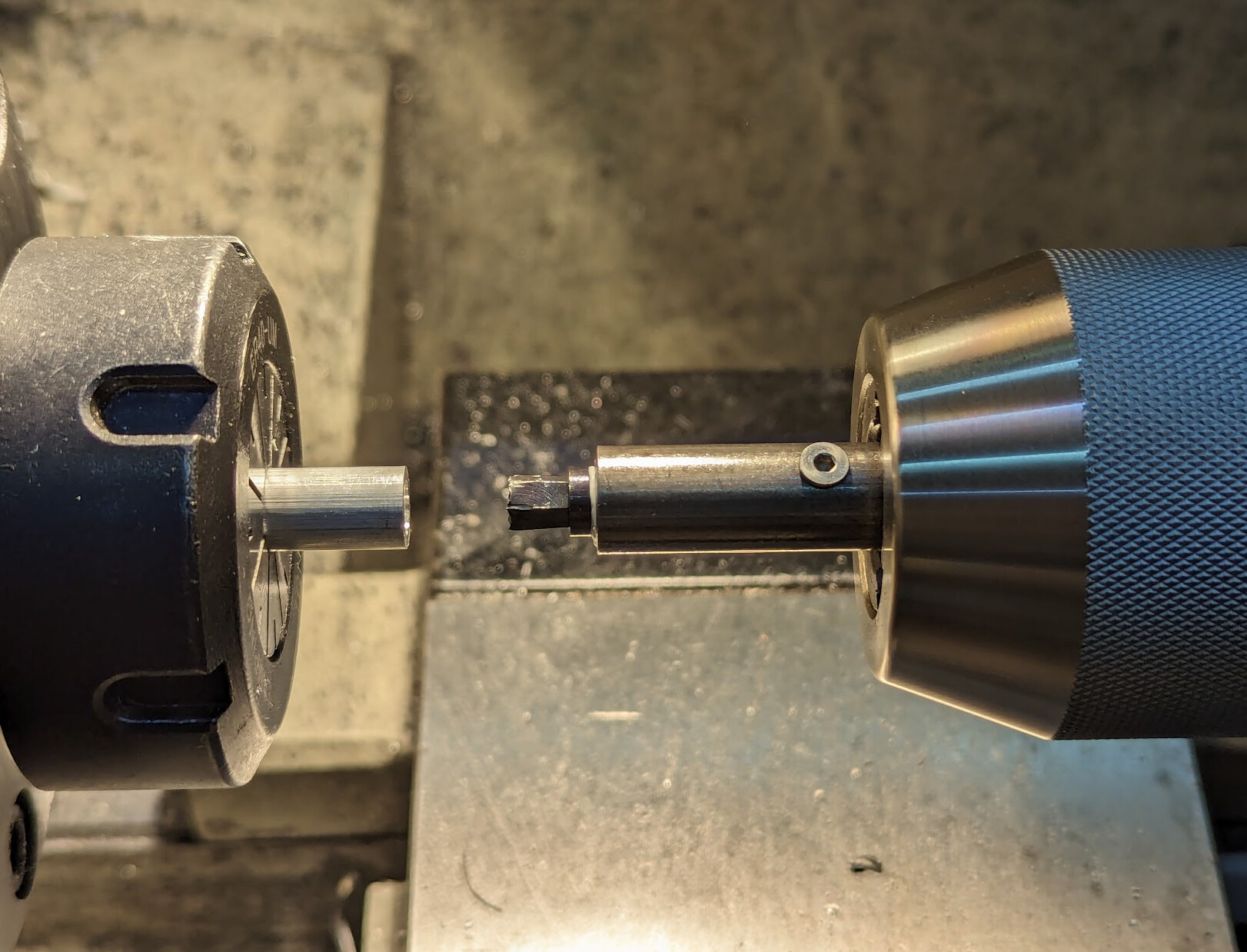
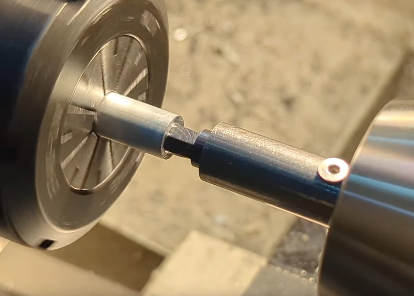
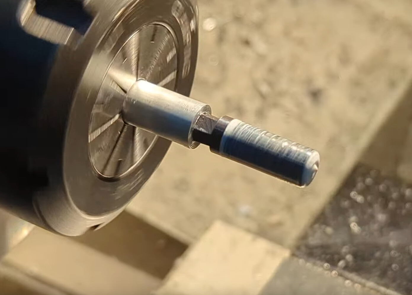
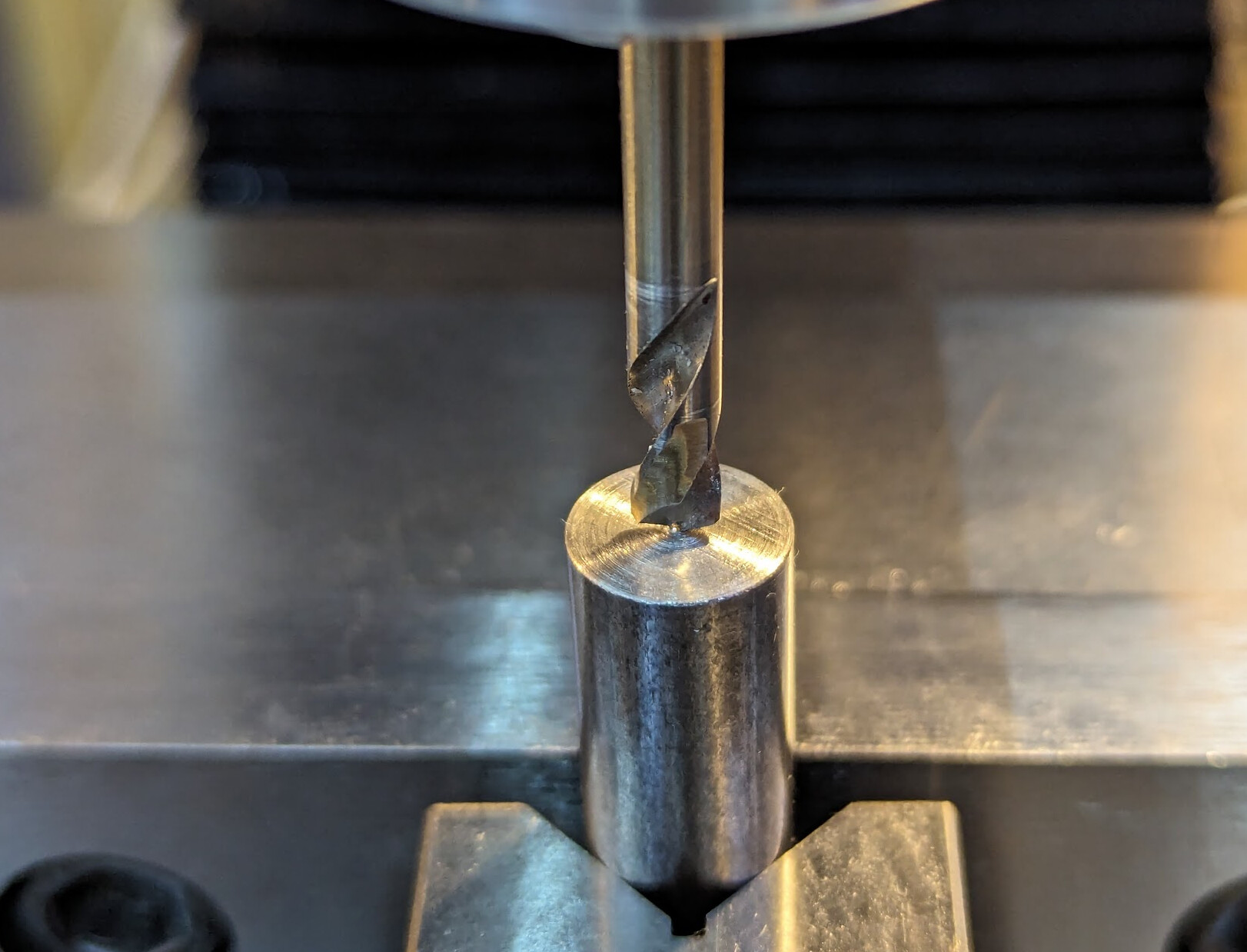
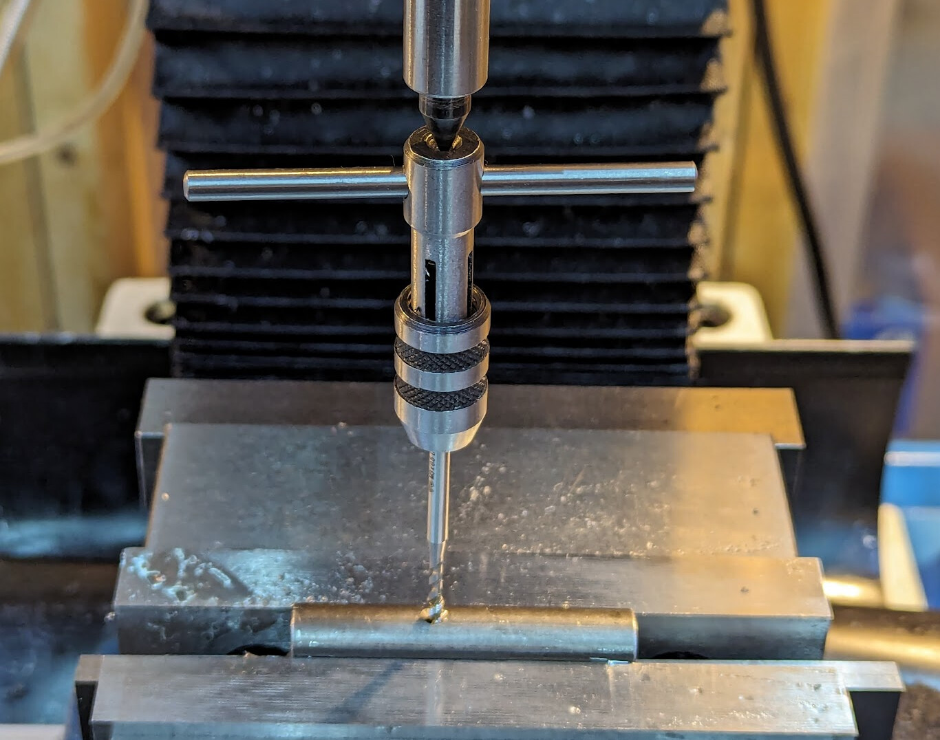
I had the idea that I could cut from the center at a 1° angle, making the front face the focus, and then just cut back as far as I wanted to allow for the broach to stick out. I cut off a chunk of 1/2" stock, put it in the drill chuck, and held rough sandpaper to it while it ran. It clearly marked where the center was. I tried to center punch it based on those markings. Then I set it up at a 1° angle and started drilling. With this stubby drill, I drilled only a short way in:
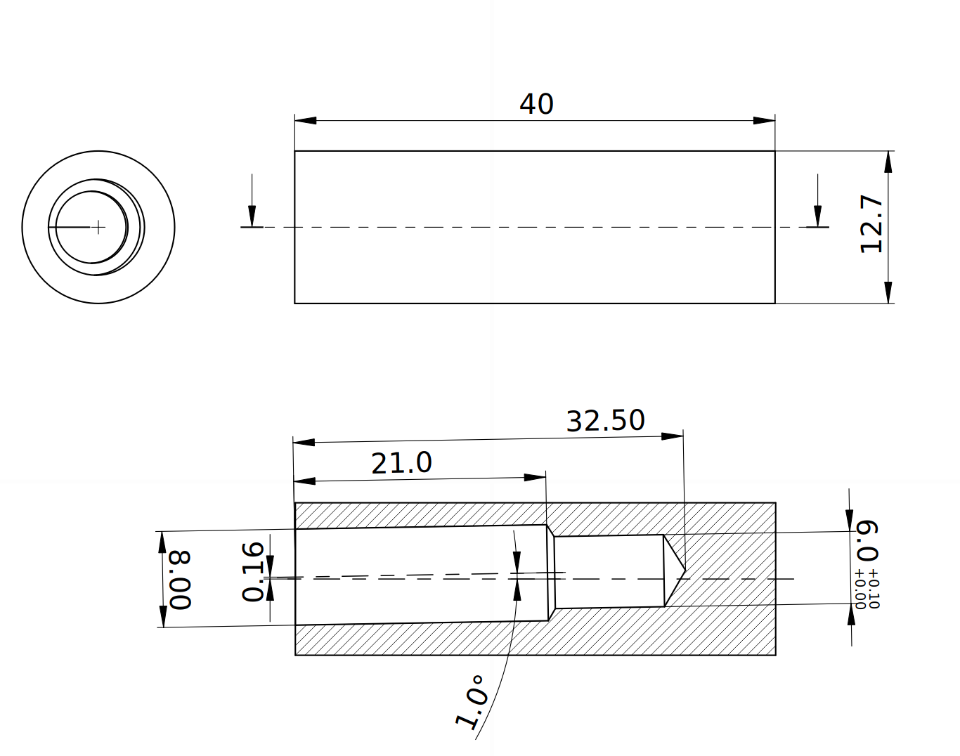
My initial idea was that this hole would be centered on the center of the part, and when I cut this off 8mm down the shaft, the hole would be centered 0.16mm off the center.
When I measured, however, failure #1 ended up being an accidental success. Instead of being centered, the hole happened to be about 0.16mm off center, and in the correct direction. So instead of drilling 8mm too deep and then cutting it off, I just drilled it to depth. 6mm twist drill 32.5mm deep, 7.9mm twist drill 21mm deep, 8mm reamer to the shoulder.
Then I put it on its side and drilled, countersunk, and tapped M3.
I found that way oil didn’t work well enough, so I switched to grease for everything. Grease to hold the balls in place, but also grease to lubricate the broach. And it turned very smoothly!
But after broaching a test piece, the broach came off in the test piece. It wasn’t hard to remove by hand, but the pneumatic assist didn’t work.
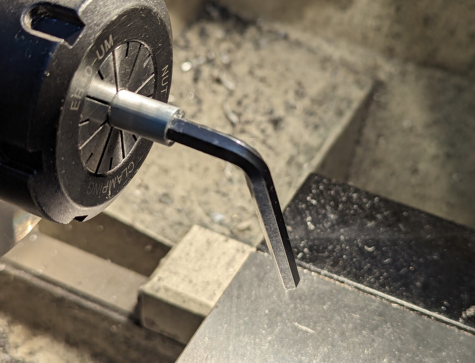
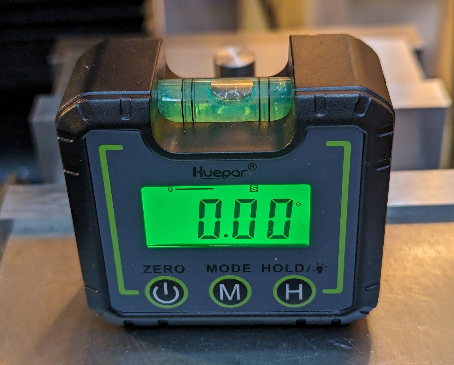
While I used a 1° angle block to set the angle, I checked whether a digital level would work. Yes, if you set up the shaft and v-block lightly in the vice, you should be able to tap it in close enough to work.
Referenced to the vise:
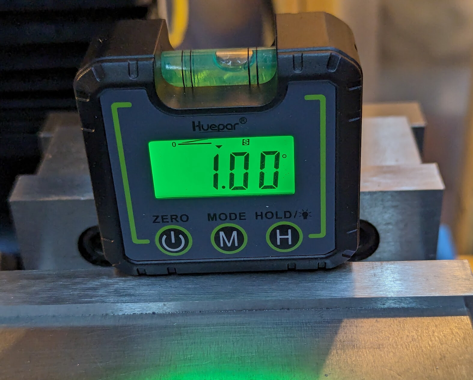
Stuck to the v-block:
Simplification from successful failure
The design got even simpler in the test. Just start the hole accurately, drill two different sizes into the end, insert bearings, and use.
Using only one bearing, the smaller diameter hole could be shorter by a bearing diameter; the idea is that the bearings being a loose fit, the top bearing is actually a few microns off center and can roll around, reducing friction. But it will work without it.