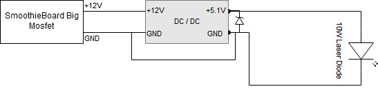
Has anyone connected an Endurance Laser (10W) to the Smoothieboard? I was wondering if the smoothie could control/power the laser directly using one of the Big Mosfets (see picture for a quick diagram). Would it be that easy or is there more to it?
I’m quite the novice so any help with wiring or config settings would be appreciated.
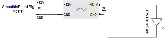
Followup question: I’ve been reading about protecting the Big Mosfets with a diode, but can only find information on which diode to use to protect the Small Mosfets. (I have a v1 board).
What diode do I need to protect the Big Mosfets? I have, for some reason, a 1N4004 laying around - would that work?
So… is the 1N4004 a good choice for the big mosfet? I’m not sure how to spec out a diode.
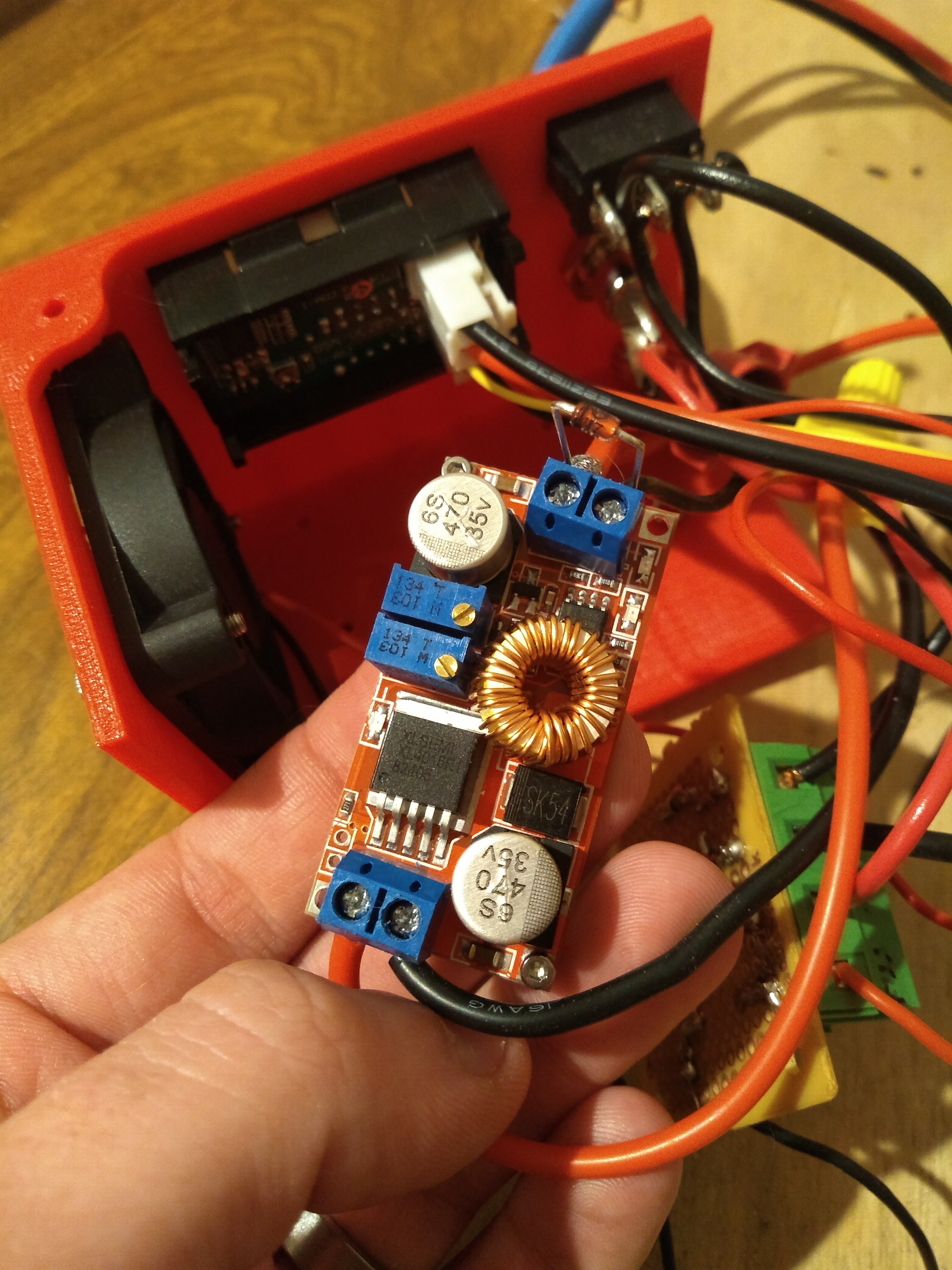
The “DC / DC” is a buck converter provided by Endurance Laser. It has two potentiometers to adjust the volt and amp conversion but right now its set to 5V output. I’ve attached a picture of it, as it doesn’t have a model number. It does seem to have an inductor hence the need for a diode.
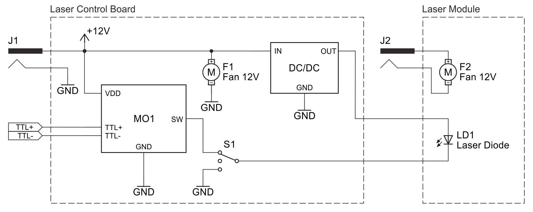
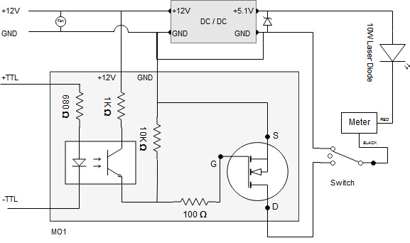
My goal is to replace their MO1 board with the smoothieboard - much simpler wiring. From my understanding the MO1 just provides TTL for switching the laser on/off. Instead I would just use the big mosfet and PWM to control the output power. I’m just not sure if that would actually work… diagram from endurance’s website below:
While a 1A diode would be fine for transients from a small inductor like that, it doesn’t matter, because your plan is not going to work well. The same inductor that makes you think about diode for protection is storing energy in a magnetic field and when you cut input power the magnetic field in the inductor is going to continue to provide output voltage for a while.
You can hook up the buck converter to the 12V supply as in their circuit diagram, and then use the “big mosfet” to drive another mosfet to switch the 5.1V output from the buck converter. This seems like a boondoggle. Is there really not a free output pin you can use to directly drive an external mosfet to switch the 5.1V supply? If not, I would consider just connecting the gate from the internal “big mosfet” to an external mosfet that is switching the 5.1V output from the buck converter.
Usually n-MOSFETs are cheaper and more efficient than otherwise equivalent p-MOSFETs so they are interrupting the ground side, roughly as S1 in the schematic you are linking.
This is more an electronics question than a smoothie question though!
I was wondering where to post this question. I hoped there would be enough electronic expertise in the Smoothie forums to help . I really appreciate the feedback, I’m learning as I go on this electronics stuff…
So I made this diagram for my own understanding of what Endurance was trying to do with the MO1 board. It sounds like what you just described when you asked:
Is there really not a free output pin you can use to directly drive an external mosfet to switch the 5.1V supply?
You think this (the MO1) is the best solution? I don’t think I understand why using the MO1 would alleviate the issue you described with the inductor continuing to produce current. Wouldn’t both solutions have this problem since both rely on the buck converter?
If I go with the MO1 (if my understanding is correct) I hook the +12V up to constant DC power (not from the big mosfet), then the TTL is hooked up to a PWM on the smoothie and that will control the laser power. Then within the config just make sure I set the correct PWM pin in the laser module.
I was just hoping that Smoothie could provide a simpler solution via the mosfets to control the laser power. I figured I have a Smoothie - might as well use it!
(The funny thing here is that I don’t personally have a laser or smoothie…)
The 12V supply feeding the buck converter has inductors of its own and doesn’t need that protection. The fan you show also has inductors (electromagnets are how fans work, after all). It’s very common to power them directly from 12V power supplies for fans that should always be running while a device is turned on.
The MO1 is using an opto-isolator for the PWM signal which makes sense, and then the opto-isolator switches the gate in the MOSFET in the MO1. So the “simpler” version would be… building the MO1 yourself, possibly without the opto-isolator but frankly it’s a good idea and super cheap; the opto-isolator is a “popcorn” part (I bought 50 or 100 because it was about the same price as 1, last time I ordered any).
So I’d definitely suggest that go with using the MO1 they provide rather than trying to do without.
If it’s a separate part that you want to not order, then the MO1 is the equivalent of the MOSFET boards that you can buy extremely cheaply for switching DC-powered heated beds for printers, that people sometimes use to run the heated bed off a separate (sometimes higher-voltage) supply. By way of example only and not endorsement or otherwise, this kind of thing:
If you look at the pictures there, you’ll see that it has an opto-isolater and a mosfet. In other words, it’s essentially the same thing.
So… I actually did build my own after I accidentally ruined the one they gave me haha. It really helped my understand how it worked! It would have been a lot easier to just buy one of these bad boys though haha (but I learned a lot, so it is still a win to me)
Once I got a better understanding of how it worked I was thinking of ways to improve and simplify my setup and thought that maybe the Smoothie could already handle it. I suppose I’m still not fully understanding why Smoothie’s big mosfet isn’t a suitable replacement, but I will re-read your posts until it hopefully clicks. Do you mind if I direct-message you with more electronic questions if they arise? I really appreciate the help and admire the intuition some of you guys have.
And if anyone else has opinions I don’t want this post to be a thread stopper - please respond!
I prefer keeping questions in public threads where everyone can benefit. General electronics questions would make more sense in the Electronics category, though. Keep in mind I’m a hobbyist with limited experience just in the past few years without it being my major hobby. I’m no EE.
If the smoothie big mosfet were switching 5V it would possibly be just fine to connect the laser directly, no buck converter or MO1, for all I know. But since it’s not the point is moot.
I would just drop the MO1 board and connect the - side of the diode directly to the - pin of the big mosfet on the smoothie board. This mosfet does exactly the same as the MO1 board, it ties the - pin to GND when fired.
WARNING: You must make sure the - pin of the laser diode is NOT connected elseware to gnd (via the machine rails, case…)!