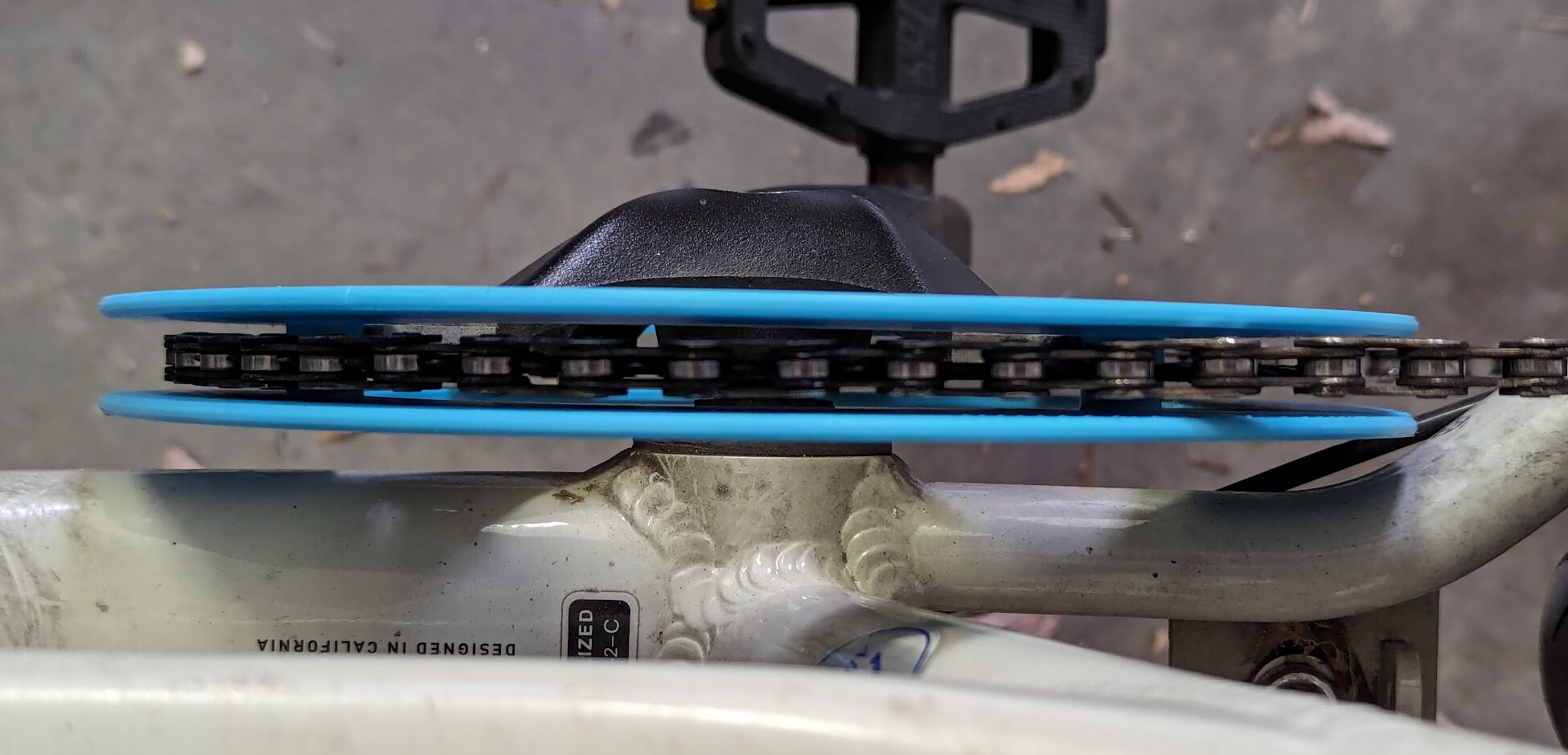
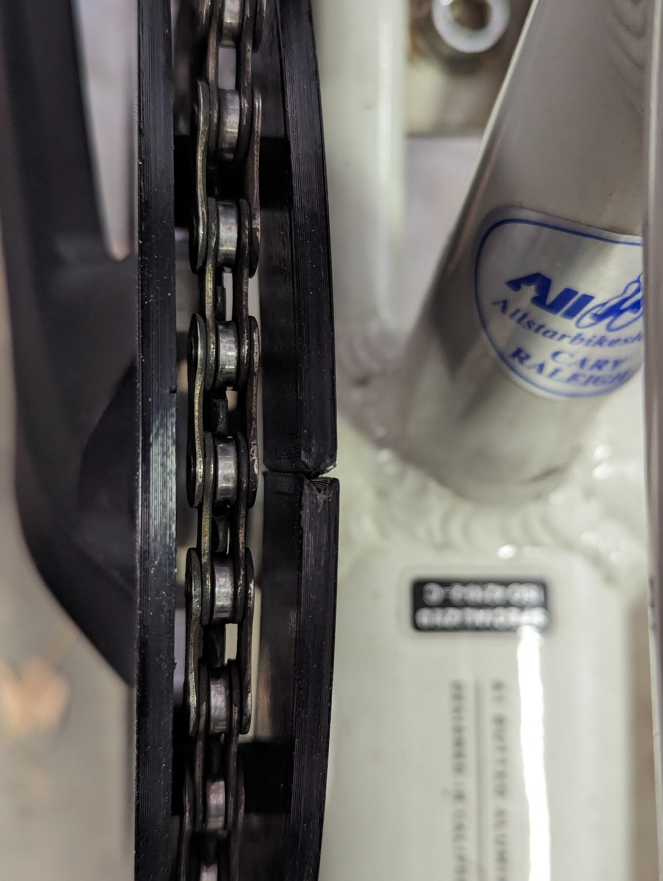
One of my kids has a Specialized bike, and the front sprocket came with a plastic chain guard with two pieces surrounding the front sprocket to keep clothes away from the chain. It broke, and internet forums apparently say this is common because it’s just held in place with plastic pins, and a pain to replace because you have to remove the crank and sprocket to get the inside ring in place. The chain guard was nice because it avoided the need to wear pants clips all the time, and this bike is a constantly-used commuter bike.
I have a 3D printer and can drive FreeCAD — could I maybe help with this? Maybe make the inside ring in two pieces so that it can be easily installed without removing the crank and sprocket?
TL;DR:
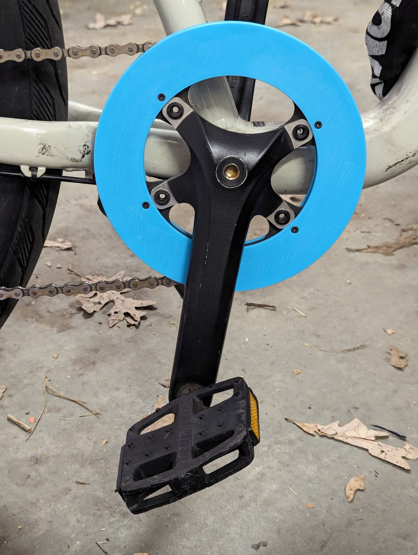
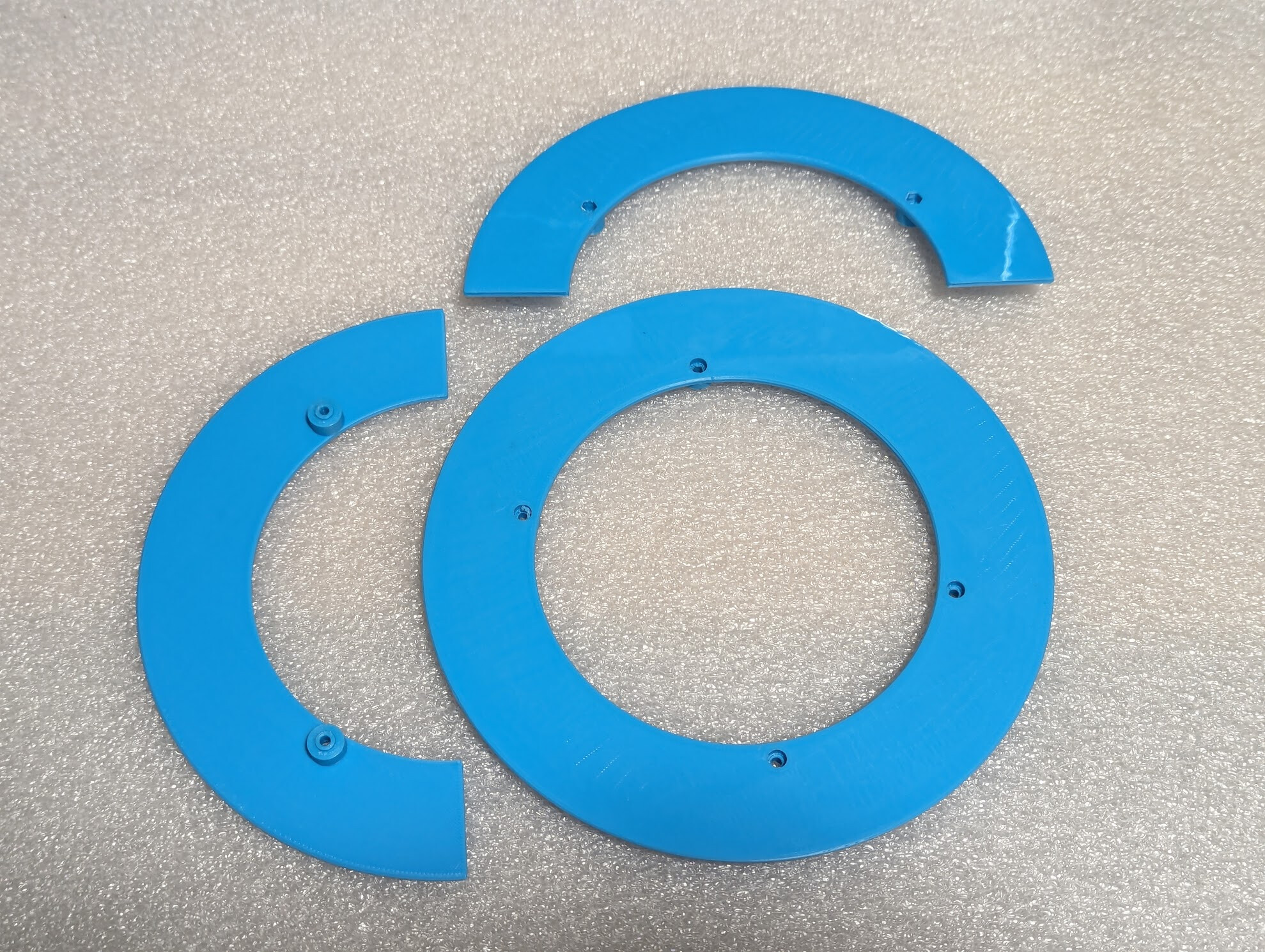
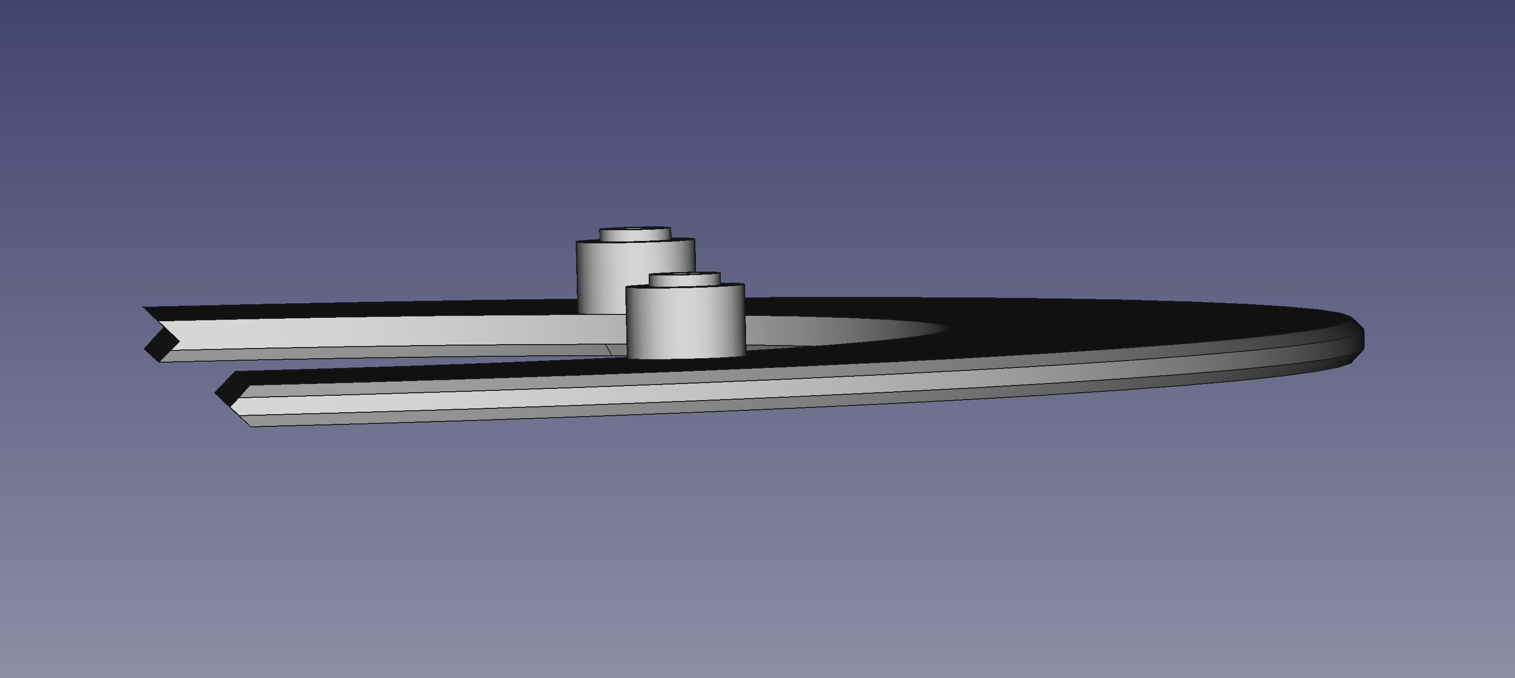
Prototype
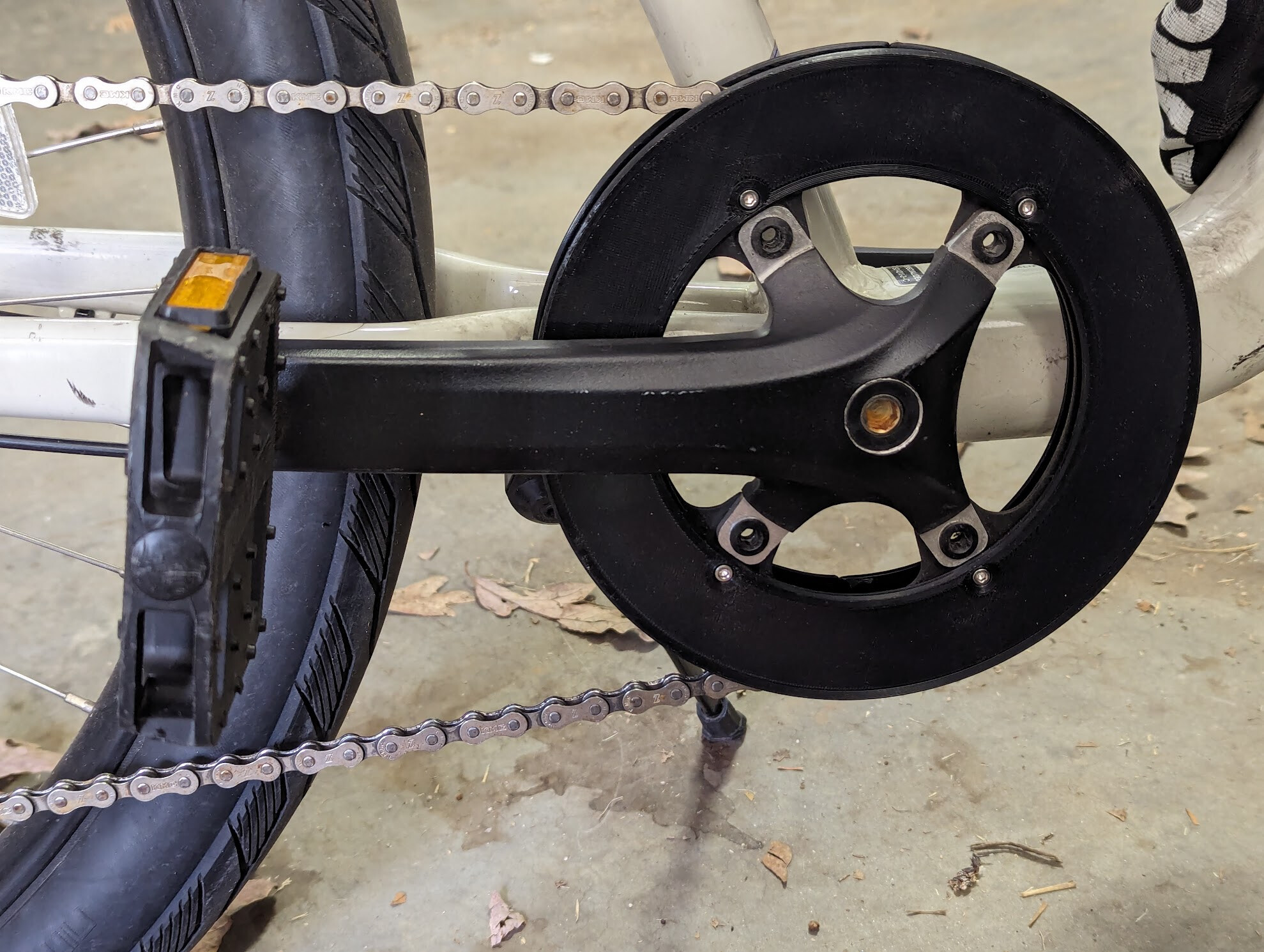
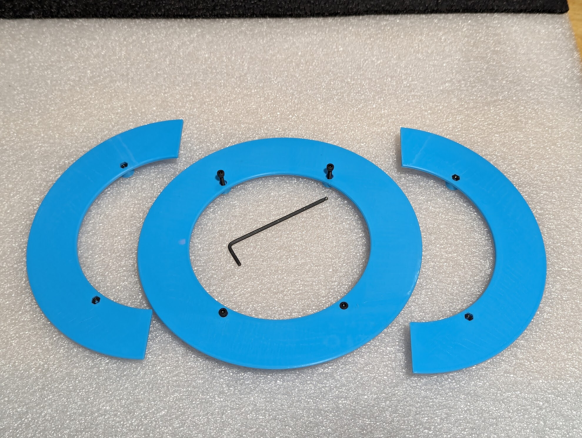
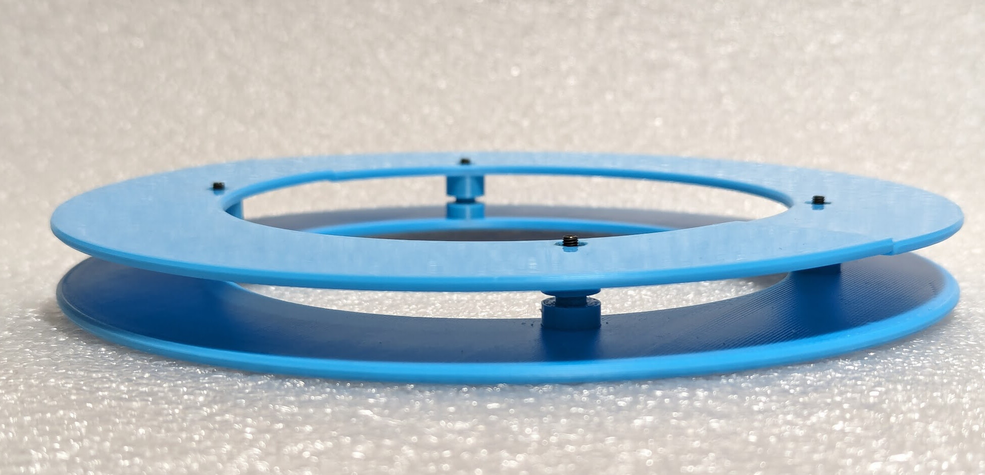
Final revision
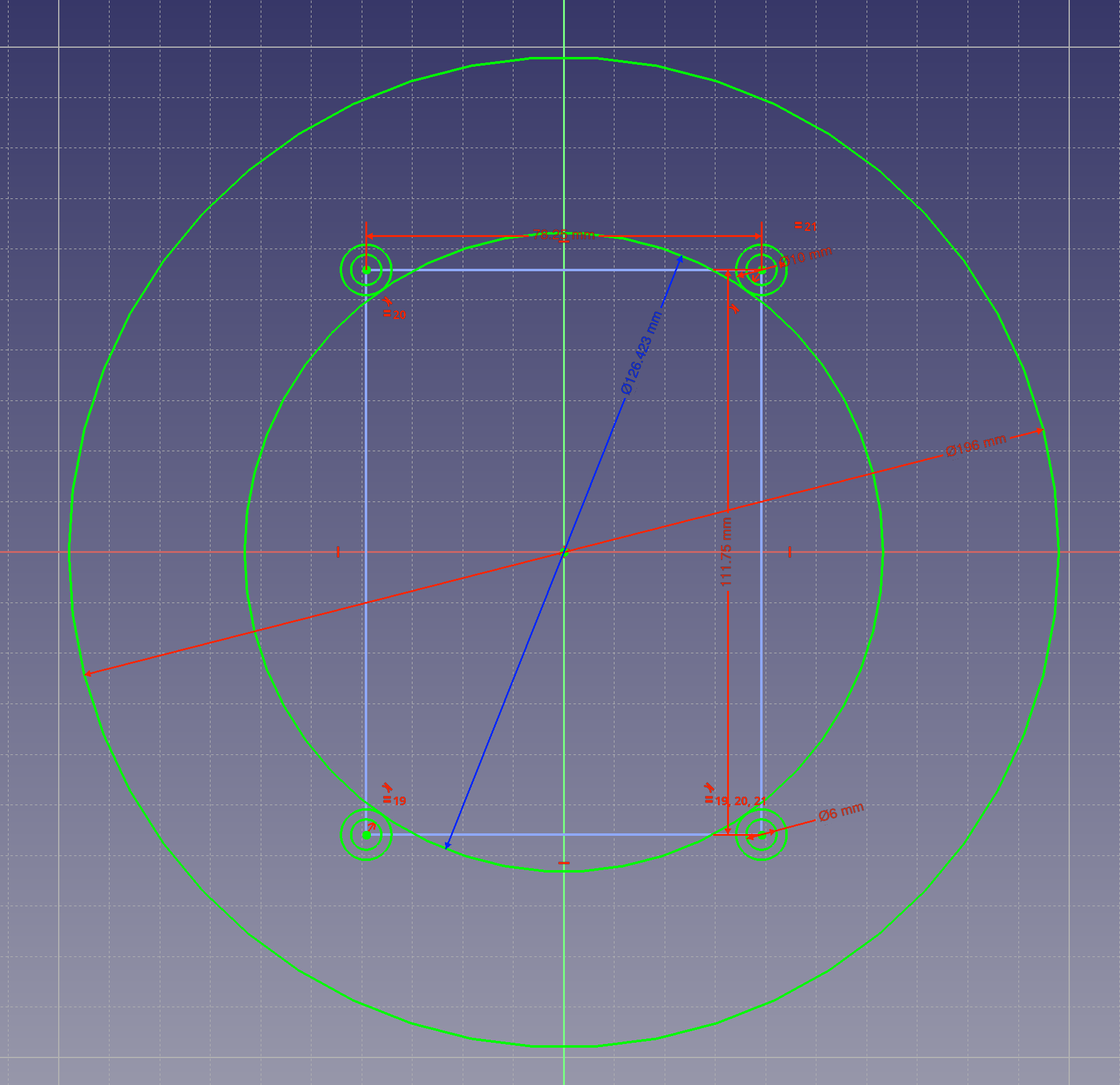
We measured the hole pattern for the four holes. I used a master sketch to model the inner and outer perimeters of the loops, and the location of the holes. 6mm (definitely not 1/4"!) holes, with centers about 78.25mm (suspiciously close to 3") apart on the narrow side x 111.75mm (suspiciously close to 4.5") apart on the wide side.
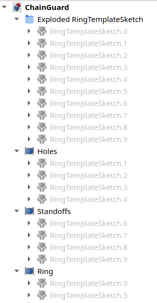
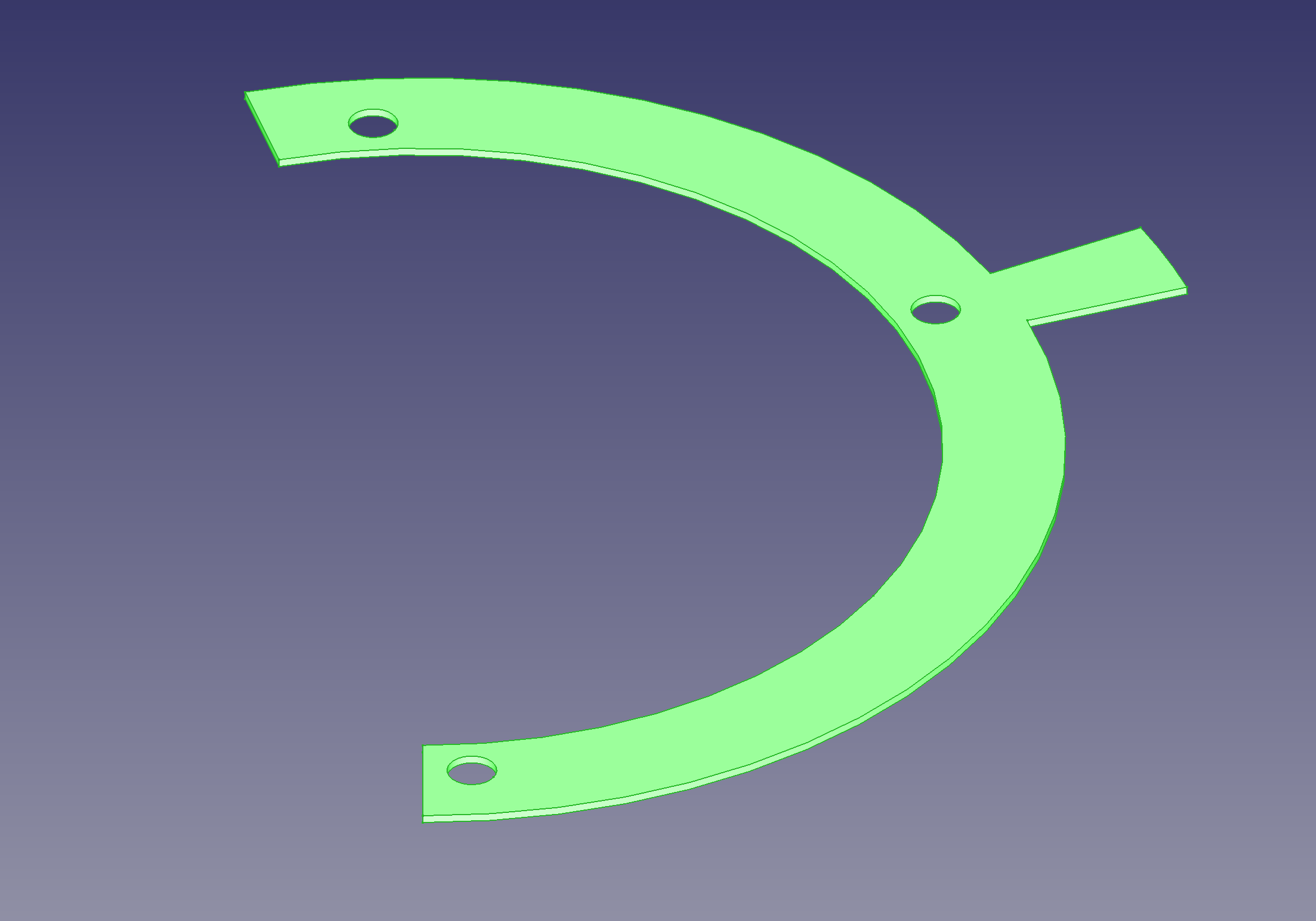
I exploded the sketch (thanks Mang0Jelly for the tutorial) with Part → Compound → Explode compound, then Part → Compound → Make compound to group the individual elements into logical supports named Holes, Standoffs, and Ring, which are the basis of the parts:
I printed a test piece with just enough plastic to validate the hole location and visualize the size of the rim, using M6 screws to locate it because the holes are 6mm. Three holes are enough to test both hole offsets, and one flag enough for the size of the outer perimeter.
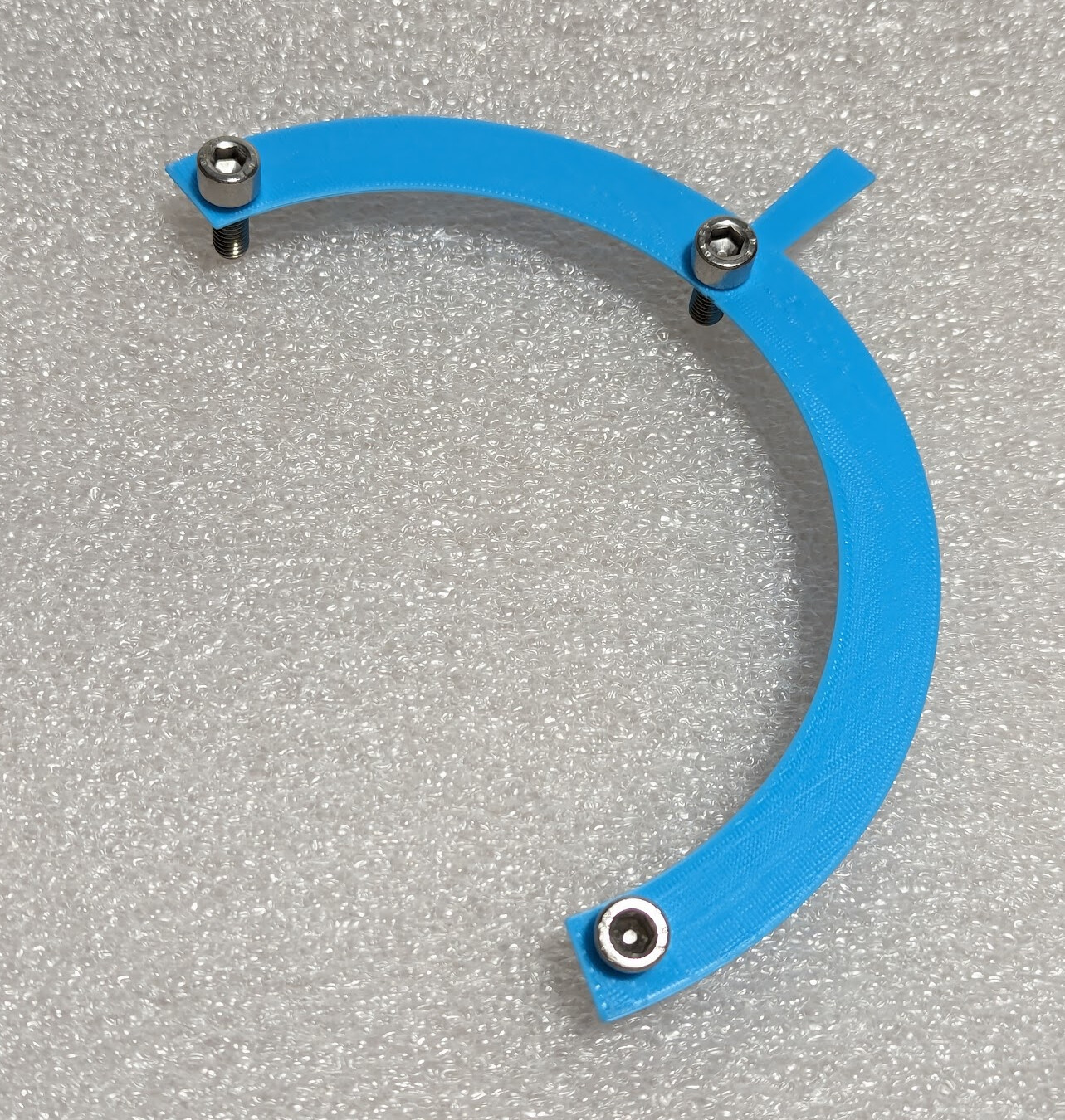
Got a little lucky and nailed the hole location on the first try, and decided that the rim should be a bit shorter.
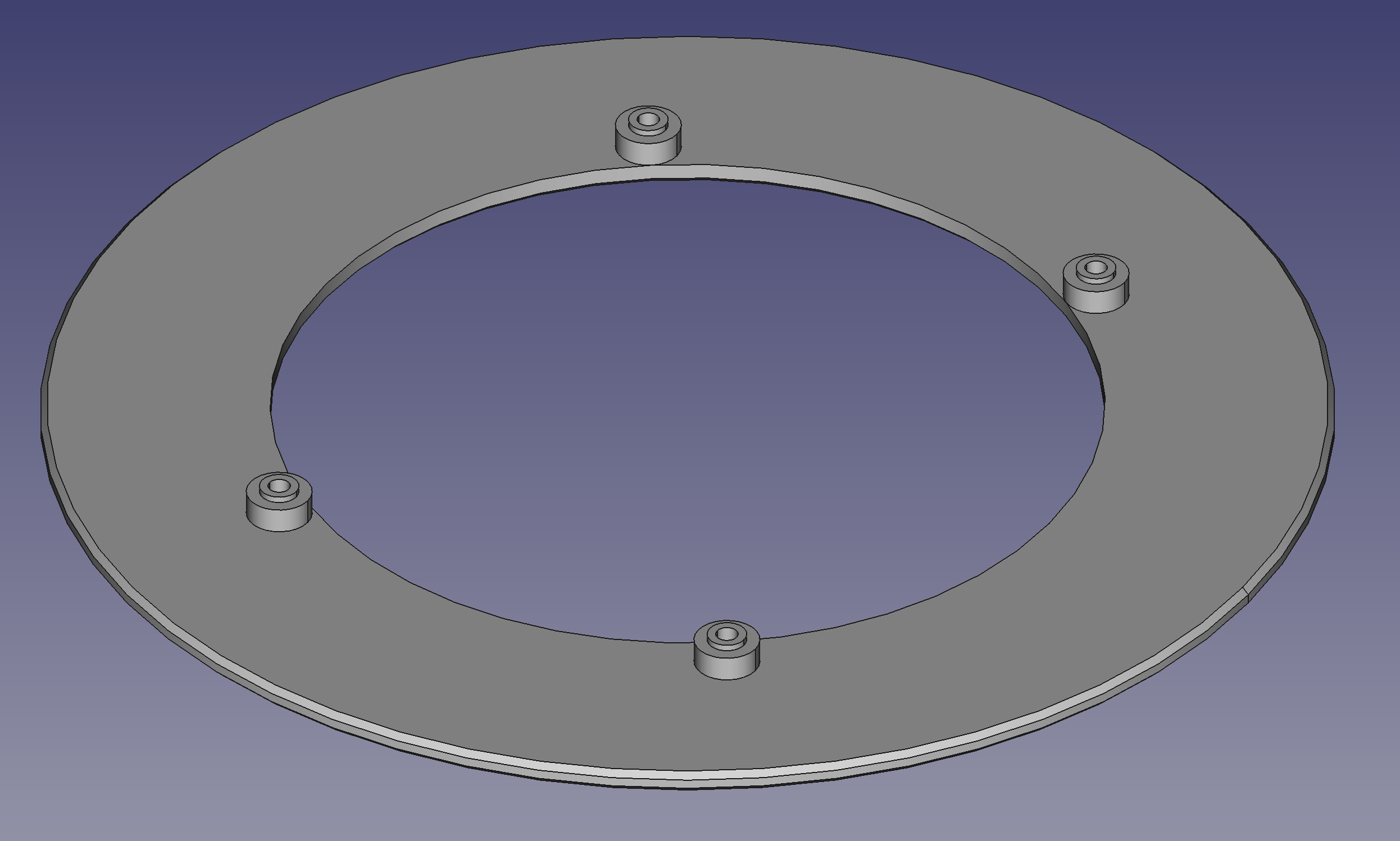
Then I used subshape binders from sketches to make both rings such that as I make adjustments, they will apply to both inner and outer rings.
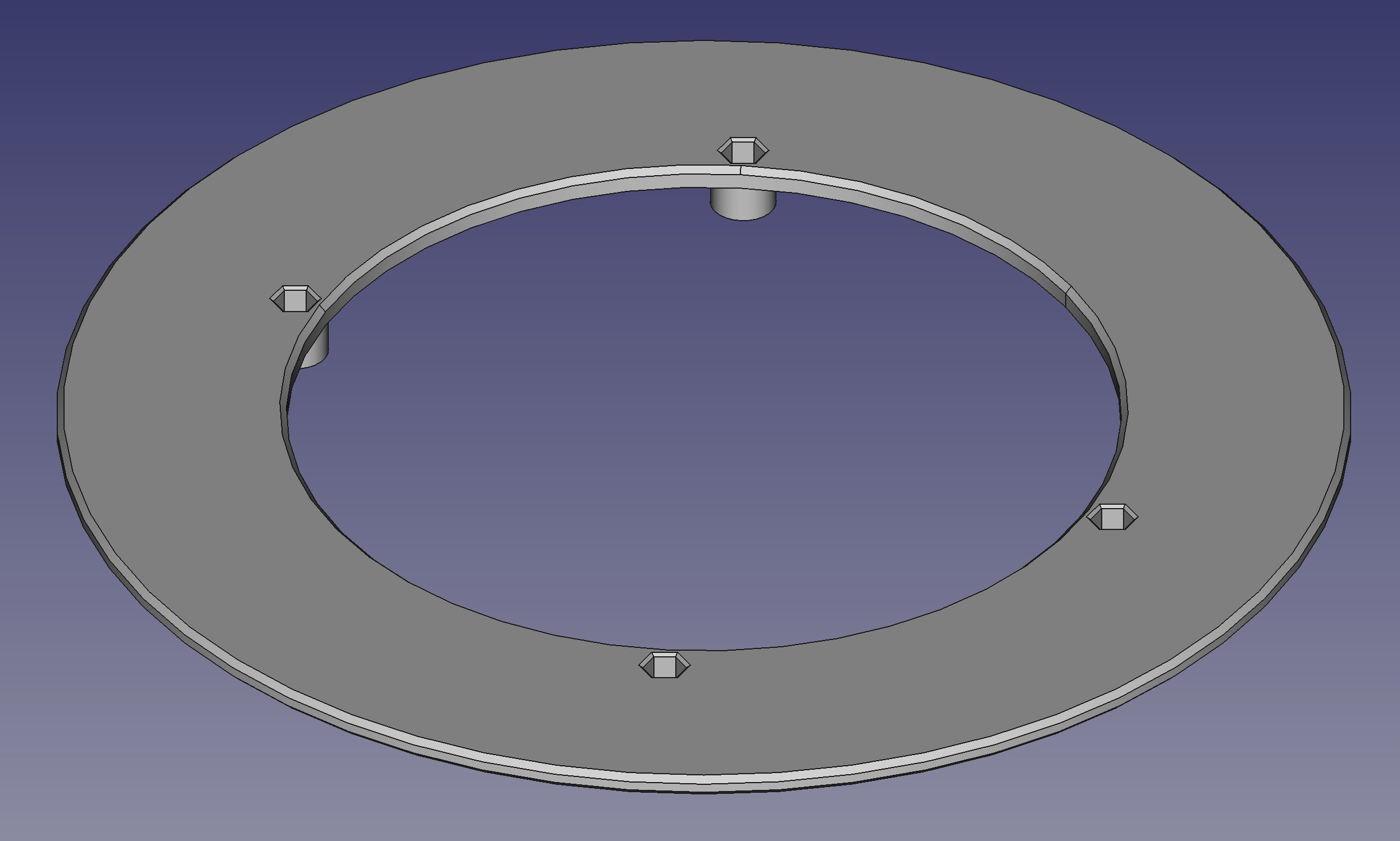
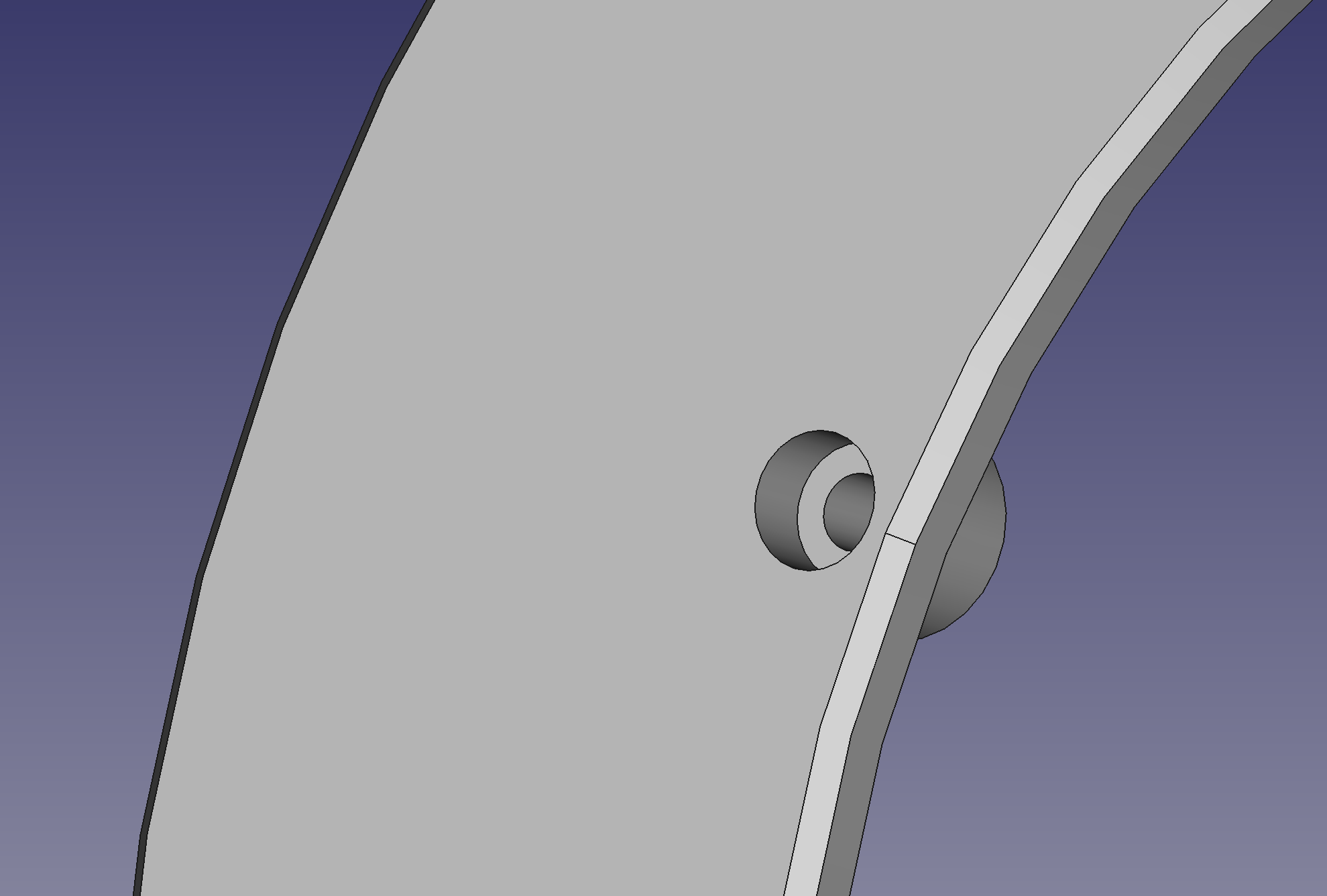
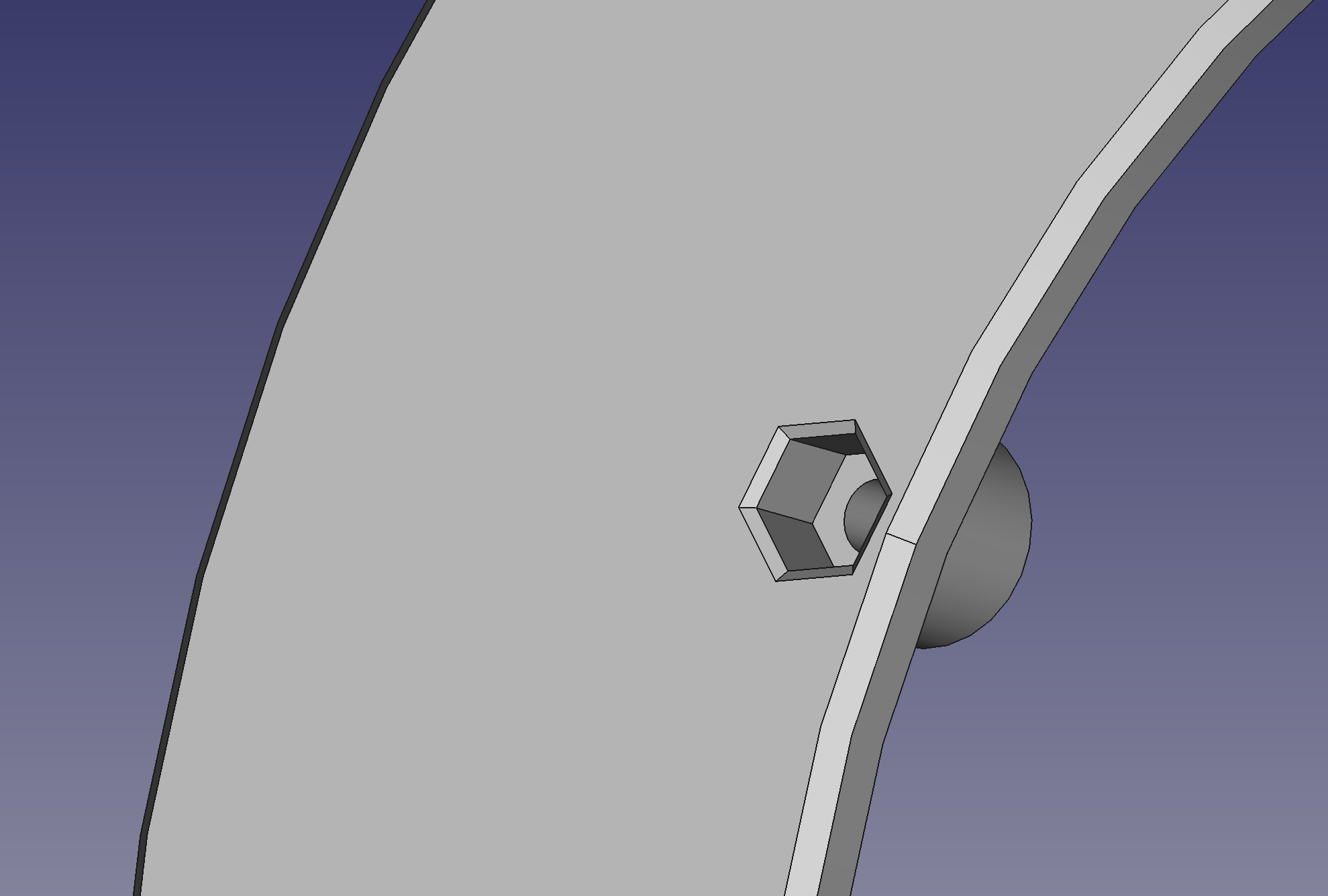
The inner and outer rings are almost identical. The outer ring is counterbored for an M3 cap screw head, and the inner ring has chamfered hex insets for an M3 nyloc lock nut; the standoffs are 2mm taller on the back to accommodate the chain path.
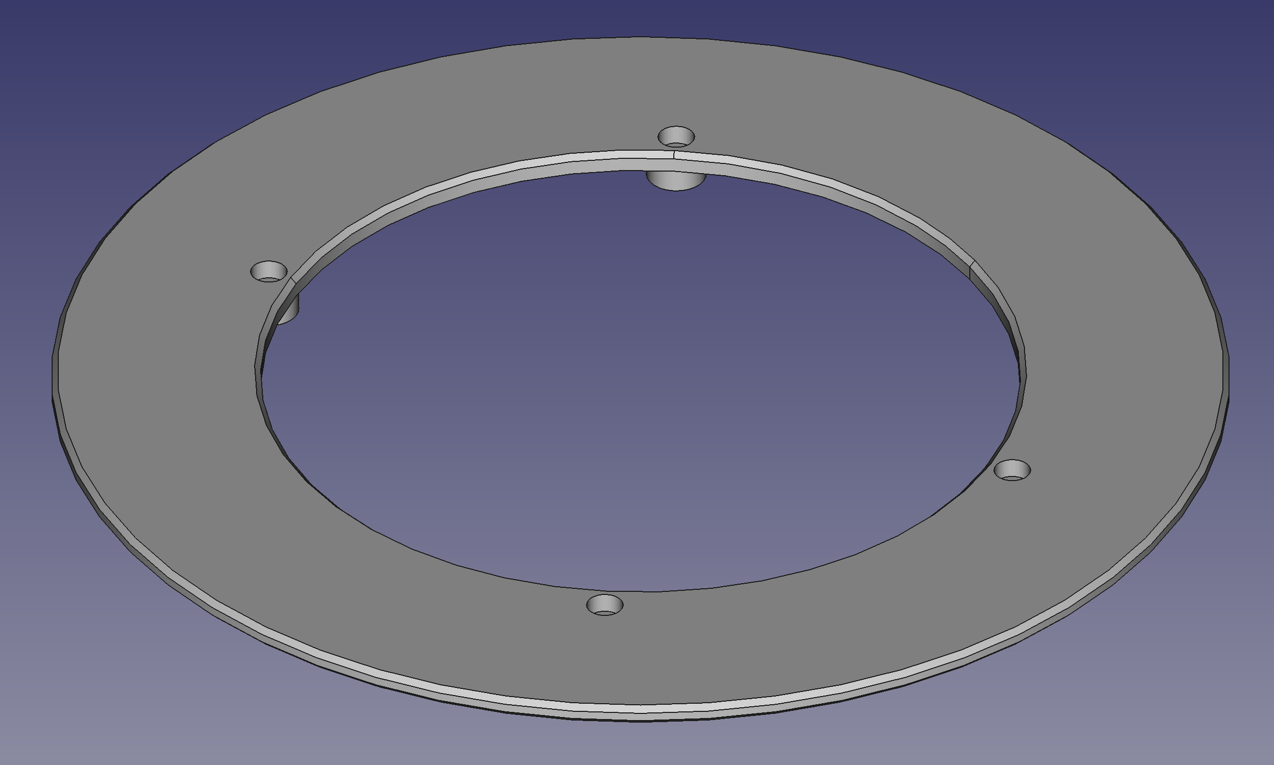
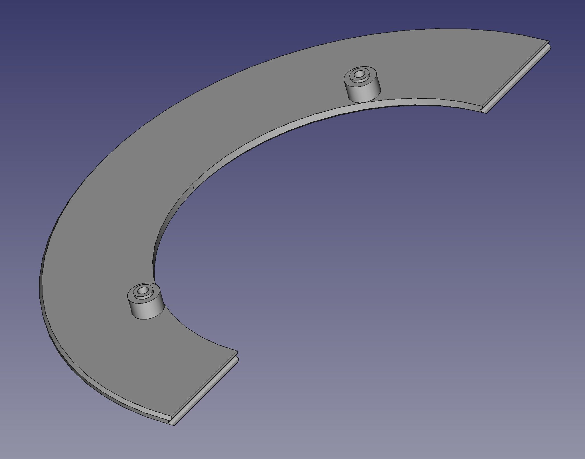
To install it easily, I made a clone of the back ring, cut the clone in half, print two halves, and added a groove to hold a length of filament with glue between the halves to hold them together V-grooves to mesh the halves together. In testing, not having some way to hold the split together looked wonky. I modeled it that way in case someone else wanted to use this to print a single inner ring and remove the sprocket to install it.
The final version won’t be printed in nice bright blue ABS, by request. I’ll either use plain black ABS, or will bust out the hardened nozzle and print some black carbon-fiber PET or black glass-fiber ABS. ABS has the advantage that I can use ABS glue made from ABS filament and acetone to glue the inner ring halves together, but they don’t really need to be glued together, and they can be removed if they aren’t glued. CF-PET would be the toughest engineering plastic I have…
But the light blue ABS prototypes made it easier to take pictures to show here. ![]()
I printed these with supports on the build plate only.
The FCStd file is meant to be able to be tweaked for other similar sprockets with different hole size and spacing. If you have exactly this sprocket set, and do not want to remove the sprocket, you can just print the outer ring and two copies of the inner half ring. If you are removing the sprocket, you can print the full inner ring.
If you have a similar sprocket, I tried to make the FCStd file easy to modify. Ask if you need help modifying it!
As designed, this uses 4 M3x16 cap-head screws and 4 nyloc nuts.
ChainGuard.FCStd (280.0 KB)
ChainGuard-InnerHalfRing.step (173.5 KB)
ChainGuard-InnerRing.step (251.3 KB)
ChainGuard-OuterRing.step (119.5 KB)
