Pnot sure if this is the correct place to post this. I am running Grbl-lpc on an mks sbase. There is not much documentation on wiring relays for mist and coolant. In my case these would be air assist and exhaust on a laser cutter.
Are the sbase pins below the same voltage as the power supply or 5v? I assume it’s the same as the power supply since they are extruders and in my case 12v.
So would I connect the positive terminal or the negative terminal to the signal portion pins the double relay board?
You are using the E1 and E2 heater connections, which are switched by MOSFETs on the board (Q3 and Q2).
Look at page 15 of the schematic. You will see that P2.6 and P2.7 control n-MOSFETs which switch the negative terminals; the positive terminals are supplied VIN1 (full 12V-24V input voltage as you supply, protected by fuse F2; see page 3). The n-MOSFETs are protected by diodes D12 and D13 and so should be fine for directly switching relays. (If they didn’t have diodes, you would have to add a diode across the terminals to shunt back-emf when turning off the relay.)
You can see the diodes and MOSFETs on the pin diagram:
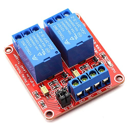
You mention “signal portion pins the double relay board” so I’m guessing you have some relay board that was intended instead to work at logic level. You might want to post links and pictures for that specific board. If your board was intended to supply a positive signal and has a shared ground connection between the pins it won’t do what you want. So to give good advice on how to connect it, you’ll need to provide more information.
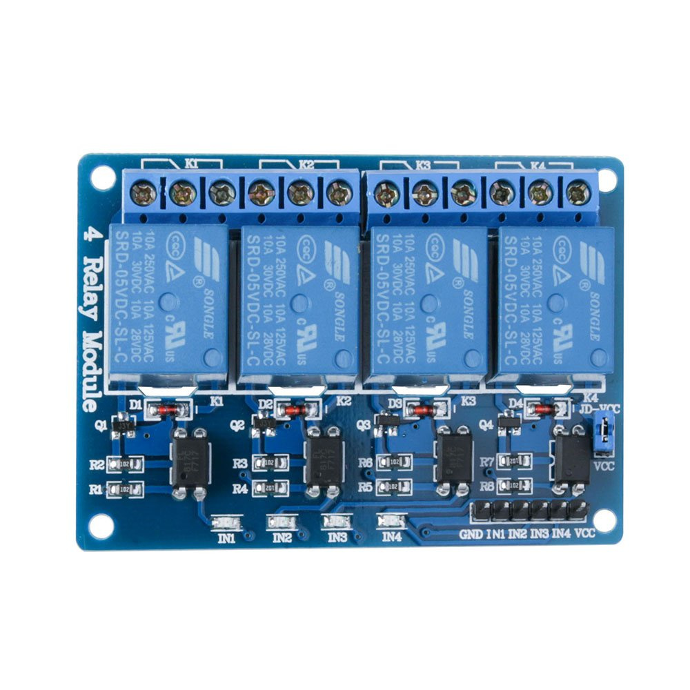
I have DC+ and DC- connected to 12V the power supply directly. I have In1 and In2 currently connected to the positive terminal of pins of E1 and E2 and the relay remains active. I did also buy a 5V 4 relay version if that would work out better?
Both of the boards look to me like they expect signal relative to a common ground (labelled DC-). The E0 and E1 terminals on the SBASE could directly drive a relay without the intermediate logic-level circuitry on those boards. It doesn’t show any obvious place to connect directly to the relay on those boards. If I were doing this, I’d just be connecting two relays, one each directly to E0 and E1, and skipping the signal board.
It might work if you set the black jumpers to L, then connect:
either one of the E0+/E1+ positive lines on the SBASE to DC+ on the relay board
GND to DC-
E0- to IN1
E1- to IN2
two 10K or so resistors (“pull-up resistors”):
one from DC+ to IN1
one from DC+ to IN2.
Then when you “turn on” E0 or E1, you are really connecting to GND, pulling the voltage on the IN1/IN2 signal ports low, to turn on the respective relay.
@donkjr — does that make sense to you? See anything I’m missing here? I haven’t played with any of these relay boards, so there could easily be something I don’t know about them, and figure you are likely to have a clue here. @Jonas_Concepcion note that I’m a programmer not an EE and I’ve let the magic smoke out of a few boards…
@Jonas_Concepcion This is where product links would have come in handy! Looks similar to this:
That lets me see more higher-resolution pictures (though still not a schematic) and that one looks like it has a 2.2K resistor on board for each channel, which is a pull-up resistor if you choose the L side to jumper, and a pull-down resistor if you choose the H side to jumper.
Thanks guys I’ll give this a go this morning. The electrical talk is foriegn to me. I have have an art background and play an mechanical engineer at work.
I didn’t realize these boards had much more going on with them. I just liked that the relays we’re mounted and had screw in connections so I would not have to solder anything.
There was a bug that caused M9 to only disable M7 but not M8. This has been solved in the source, but I did not have time to recompile all the bin files yet. See commit:
Thanks. So I can just replace coolant_control.c in my set of files? I do plan to compile my own version for this machine since I have somewhat of an awkward homing setup.
By the way:
I have added a compile switch #define HOMING_FORCE_POSITIVE_SPACE to change homing behaviour so that the origin (0/0) is always set at bottom left, independent of the homing location.
For example: If you home to X+ and Y+ and have set $130=300 and $131=200 the position after homing will be set to 300/200, which makes bottom left the origin 0/0.