Or you could use a micrometer screw like this:
https://de.aliexpress.com/item/4000709718003.html
Bigger, $20, and two months of shipping vs. print it now? And in that linked article, Mark warns that a lot of cheap micrometer screws aren’t actually differential screws, even when they say they are. He’s so often right about things…
I’ll be honest, the repeatability of a standard endstop is really actually pretty good from my testing. And with software z offset, and babystepping you can dial first layers into fractions of a millimeter. I really the differential screw adjustment in theory, and the mechanics of it are perfect. But I’ll be honest it seems like a lot of mechanical work for something that can be solved more easily. Then again I’m always one of those people that ascribes to, make as simple as it can be made… but no simpler.
The other item I worry about is cantilevering out a precision mechanism. Are you losing the precision you gain by having it on the end of a cantilever.
Anyway it goes I really like following the progress. And I’m always excited to be proven wrong. there’s nothing like learning something new and better, by saying it doesn’t matter and then being shown how much better it works. There should be no pride in engineering, just the facts ma’am, the proofs in the pudding.
Are you going to force me to be honest? It was an excuse to use the lathe!
I did choose the 2060 instead of 2040 for the cantilever beam after checking out the statics on deflection. 
Edit: oh, the cantilever of the plastic arm holding the flag? I don’t think it matters because it’s static, so even if there is meaningful deflection, the deflection shouldn’t change. I don’t think I’m losing precision in any meaningful sense. I can test with a dial indicator of course.
But ultimately this is an experiment in “what can I do with stuff lying around the house” from the start.
Hey if I had to lathe I would be finding excuses to use it all the time too. I’ve got my CNC router at the house which for flat parts in aluminum is a dream. But really a proper bench top mill or bench CNC mill and a lathe are two items that I desperately want. But for some reason the wife wants the kids to be able to go to college
2 Likes
Tonight, I worked on a few projects for this printer.
- Checked the standoff mounting holes that I put loctite into last night. Two of the holes seemed to work well, one less well, so I just did the same thing one more time on the third hole and will check again tomorrow.
- Scribed lines on the bottom of the bed to center the heater.
The heater is a 500W 120V 200mm x 200mm heater on a 224x275mm bed; I have a theory that this is OK because aluminum conducts heat well. (I have a 300x300 mm heater on my 330x330mm bed on the corexy and heat doesn’t drop of precipitously in the outside 15mm.) 500W is a lot for that size, but it was what I got cheap. - Polished and cleaned the underside of the bed.
- Mounted the heater on the bed
- Put a 192⁰C TCO on one of the heater wires to the bed.
I used crimp connections; soldering a TCO seems like a bad idea for multiple reasons. Labeled the bed 192⁰ so I remember later which TCO I used. - Scribed lines for the locations for my kinematic mount feature blocks.
-
Experiment I used RTV silicone as an adhesive to hold the kinematic mount feature blocks to the bed.
I discovered that the scribed positioning lines were useless when the RTV squished out and covered them, so I had to use calipers to position the blocks correctly. If I messed up, I’ll end up with a crooked bed.
Each block has a 15mm x 10mm contact area touching the bed. I left them clamped to the bed overnight to set. (If this doesn’t work, I can re-do it with JB Weld but that’s rather more permanent, so if I end up needing to recreate the feature blocks it would be inconvenient.) - Ran a bead of RTV silicone around the edge of the bed heater, as recommended by Keenovo
- Put a huge bolus of RTV over the TCO, then used duck tape to hold it down to set.
- Sprayed water mist on all the RTV to ensure it sets.
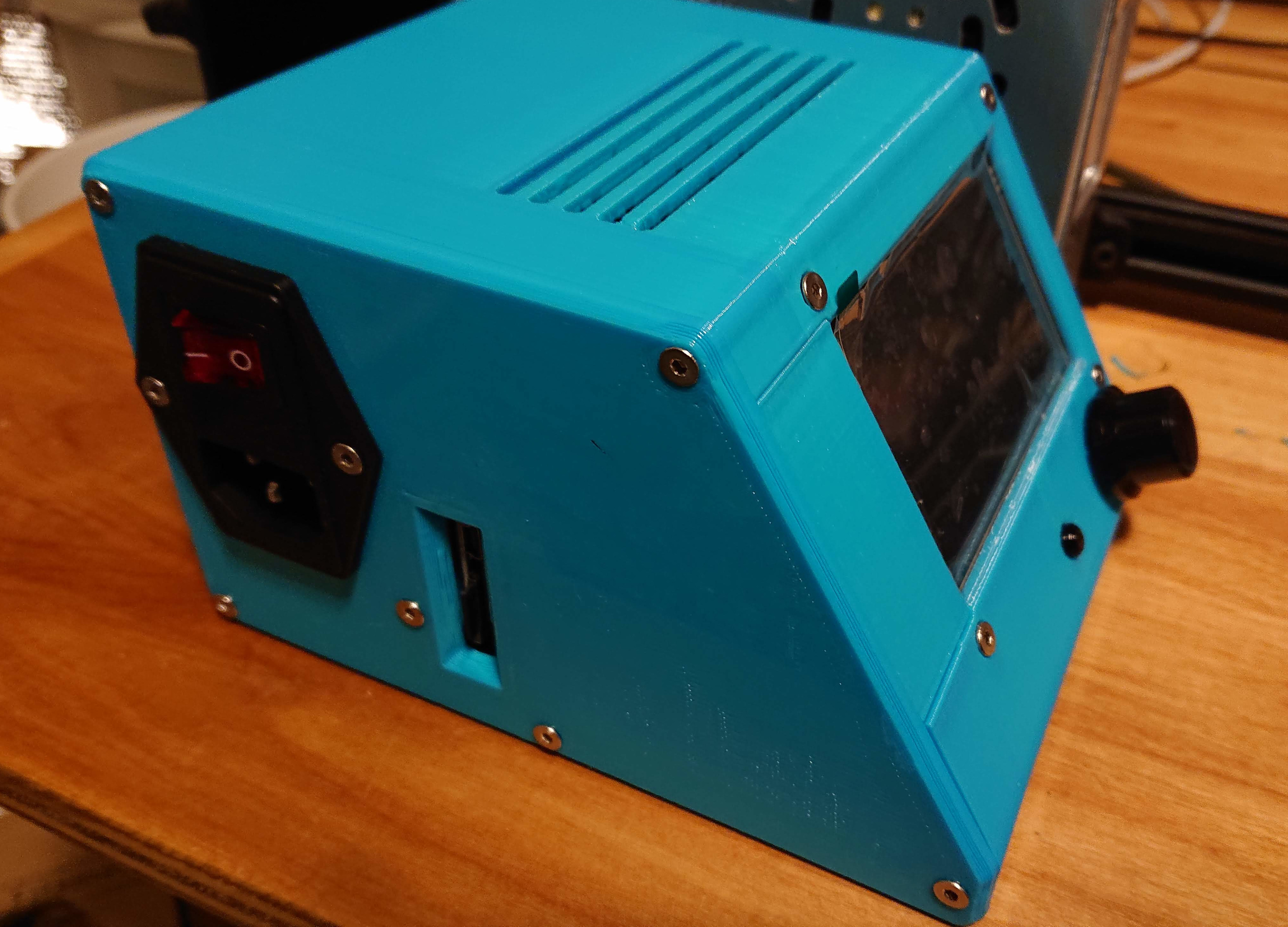
Then I moved to working on the electronics case.
- The longest pan head hex socket M3 screws I have were only barely long enough to attach the display. Holding the M3 nuts in place at the inside of the assembly took some creativity.
- With the display in place, the reset button works perfectly, it couldn’t be better!
- All the other screws fit fine. I used pan head hex socket M3 screws of various lengths everywhere, and it looks beautiful to me.
- The USB ports, microsd, and sd slots all are accessible and function well.
I didn’t do any wiring. I’m hoping I don’t have to remove the display to attach the wiring to it, because holding those nuts in place was tricky.
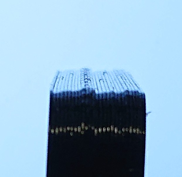
Here’s the reference kinematic feature block:
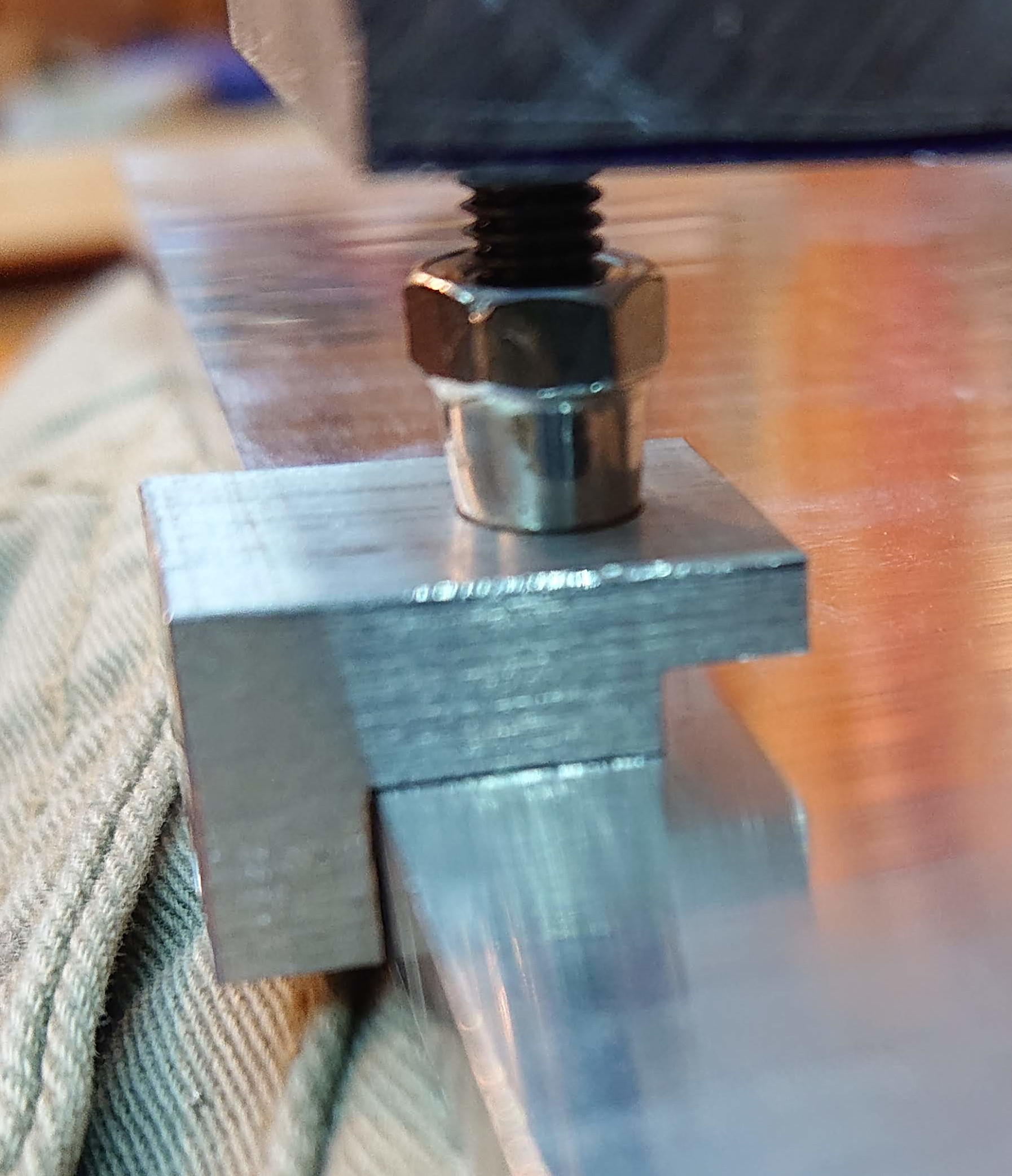
Not much extra room on that screw (sorry, bad picture):
Looking better in real life than in this picture, again without great color balance:
The slots are too long and bend easily. They are probably going to break some day. I should probably have done what I’ve done with some designs in OpenSCAD where I’ve patterned hexagons; those can print vertically and look really nice without support, and can be very strong. But it’s not important enough right now to print another 1/3kg or so to change.
4 Likes
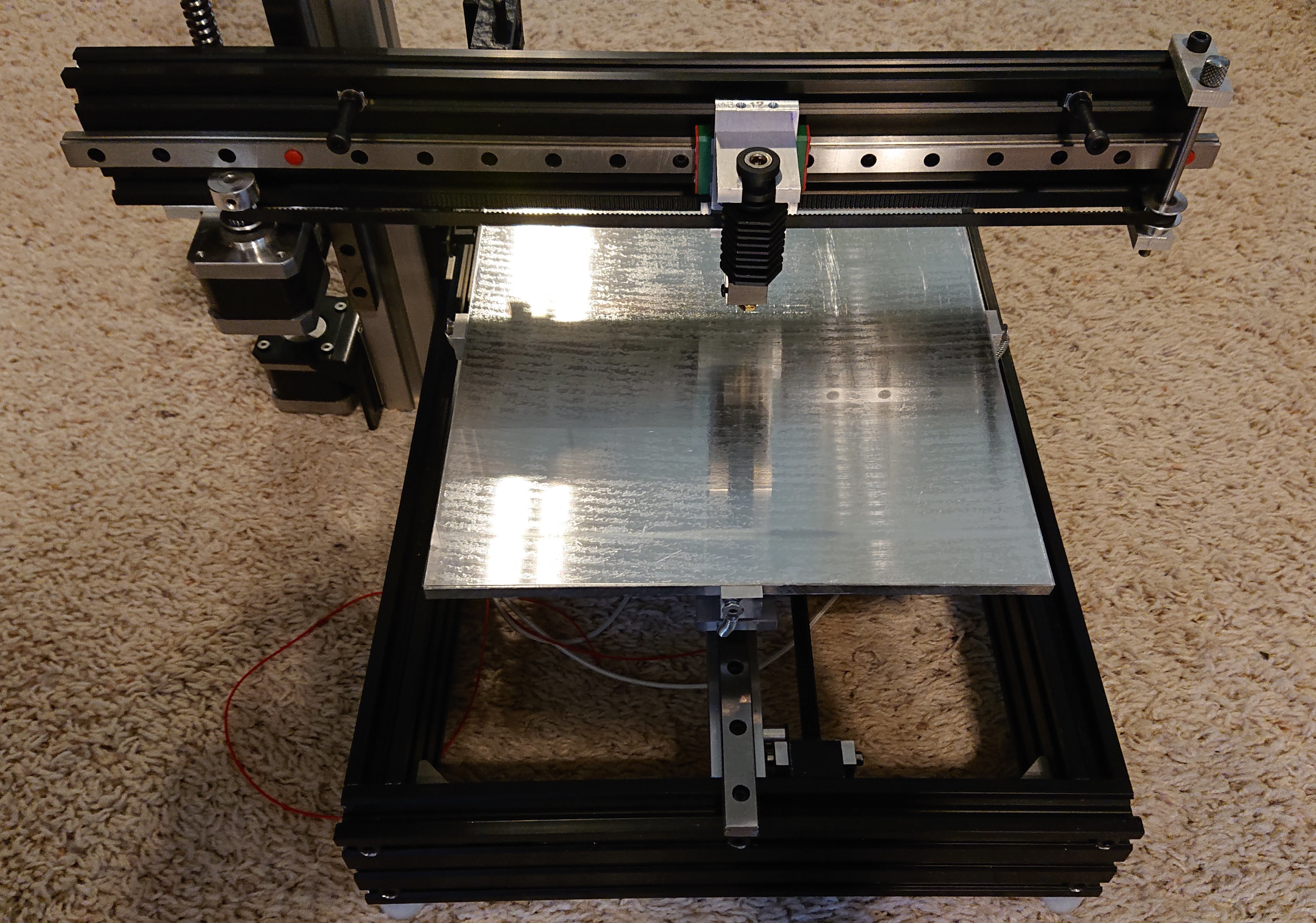
I installed the bed, and moved the tower even further back so that the current extruder configuration covers the full Y extent of the bed. (I will probably have to adjust that because I think I want a different extruder mount that I haven’t designed yet.) I have located how I will run the bed power and thermistor wires to not interfere with full travel. Here’s a video of me moving the bed back and forth by hand with the wires almost visible in the background…
I squared up to the frame, which I used as my square reference. I had to shim the cantilever arm with one thickness of soda can (about 0.2mm) at the inside end of the Z motion frame to get it within 0.1mm of square to the frame. I squared the tower against the frame with a try square. Then I did an initial bed leveling to the frame (I’ll adjust to the extruder later for final level). My idea to move the bed further up next time is a good one; it’s tricky to adjust the bed leveling screws as they are.
If I were designing it again, the bed support frame (“frog”) would extend back to or near the back of the bed, and the kinematic mount would be across most of the bed rather than balanced on the middle as Mark Rehorst does and tried on this design. I have the kinematic mount across the whole bed on my corexy, and I find that easier to work with. I may yet make this change as an upgrade later. It would make it easier to adjust the screws on the side because they could be moved where they weren’t inside the frame outline. (The end screw moves out over the front and is much easier to adjust.) I would also make the frog extend 5mm past the edge of the bed to match the kinematic mount features; right now the springs that connect the frog to the bed are not vertical because I cut the frog before I thought of the kinematic mounting blocks. Design-as-you-go strikes again!
I cut the old 300mmx300mm PEI sheet down to size, applied the 468MP tape to it, and applied it to the bed, all without air bubbles as far as I can tell. I’m not 100% certain that it’s actually PEI since it is clear, not yellow; I guess I’ll find out. Since they sold the 300mm square sheet as a 330mm square sheet, I wouldn’t be surprised by another lie.
@Eclsnowman suggested that I use the trinamic sensorless homing for X and Y since I have rigid end stops in X and Y, which means that wiring will be a little bit simplified.
It’s beginning to look like a printer!
1 Like
I know PEI (ultem) comes in different grades and types. So that might be the reason for the color difference.
1 Like
I did in fact move the tower further back. In fact, it’s almost all the way at the back corner now.
I decided to put an aluminum titan clone extruder from XCR3D on it and save the lighter bondtech to put into the corexy when I design a mount for it. (I haven’t figured out a way yet to fit the bondtech into my corexy frame though.) I am putting an XCR-BP6 24V 50W hotend directly into the extruder. I replaced an M3 set screw for locking the hot end in place with a proper M3 screw, which is substantially sturdier.
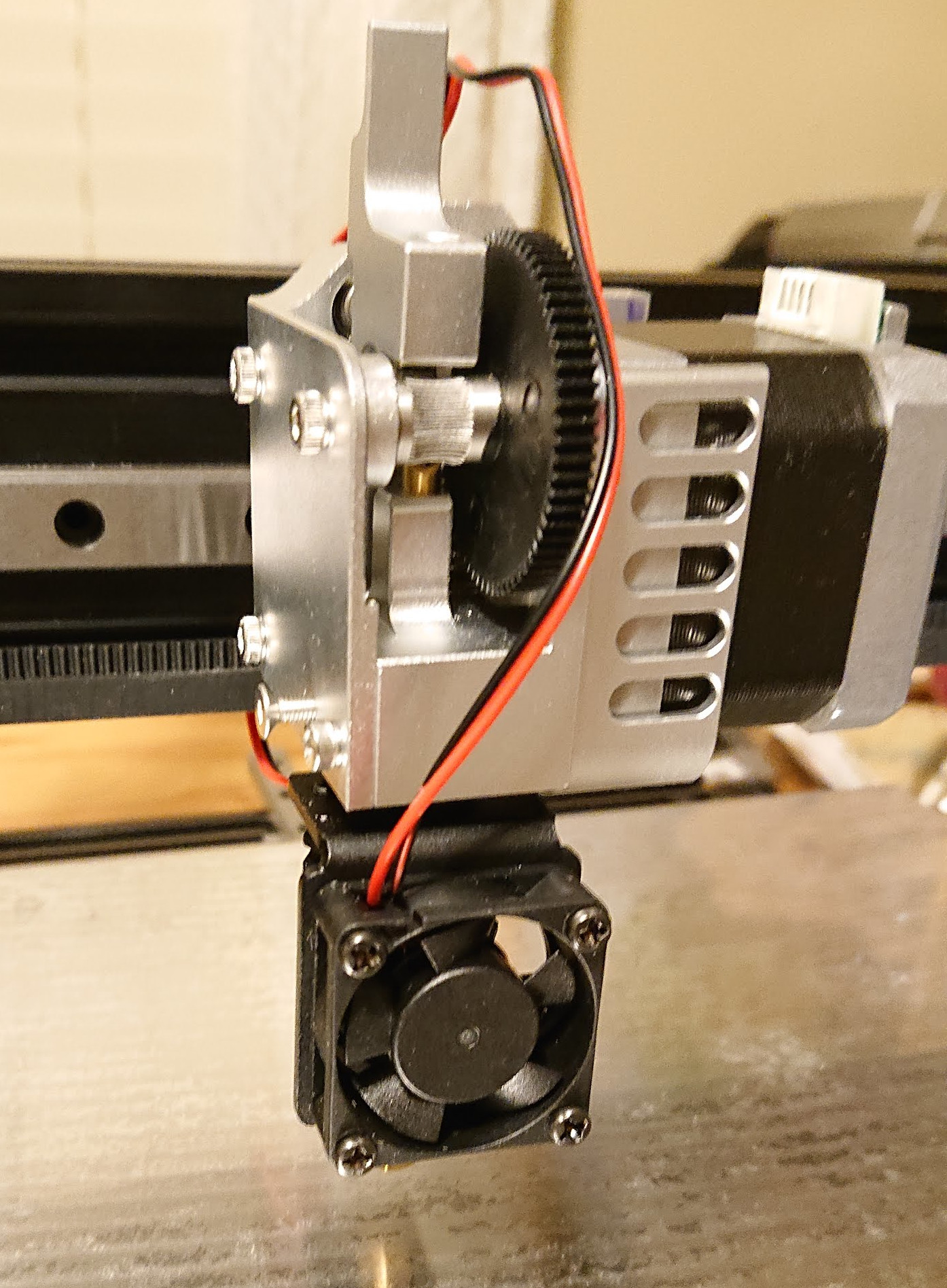
I had real trouble coming up with a workable way to mount that extruder without redesigning my X stage. I ended up having to turn part of it sideways and mount it with a blind screw that I tightened with a hex key that I shortened the short end a bit on my bench grinder. Here’s a side view that shows up little belt clearance I ended up with:
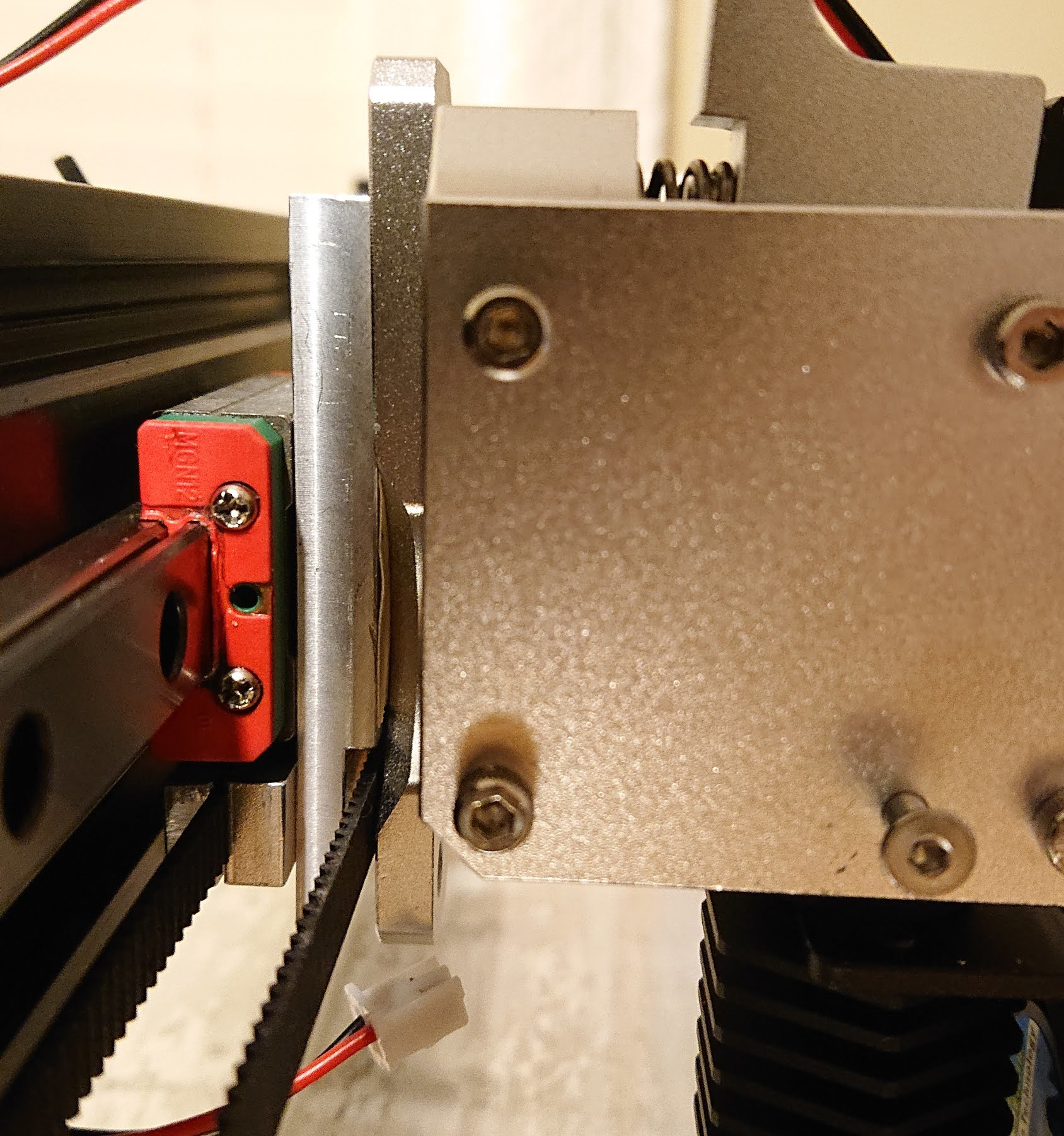
That’s a terrible hack. If I’d decided ahead of time what my plan was, I would have ended up with a very different design. This one I would have had some choice words for the idiot who designed the printer if I didn’t know very well who that idiot was. ![]()
All that’s really in the way of printing right now is wiring. I’ve misplaced two of my stepper motor cables and am trying to decide between just buying another few sets or making them from old ethernet cables I have around the house. I’m going to run this at 24V which gives me more flexibility in choosing wires.
- X stepper motor harness
- Extruder stepper motor harness
- Heat sink cooling fan wiring
- Print cooling fan wiring (I’ll won’t install the print cooling fan until I design a new duct; the one I put on the corexy isn’t good enough)
- AC wiring and SSR.
I’ll replace the heat sink cooling fan soon enough; the fans they ship with the hot ends are rubbish that die in hours. But the included fan will get me through first prints.
Finally, of course, I’ll have to build custom firmware. At least that part’s easy, especially because I’m using the same control board that I’m currently using for the corexy.
I feel like I must be missing something, but I can’t think what else needs to be done before first print. (Famous last words.)
2 Likes
“When you come to a fork in the road, take it.” I ordered some stepper motor cables, and then got impatient and made some myself. Note sure which I’ll end up keeping.
I’ve hooked up all the wires now.
I had a little trouble with sensorless homing because I’ve never done it before. I had to learn that I needed to jumper the DIAG pin from the stepper drivers to the respective stop pins:
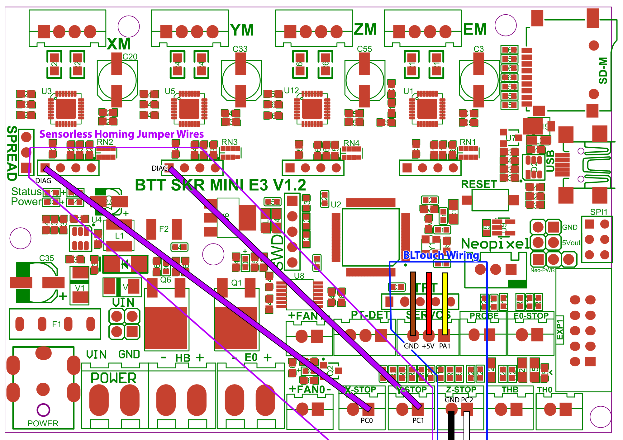
Then I had to find the right sensiitvity, on an arbitrary scale from 0 (insensitive) to 255 (very sensitive). The default, 8 (very low sensitivity) didn’t work at all. 100 was too sensitive and triggered from moving the axes. 45 worked ok for me on both X and Y, but 40 was too sensitive. It’s still a little jarring hearing it bang against the hard stops while homing, but I’ll get used to it. That or design and install more optical endstops!
For the optical Z stop, I picked +5V off the middle servo pin that I’m not using.
Time to button up the case!
It turns out that case is packed with wires. I can’t fit fans in there with wires running through it, but due to the same mess of wires that makes the fans not fit, I’m a little worried about airflow; I may have to screw a fan onto the bottom of the case.
- The first time I screwed on the cover, the tray had come out of its slot; this is hard to avoid, and if I redesign the case I’ll make a boss to screw the tray into place from the back (printer) side to hold it in place, as well as making a bit more room.
- The second time, the spade connectors pulled off the power switch; I added a strain relief to the power cable.
- The third time, the bed thermistor wire came loose.
- The fourth time, everything stayed connected, it seems, including the extruder stepper connection that I apparently forgot to check and was backwards. I just rebuilt the firmware to invert extruder direction rather than taking the case apart again.
I’ve worked out that I can use tape to hold the tray in place until the cover is screwed most of the way on, then pull the tape out and screw it the rest of the way together.
First plastic printing now!
3 Likes
I’m excited to see how the first print turned out.
1 Like
I managed to accidentally leave 200 steps/mm instead of the correct 800 in settings by not saving settings after restoring default, so it was trying to print layers with 0.3 mm worth of plastic but making them only 0.075 mm tall. You can imagine how well that worked. I am very glad I didn’t look at the beautiful-looking first layer, declare victory, and go to bed!
That may also have been responsible for the loud bang on sensorless homing; I was perhaps using too low a sensitivity value for the same reason. Now it’s just a moderate tap. (Actually, not sure; sometimes it’s a moderate tap and sometimes it has the classic “grinding against the end” lost step noise for a couple steps, even with the fixed settings. Maybe that means I should adjust it more?) I’ve really solved this by lowering the sensorless homing current to 200mA, which seems to work fine and also results in just a mild tap each time so far.
The PEI (if that is what it really is) sticks too well. I’m having trouble removing prints. Probably I’m printing at too high a temperature, using bed temperatures that might be appropriate for printing on glass. I’ll try turning that down. Looks like others have seen this; maybe I should try windex instead or in addition.
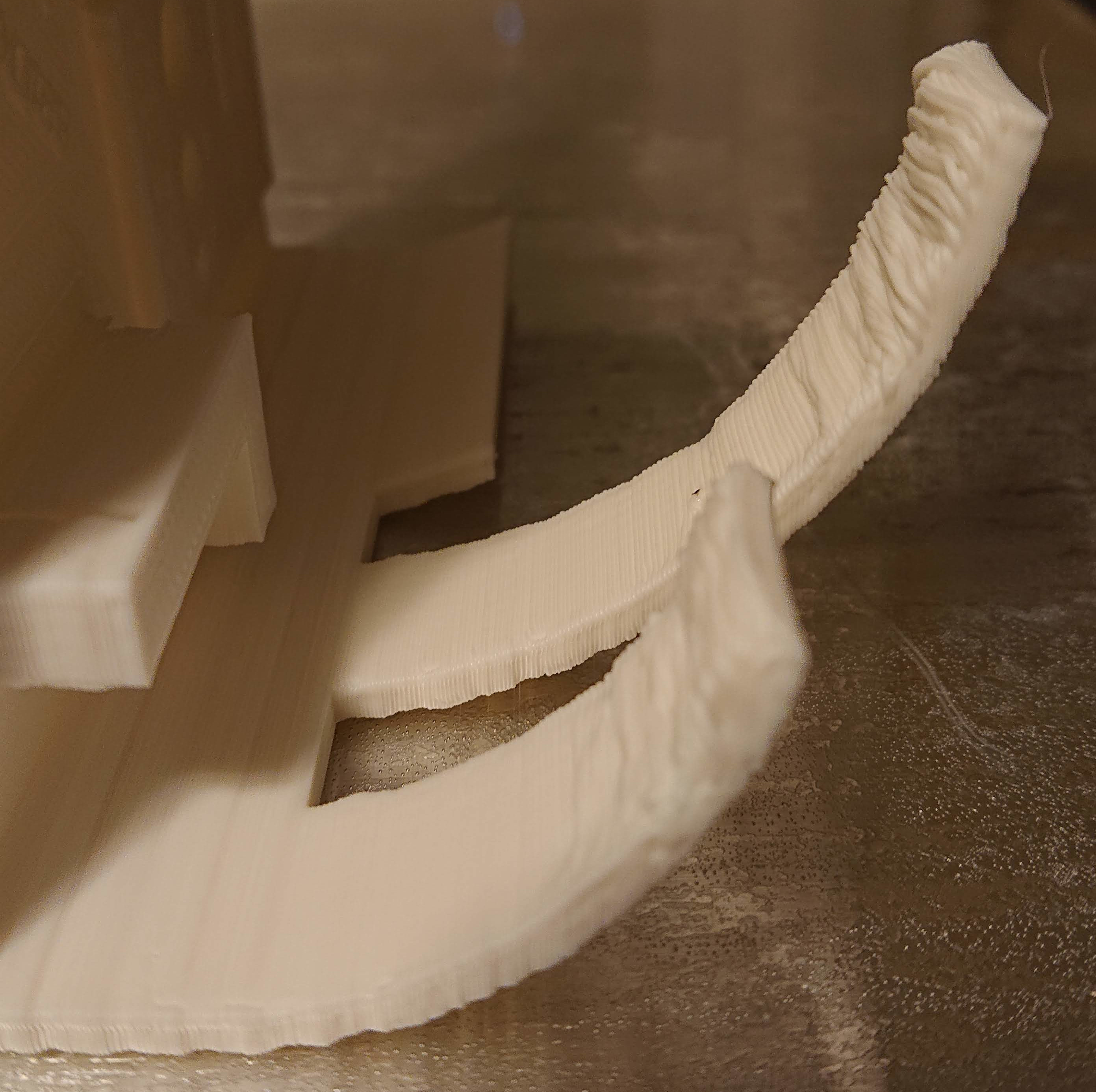
I changed my mind and am printing my 40mm fan adapter and shroud as my first upgrade before I design a new cooling fan duct; it needs it. …It turns out that the print cooling fan has a bridge of over 30mm and printing it hot for PETG (260⁰C) without a cooling fan it droops a little. (I re-formed it a little with my fingers after printing while it was still soft, so it should work.) But to print the cooling fan duct right, I need a cooling fan duct. 
Here’s the first working print! The printer needs more work, but it’s in better shape than the old gantry printer it replaces.
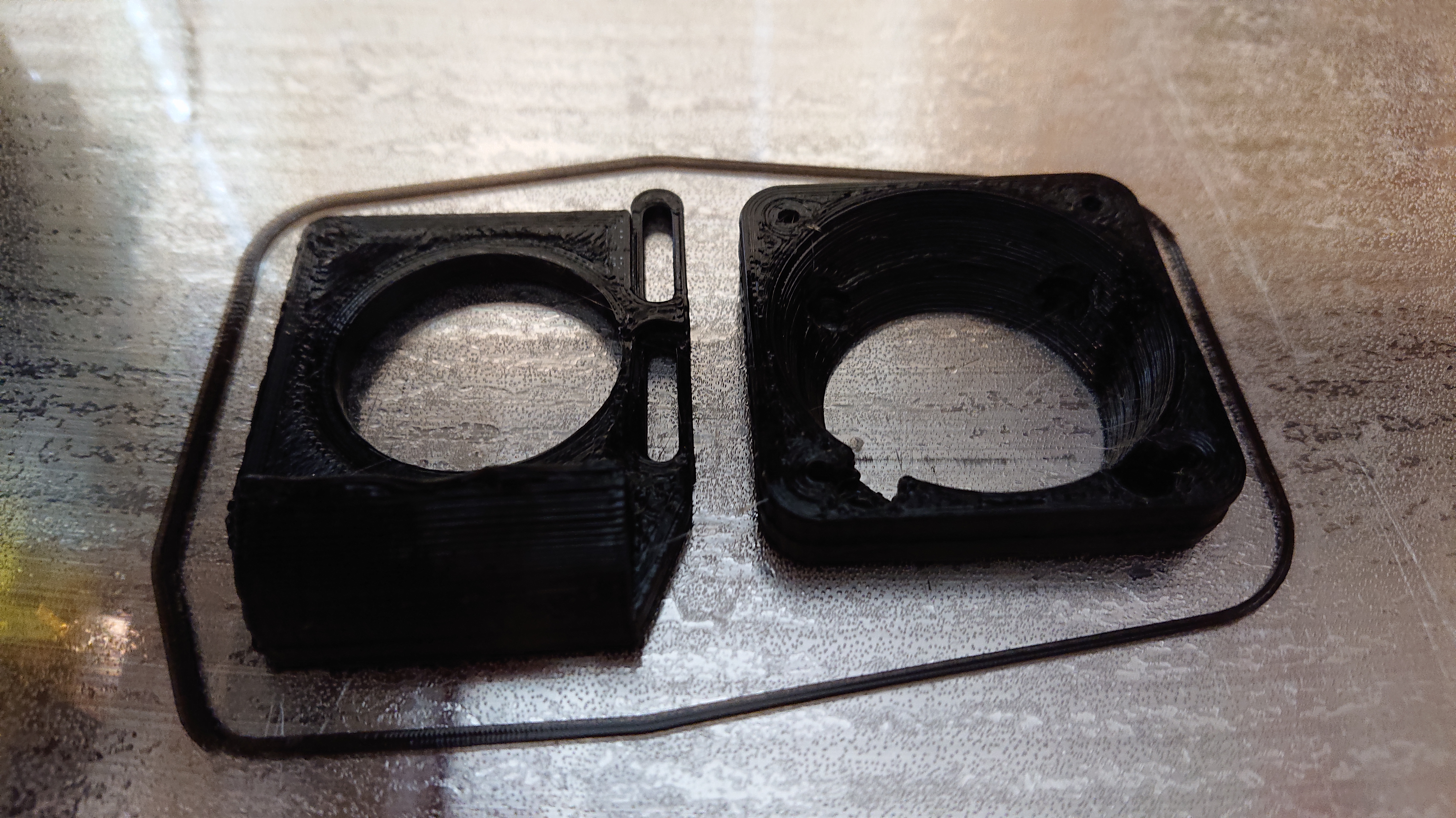
You can see that I still need to do a pid tune — after I put the fan shroud and cooling duct on and wrap the hot end in kapton tape.
Here it is, mounted on the printer:
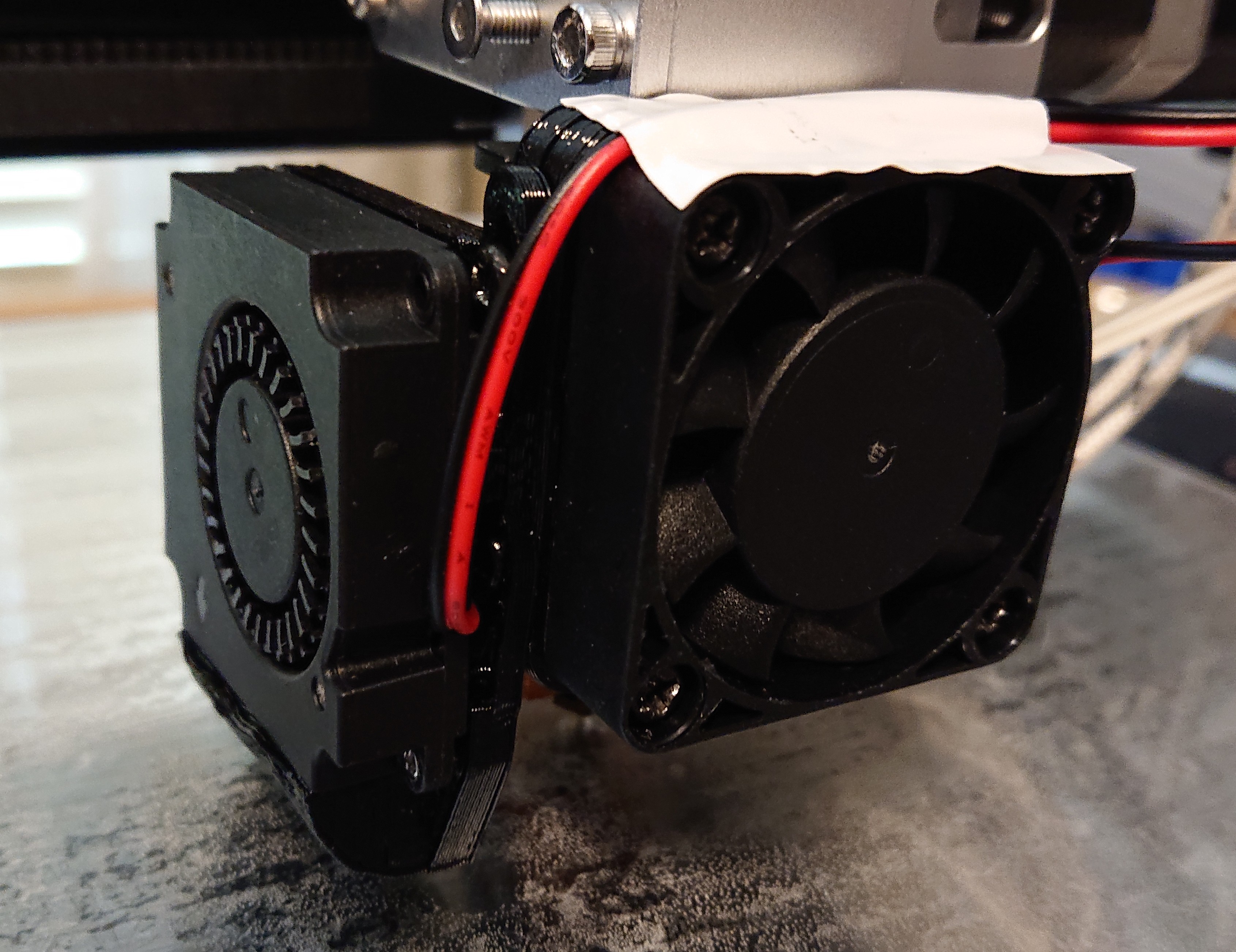
I wrapped the hot end heater block in four layers of kapton tape and used more kapton tape to make a shroud to keep air from the heat sink cooling fan away from the heater block.
The hack for mounting the extruder isn’t quite steady enough. I think that instead of using the mounting plate that came with the extruder, I’ll make my own. I had already put a set of M3 holes 12mm apart on the top of that piece mounted on the block, and I have an idea for a slightly less hacky design that utilizes those holes for a steadier mount.
I’ve been measuring the temperature of the bed. I have a 200mm x 200mm heater centered under my 224mm x 274mm bed, which isn’t obviously optimal. Once the bed reaches steady state, though, there’s only 2⁰C difference between the center and the edge. That’s better than I expected. Given that, especially for a printer that is rarely used to print footprints substantially exceeding 200x200mm, I think I’ll count this as a win.
I haven’t figured out where to put drag chain yet to make the wires look neater. Right now, I have some of them (bed heater/thermistor, all wires to the extruder) wrapped up, but that’s it; I have rather a tangle of wires at the side, which makes the case look less beautiful. I’m so happy about printing, though, that I’m not in a rush to fix what ain’t broke. For now, I just used some cable ties to hold wires more neatly bundled together. The ugliest thing is the X stepper cable hanging loose off to the left of the printer.
Print volume is 224 X 274 Y 290 Z — bigger than makes much sense for a bed-flinger printer.
2 Likes
I got so excited about printing, I forgot to PID tune. The hot end and extruder are the same as the corexy and so its settings are probably fine, but the bed has more power per area and so the values it inherited from the corexy are most likely not optimal.
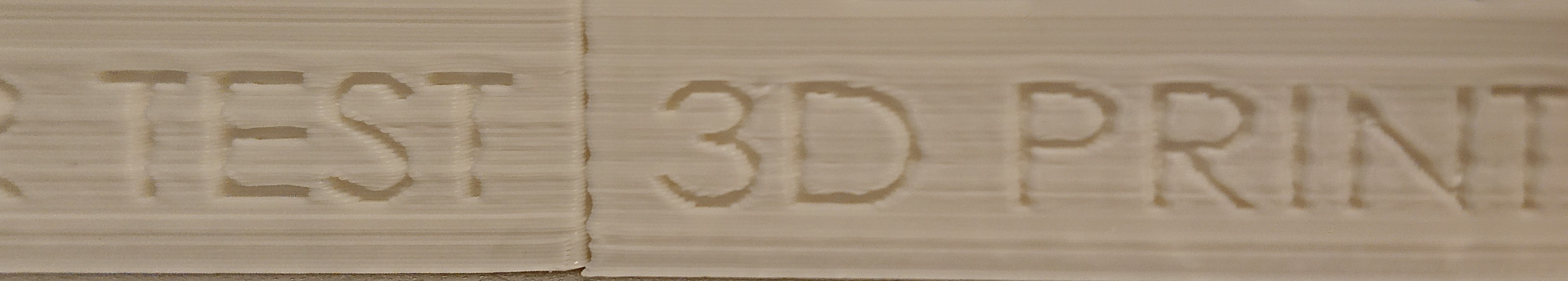
I woke up this morning to the results of a 2h50m overnight print of an all in one 3d printer test. I’m hoping that wrong PID parameters are what is responsible for these banding artifacts:
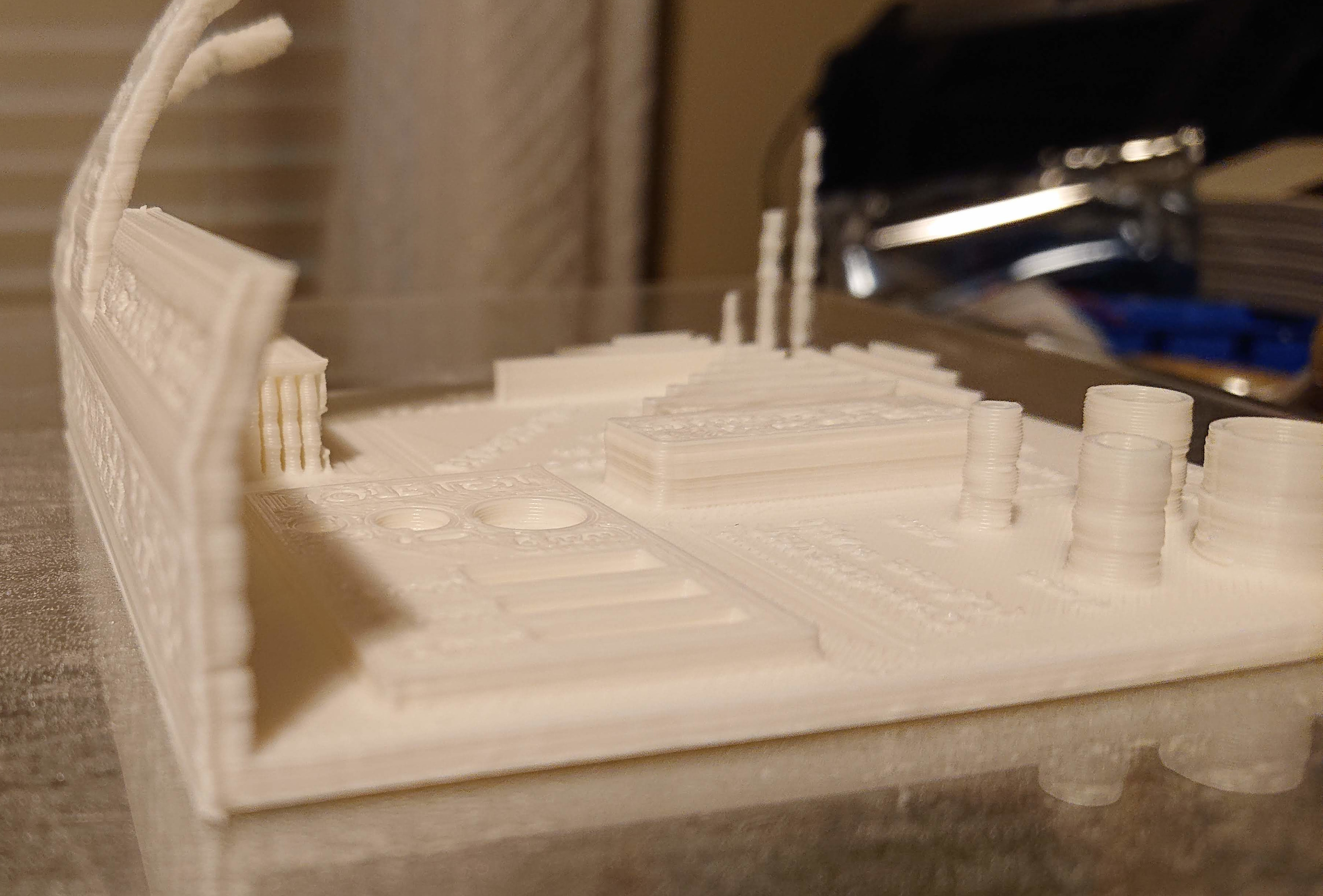
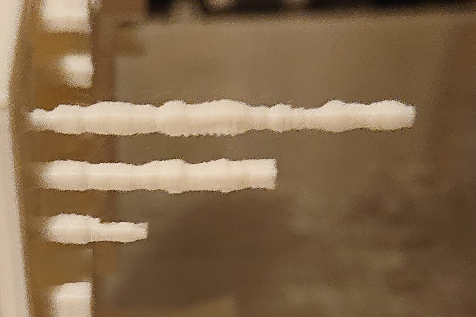
Bridging looks perfect to 25mm. I should increase at least bridging speed.
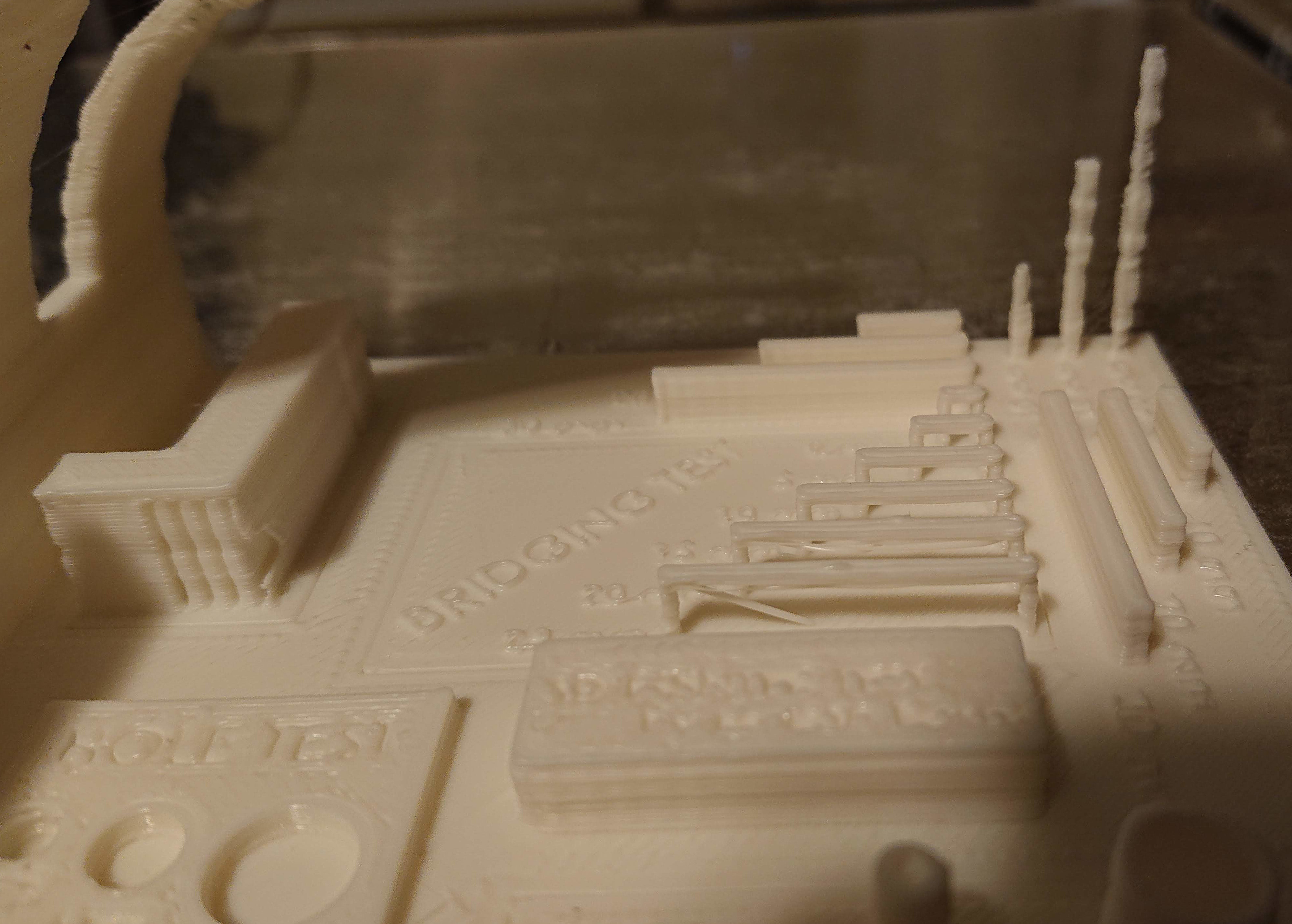
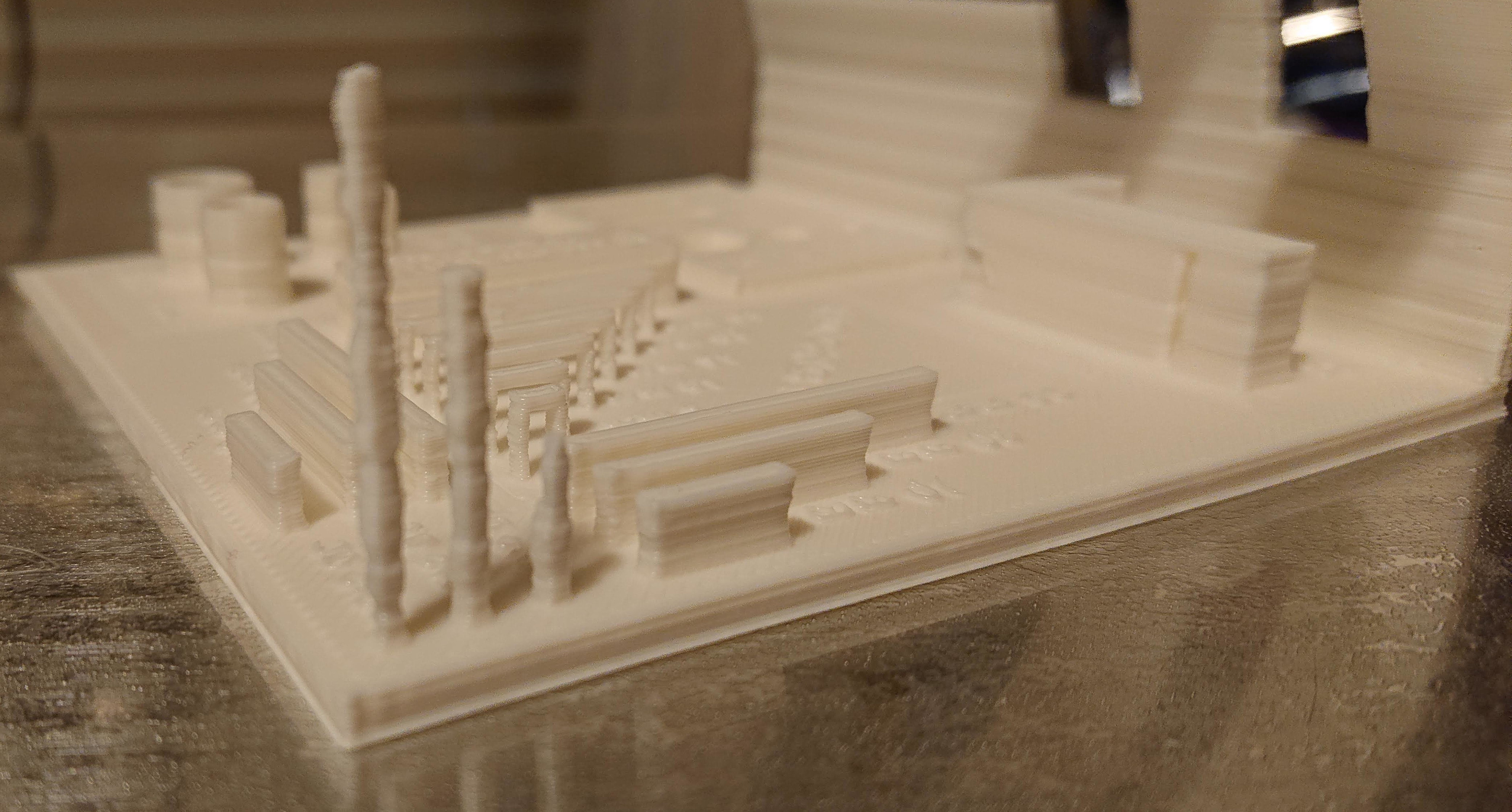
Set on the side to show the overhang tests more clearly:
The fact that the banding looks different on the 10/20/30 mm towers from the side gives me hope that this is a thermal problem, not a mechanical problem:
I think I can probably speed up a lot. This is at a very conservative 60mm/s max print speed. At least, it’s conservative for the hotend, which is 24V 50W.
But I’ll change one thing at a time. PID tune and the same gcode first; speed up later…
That’s a substantial change. So, reason to hope that the print I’ve just started will be higher quality. I’ll see the results in about 3 hours!
diff --git a/Marlin/Configuration.h b/Marlin/Configuration.h
index 337949abc..3ba7376bc 100644
--- a/Marlin/Configuration.h
+++ b/Marlin/Configuration.h
@@ -489,9 +489,9 @@
   //#define DEFAULT_Ki 1.54
   //#define DEFAULT_Kd 76.55
   // M303 E0 C8 S250
-  #define DEFAULT_Kp 7.31
-  #define DEFAULT_Ki 0.31
-  #define DEFAULT_Kd 43.65
+  #define DEFAULT_Kp 13.37
+  #define DEFAULT_Ki 0.83
+  #define DEFAULT_Kd 54.14


 #endif // PIDTEMP
@@ -542,10 +542,10 @@
   //#define DEFAULT_bedKd 1675.16

   // FIND YOUR OWN: "M303 E-1 C8 S90" to run autotune on the bed at 90 degreesC for 8 cycles.
-  // This was: M303 E-1 C8 S70
-  #define DEFAULT_bedKp 41.36
-  #define DEFAULT_bedKi 7.48
-  #define DEFAULT_bedKd 152.51
+  // This was: M303 E-1 C8 S90
+  #define DEFAULT_bedKp 39.67
+  #define DEFAULT_bedKi 7.28
+  #define DEFAULT_bedKd 144.18

 #endif // PIDTEMPBED
1 Like
Which type of z-spindle coupler do you use? I had such a behavior (but every layer equal) on my Ordbot Hardon when I used the cheap spiral aluminium cupplers. It was gone after I replaced them with the better (uncompressable) ones.
While the print hasn’t yet finished, I can tell that the problem isn’t resolved by PID tuning. From the periodicity, I was afraid it might not resolve it.
Good call! It is in fact the cheap aluminum spiral kind; one of the few parts I used from the old gantry printer in order to stick to my original “leftovers” design constraint. I think it theoretically shouldn’t matter whether they are compressible, because the motor doesn’t support the Z axis; the Z axis rests on a bearing, with the motor floating below it. But I wouldn’t be surprised if slop in the bearing is being played by the coupling; the motor isn’t perfectly aligned due to some design mistakes I made earlier (not accounting for the difference in thickness between making my own motor mount from aluminum angle vs. a thinner purchased steel motor mount).
I can and should play with shims a bit more to improve the alignment. I could also try pulling the motor down a bit, opening up the spirals on the coupling, so that it’s always loading the Z stage reference bearing in the same direction.
I’ve ordered a spider (lovejoy style) coupling, but it might be better to put the spiral aluminum coupling in tension, better aligned, in order to preload the Z reference bearing to remove backlash.
…I did shim for better alignment. Now the motor shaft slides into the coupling smoothly without obviously displacing it at all. But it turns out that the motor obscures the screws for the motor mount, so I can’t easily preload the bearing by stretching the coupler. I haven’t gotten enough printed to tell whether it’s better or worse, but at least the problem hasn’t gone away entirely.
It’s mildly better, but also I can still see mis-alignment of the coupler from another angle. First version on the left, second on the right:
I started taking apart the Z axis to add more shims. I removed the stepper motor. Then as I loosened the screws holding the ball nut to the Z lift plate, the whole Z stage self-drove down.
Then I was able to see that I had yet another misalignment problem I hadn’t seen before, also due to trying a “shortcut” of not building my own mounts and altering the design to fit. I hope this time I get it straight.
1 Like
With the cheap spring couplers I find if you preload them a bit it makes a pretty big difference. So tighten it onto the motor shaft and then pull it up the 8 mm shaft and then tighten it down so it pulls itself down to the motor shaft. You only really need the spring miss alignment for x and Y but having it pre-loaded on z means that the springiness of the coupler shouldn’t affect the hops and fast z moves.
Also double-check your currents on the motors. When I recently rebuilt the adoptabot I had a pretty substantial difference in print quality just by changing motor current and nothing else. Left to right in the image below is upping my x,y, and z motor current.
I found quite the litany of Z stage problems so far. So many, in fact, that it’s possible that I am not remembering them all. ![]()
- My ball nut was not square to the Z linear rail it must align with; this alone prevented it from running free, and I could feel clicking from the balls entering the race. A couple small shims seem to have resolved that problem.
- My bearing seat wasn’t perfectly aligned in Y with my ball nut, by over 1mm, and it couldn’t be aligned with the NEMA17 motor mount I had re-purposed to hold it. I had to mill out a mounting slot wider, and stack a wider washer on the mounting screws, to move the mount far enough to make the bearing seat align in Y.
- My stepper motor, for the same reason as the bearing seat and by the same amount, needed its motor mount slot milled out to align with the ball screw.
- I had the motor shaft and ball screw shafts nearly touching inside the coupling, making the flex in the coupling almost completely unusable. I marked both shafts with sharpie before re-assembling so that I would not repeat that mistake.
Today I (Re)Learned
The tight tolerances of even a relatively low-quality ball screw system are a very poor match for fly-by-the-seat-of-your-pants re-engineering. Almost everything I ran into is directly or indirectly attributable to swapping out making my own mounts for mounts that I purchased in an expectation of saving time.
I would probably have seen none, or nearly none, of these Z artifacts had I just opted for single-start T8*2 lead screw as I have done in other printers. I even had some that I had previously installed as an upgrade in the junk gantry printer that I tore down at the beginning of this project. $20 could get me a new 400mm T8x2 plus an anti-backlash nut, ordered on amazon, and arriving in a few days.
If my rebuild of the Z stage doesn’t resolve, or mostly resolve, these artifacts, I may do just that. The only reason I would hesitate is that I would have to work out what to do about fitting it to the Z lift plate designed for the ball screw nut.
If I do get this printer working well enough to consider creating a new design that others could build, I’ll be making changes from lessons learned, and I won’t inflict the ball screw on others in such a design.
The “design” of my Z stage makes it almost impossible to effectively preload Z. I managed to add some pre-load on reassembly, but only by leaving the motor mount loose enough to push down the tower, away from the Z bearing, after I screwed the motor into the mount. It’s not clear to me that it will maintain that preload.
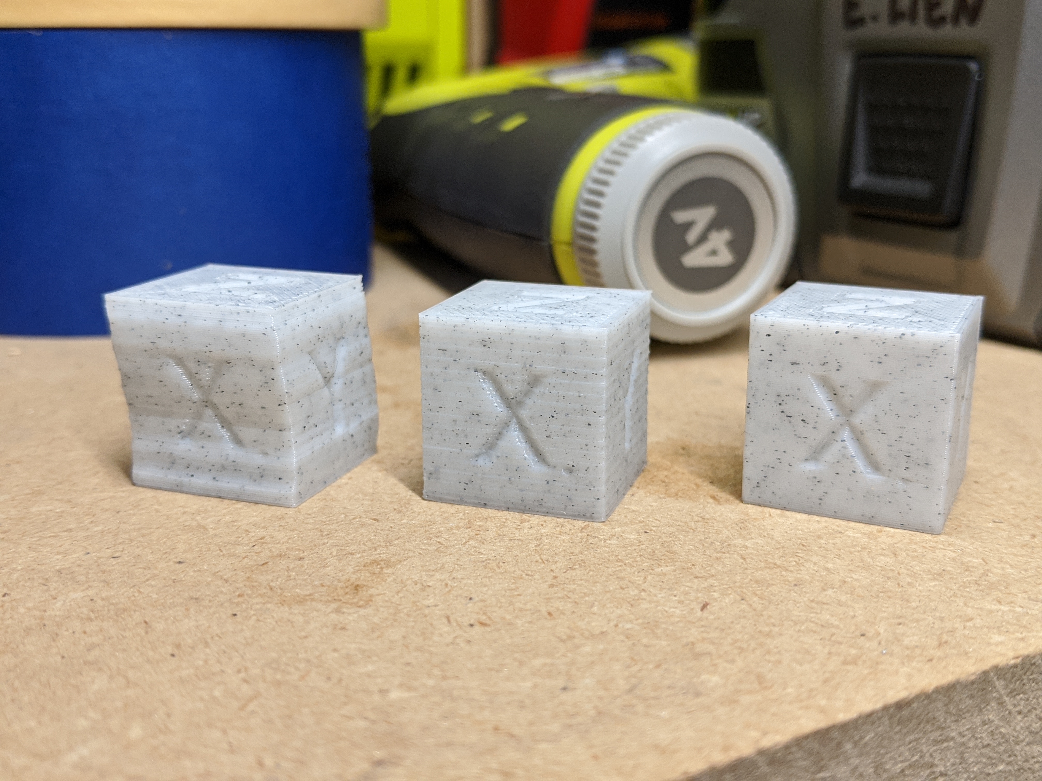
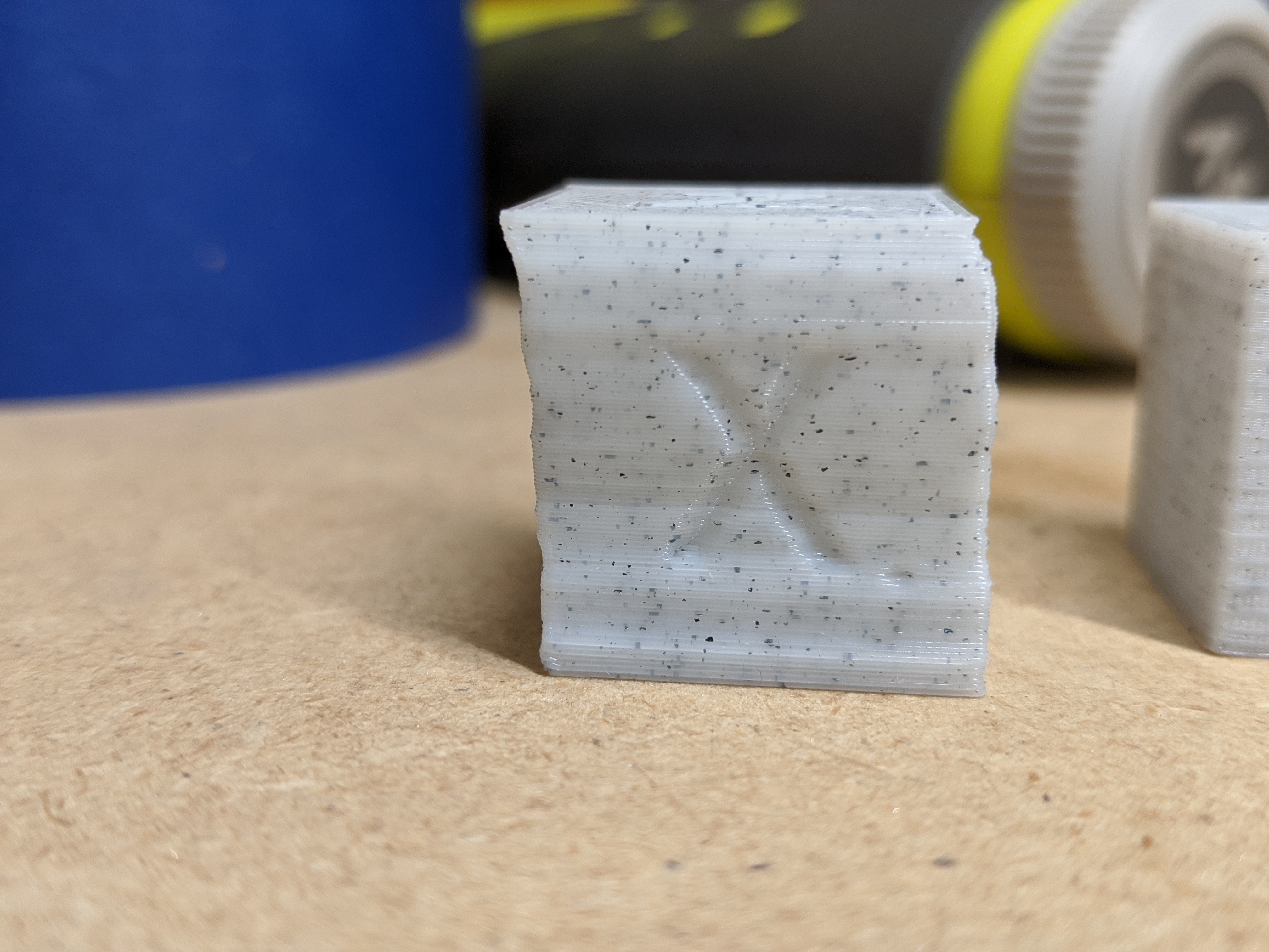
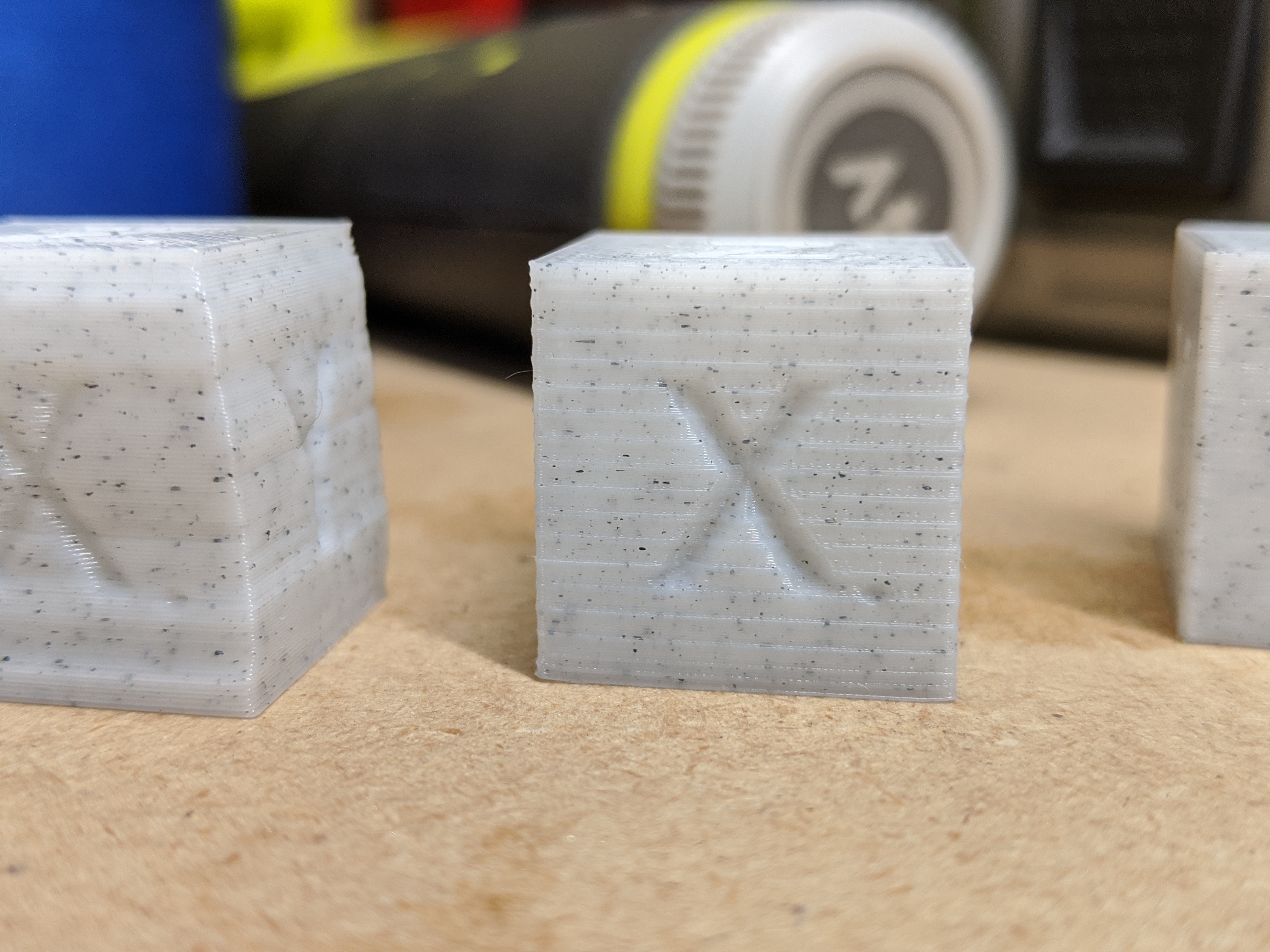
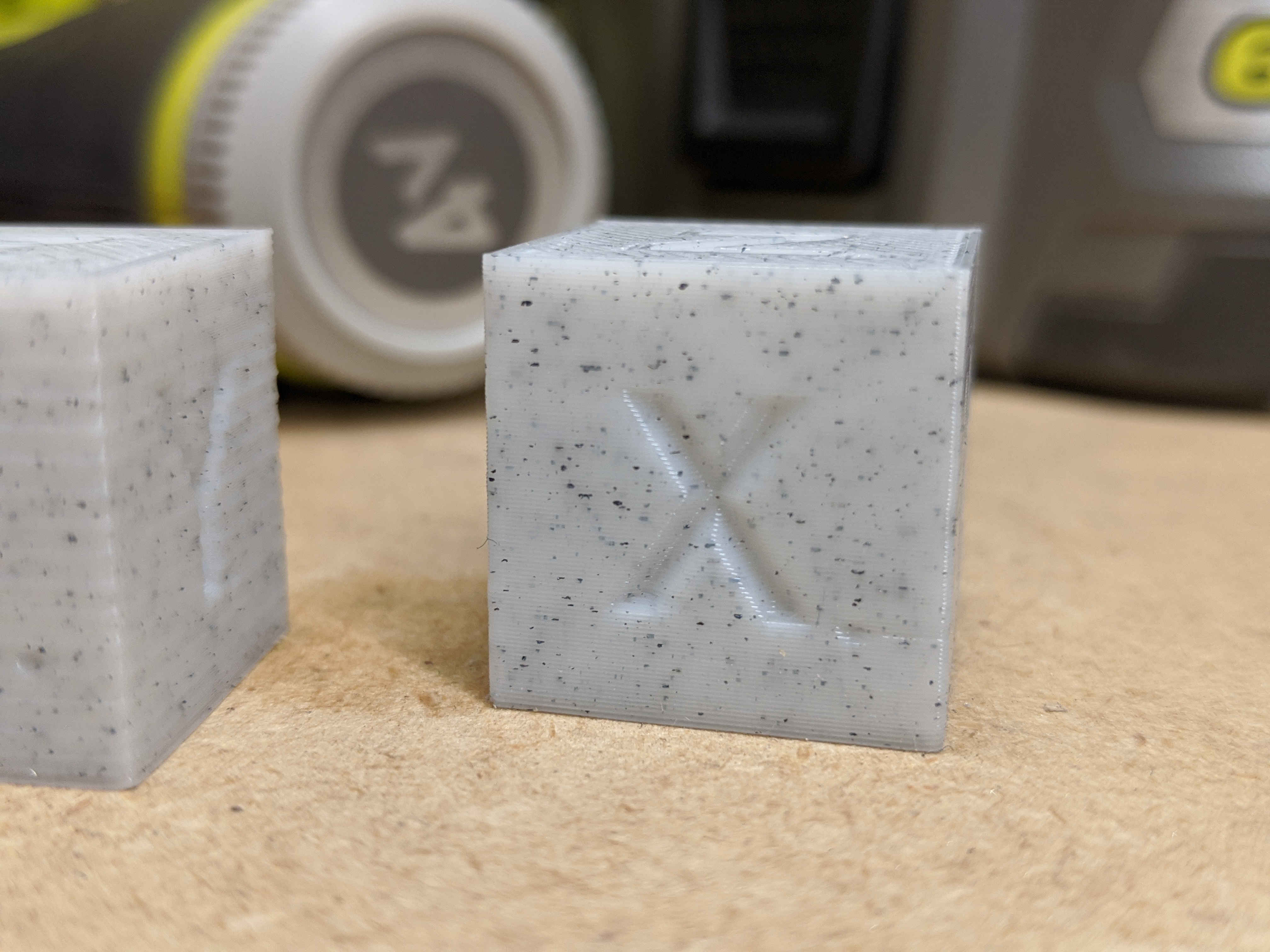
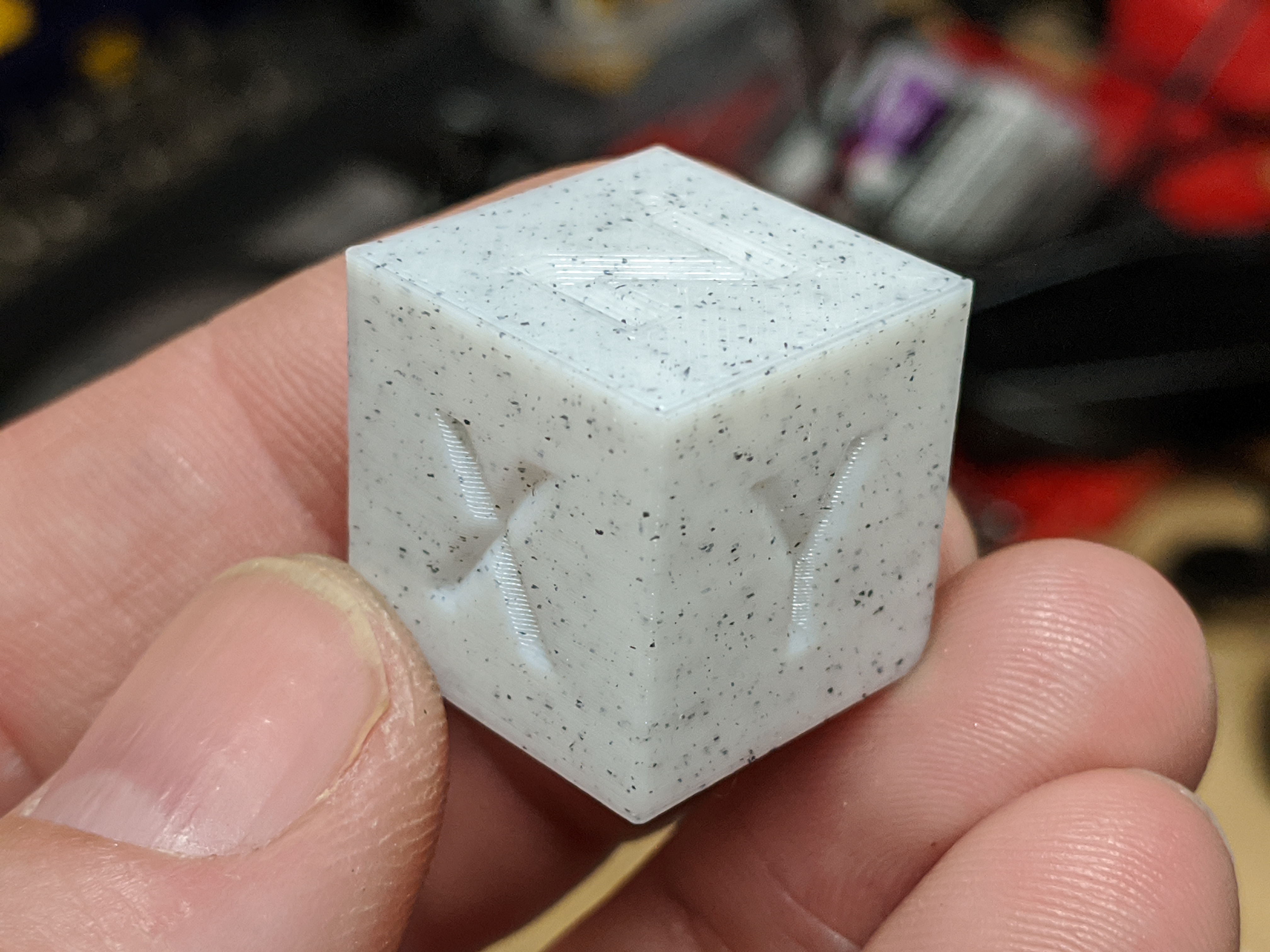
Those calibration cubes tell a story!
The motors I got didn’t come with a spec. I was running them at about 1A in the donor printer (analog potentiometer). I’m running them at 800mA in the new printer and could probably run them lower. I’m sensorless homing at 200mA and that might be overkill honestly.
The fact that Y throws around the relatively heavy bed with no problem at 800mA means that X should require substantially less, and Z really doesn’t get much of a workout.
…
This is much better. It’s still printing, but the first 12mm or so are tremendously better. I’ll do more tuning, but at this point I don’t think I’ll even bother swapping in the lovejoy-style couplings when they arrive.
Fixing the Z stage took the time I had expected to use to make a new mount for the extruder, though, so I’m still using the hack.
I haven’t yet decided what to do for mounting the power supply on the other side. I’ll at least want to print a cover for the power so I’m not exposing 120V. But for mounting it to the frame I haven’t decided yet.
…
After Z axis fixes on the left, compared to previous print on the right:
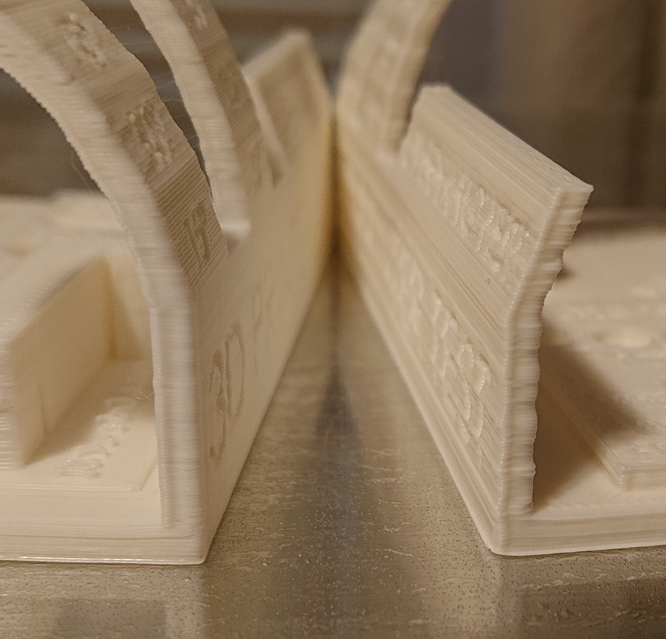
Still need to tune acceleration at least, but the worst problem is resolved.
2 Likes
The amazon description said that it wasn’t thermostatically controlled, but it clearly is, since it cycles on and off while the printer runs.
To decide whether it might ever be worth doing this, or merely redundant, I searched for other cantilever designs. I was surprised at how few there were. None of the few examples I found used a rectangular frame; they all used some form of T or F frame, and were primarily intended to use minimal material. I believe all the examples I found used a smaller bed than mine.
In my design, the rectangular base provides both stiffness and weight counterbalancing the tower, which is itself cantilevered off the side of the frame. The other designs support the tower from both sides, so they don’t need a cantilever counterbalance. When this started out as a gantry design, the rectangular frame made lots of sense. Then when I switched to cantilever, it made sense to keep it in case I needed a small stabilizing tower at the other side of the arm. I still don’t know whether I’ll eventually want to add that stabilizing tower, since I’m still experimenting with quality.
My general design is based on quite a few custom milled aluminum parts, all of which I milled using HNC (Human Numerical Control, manual mill with DRO). It really requires access to a mill, or at least to a good stiff CNC router. Feels to me like the intersection of interest and capability might be low for this machine. I’d think that most people with sufficient interest to build something from scratch including milling custom parts are probably going to go corexy or hbot these days. Hard to spend the time to model it without a reasonable expectation that someone would someday find it useful. Seems like there are so many more objectively better designs out there that started from more meaningful design constraints than “my project leftovers!”
I’d think that the first question would be “How much would it cost to make?” and that I can’t answer without a sense of what someone would charge for a set of aluminum plates. Looking at the various sets of plates Blue Ox (chrisclub1) sells on ebay (e.g. for the OX) my set would be less aluminum but more parts, more complexity, and more tool changes, so $150 feels like it would be on the low side, probably more like $200, not counting the bed. Probably more if some parts need to be cut from something other than ¼" sheet. Then for all the other parts, if I had needed to buy them new, and substituting less expensive and more appropriate T8*2 lead screw for the ball screw, it’s probably over $600 more of BOM. So a finger-in-the-wind total estimate would be a minimum $800 BOM for someone without a machine shop handy, easily $1K by opting for high-quality stuff. My cost to upgrade from what I had already lying around from a few years of other random experiments was under $100 (not counting a few items I refreshed stock on after depleting for this project), which was rather more manageable.
Would anyone spend $800 plus days of time building this when you could, say, get a far more capable FT-6 for substantially less?
1 Like
I guess it depends upon the goal of the builder. I always try and put my stuff out there only because maybe it’ll inspire someone, or they can take the parts that I took the time to model and use them in their assemblies. But you’re right the amount of time it would take to make this a fully documented project probably wouldn’t yield the results you want in the days of ender 3’s. Maybe 5 or 6 years ago, but today the majority of people out there use the printer as a tool not a hobby.
For me a lot of the time it was just the calming aspect of sitting at the CAD station and doing real detailed work, it’s amazing how 5-6 hours can disappear in the blink of an eye when you’re working out the details and making sure everything’s perfectly aligned. But I’m weird like that, I enjoy the process
Perhaps just take the models of the things that you’re happy with and make any modifications you need to for the cad you’ve already done and put those out there as kind of a free-for-all, grab it if you need it.
2 Likes