Be gentle with me I’m new to all this…Complete Newbee…
I’m building a worktop mounted linear rail CNC this wood router. I bought some stepper on line Nema 23 motors X4 for X,YY and Z Axis. I planned to run them off a Makerbase 32bit DLC32 with a small screen and 4 DM556 drivers. So far so good, I hope.
Unfortunately I have met a few problems.
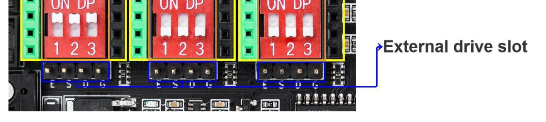
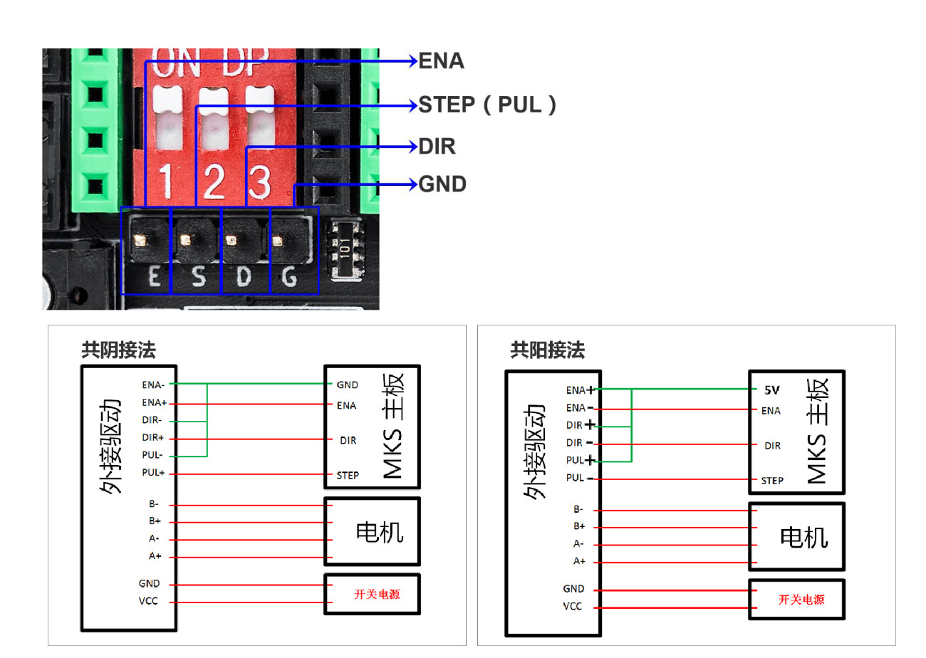
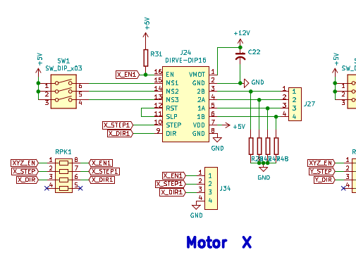
I have connected the drivers form the pins behind where the plug-in drivers would go, these are marked E,S,D,G. and have connected them to E=ENA+, S=Pul+, D=Dir+ and G=ENA-, S-, and PUL- linked together. Hope that makes sense.
The power side of the driver has a 36V power supply and the motors are connected (I have checked the motor winding continuity with a Multi Meter)A+to A- etc.
The DLC32 board has a 12v Power supply.
Trouble is when I ask the touch screen to move a motor I can hear the driver doing something but the motor sits there completely disinterested.
I do however, get a constant red LED on the driver but when I ask the Y axis to move (via small screen) the red light goes off and the driver makes a quiet noise like it was trying to do something. But still no movement on the motor. I checked for voltage on the motor winding during this process, I was reading a small voltage(2.4v) on coil A but nothing on coil B, presuming it was ‘A windings turn’ ??.
I have swapped motors and drivers. Have I got the DLC32 connected incorrectly ?
Any info or ideas would be great, as I said at the start, CNC Newbee…Many thanks in advance.
Check the voltage on those pins; the DLC32 I think is 3.3V not 5V, and it looks like your drivers might want at least 4V.
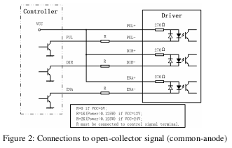
Maybe the board is set up for “open drain”? If so, you would connect 5v to ENA+, DIR+, and PUL+, and then connect ENA-, DIR-, and PUL- to the E, D, and S pins on the board.
Thankyou for the reply. I shall try that in the morning. I know there is a 5V pin at the Probe connection, or should I supply 5v from off board (power supply). I can’t see another 5V, unless I’ve missed it.
The one on the left is what I think you have done, but will I suspect provide only 3.3V which might not be enough to drive the opto-isolators in your external stepper drivers.
The one on the right is what I’m suggesting, but I don’t see yet how to configure it i the firmware.
That sounds like @Peteb’s wiring is intended to work. @jkwilborn do you see any evidence of open drain configuration being even supported? Maybe the wiring manual is wrong to suggest it?
I’ve had bad wiring result in something that looked like that, but it seems unlikely to be the same on all four axes.
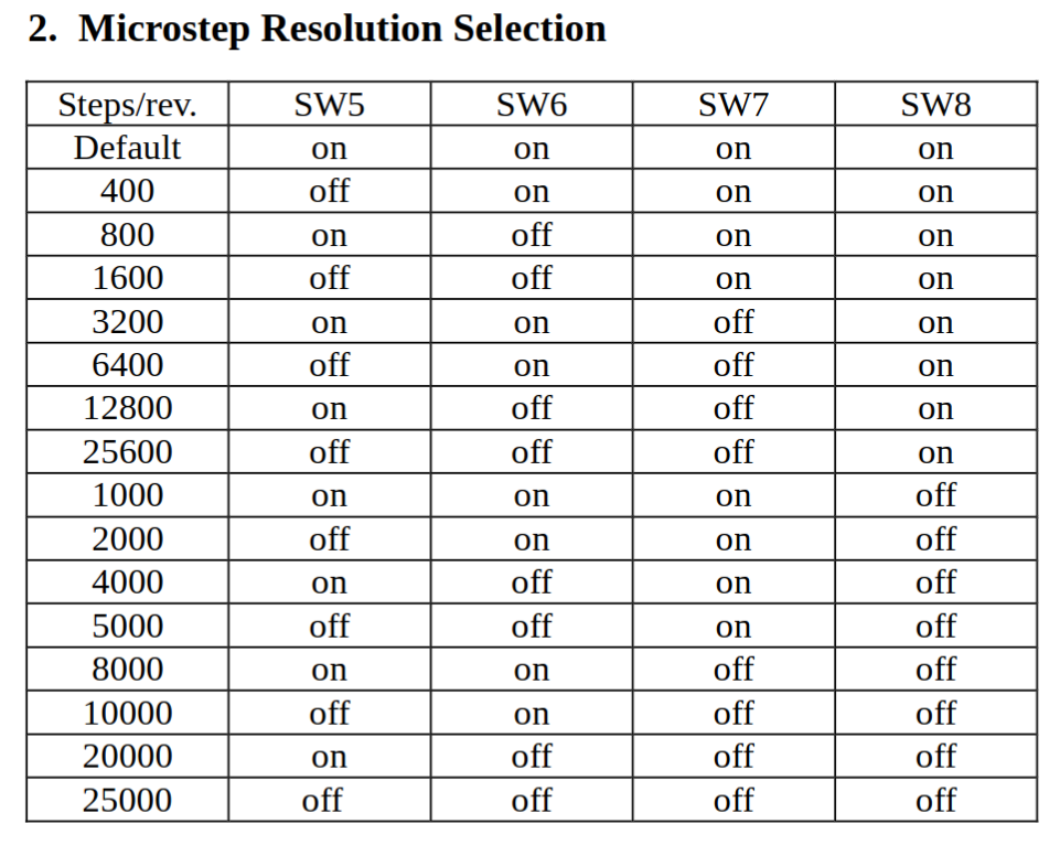
@Peteb how are the DM556s configured? Microstepping and current limits?
Hi Michael, I’ve set the amps to match the motors, was going to limit them slightly when working. and have set the steps to 800.
I used your advice from earlier and put 5v on ENA+ etc however the only 5v supply I have at hand is a ac/dc buck converter to 5v with the minus connected to ground on the board.
I also wondering if my 12v supply is adaquate as its only supplying 80ma to the board, I think the 12 supply is only capable of supplying 1A
.
Anyway the upshot is that the driver definitely sounds like its trying to do stuff (Louder) and it sounds like the motor wants to turn, (quiet clunking sound), the red light on the driver only come on when it is asked to do something by the small screen controller.Still no proper motion which is making me wonder if its the current supply or lack of it??
I don’t know that it will work on this board. It’s just one possible configuration for some systems. The makerbase manual is not clear as to which configuration works. You shouldn’t need a separate 5V supply in any case. The board has 5V on all the probe connections. But if it’s not set up for open drain then this will not help.
That’s why I was suggesting measuring the voltage on those pins, like the E pin (enable).
Then @jkwilborn found the schematic that suggests that 5V should be there, which means, as far as I can tell, that the “open drain” configuration would be wrong for this board. (The manual isn’t particularly helpful here.)
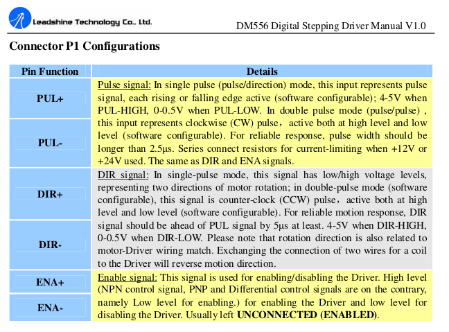
What is the microstepping configuration? See the manual that @jkwilborn kindly provided:
If microstepping is very high, it might be working and you just don’t see the movement. That’s why I asked. Are you testing with the motors physically disconnected from the machine? That’s usually a good first step, if you aren’t.
The “quiet clunking sound” is probably the coils energizing which would indicate that the ENA signal is getting through.
For the red LED, please see this from that manual:
Thank-you all for taking time to help. However still no luck with this I’m afraid.
I checked connections this morning and the settings of the driver.
I’ve taken a voltage reading across ENA which reads 3.7V but goes to -.5v when controller is operated.
There is 3.2v across Coil ‘A’ but nothing across ‘B’ even when homing the controller.
The Pul/Rev is set to 400 which(unless I’ve got it completely wrong, Newbee) should be easy to see. The motor is connecter to the ball screw but there is no load on the screw as I disconnected the gantry.
I have the Current set at 3.8amp for a 4.2A motor.
I’ve read the driver manual and there’s nothing about Red LED that stays off until controller calls for movement then stays on solid Red no blink or flash when movement should be happening. The motor coil still sounds like it’s energising(Clunking sound) it clunks but don’t move…Arrr…
Buy the way I’ve left it wired with the 5v on ENA+
I really would like to get this board going as it has wifi which I am keen to use.
Just wondering if the board might be Goosed! (British expression for not working correctly)
Any more tips I would be grateful.
What are you comparing it to? Voltage is always relative, and -0.5V sounds like you aren’t comparing it to logic ground. Exactly what two points are you measuring?
Please look over my information, see if it’s of any value…
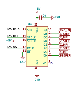
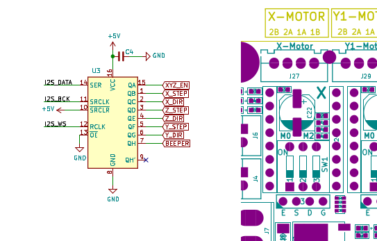
The schematic labels the stepper motor outputs here…
Couldn’t find U3 specified in the documentation, my board, has a 74HC595D serial → serial out or parallel out shift register… for U3. The pin out seems to match.
It looks like it’s output goes to all motor drivers, like connector 3 in the posted composite, E(nable), S(tep), D(irection) and G(round)…
It looks like a typical ttl device… However, the outputs seem to be limited to about 7mA sink… that’s in the middle mA range for the motor drivers inputs… might be a bit iffy…?
Hi all,
Sorry I haven’t been on for a few days. I went and ordered a new board as I tried all the good ideas you have suggested, and guess what? Yep I now have working motors, or motor to be precise. I just need to work out how to set them up properly…
I connected as is recommended, without the ENAble and voila. So I can only presume it must have been the board.