I’m looking to build a sensor for my 3D printer to check the filament is moving.
I’ve bought some optical end stops, and printed an encoder wheel and housing.
I’ve wired the endstop signal to D3 of a NANO, but my code constantly reports the digitalRead == LOW. The red light of the endstop is behaving correctly.
Pin 3 is set to input on the code - and my job is a programmer - so my code is reliable.
I’m wondering if I need a resistor in the circuit ? I’m no particularly proficient with circuit design.
I have tried to use the internal pull ups but no joy.
make sure you are powering it from the same 5V and GND of the Arduino Nano or at the very least you have to have the ground from the power supply and the ground of the Nano connected.
I would have done the same as you, ie set the digital pin as input, set the internal resistor as pull-up and give it a try. The next thing I would do, if you don’t have a volt meter, is to disable the pull-up and look for a low.
A volt meter measuring from gnd to sig with nothing blocking the optical path and then a reading with something blocking the path should tell you what signals to look for on the Arduino input pin.
something we all have to keep an eye on with the controllers and add-on components is their voltage rating. years ago it was all TTL level so 0-5V but over the years lower voltages started being used so using a 5V sensor with a 3.3V Arduino would sometimes burn out the Arduino/rPi input pin.
I believe the Arduino Nano is a 5V device so you should be fine as long as the optical switch is also 5V tolerant(likely).
Just something to be aware of as your addiction to making things with Arduinos and Raspberry Pis grow.
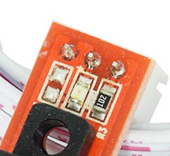
Without a schematic I’d guess it to be an open collector interrupter. Used a home brew version of this on my little CNC machine. Changed to hall effect after junk from the spindle flew it’s way through the interrupter and triggered an error.
I would simply pull the pin to ground, configured as normal. It should detect that and probably fault if it’s trying to home.
Some of these were not a ‘wired or’ configuration, although from the photo, it could be… I read the link, which didn’t say much. There were a couple of comments, translated from German, and indicated he had a problem because the output signal went the wrong way.
It’s an open collector, but I’d guess the resistor and led are on the b+ side with the emitter to ground. So if the output is off the collector and no interruption of the IR beam the photo transistor conducts pulling the output low. This would be the normal state (similar to ‘NC’ on a mechanical switch,) the opposite of what most limit switch inputs are looking for. You can switch what most controllers are looking for but you lose the ‘wired or’ configuration benefit.
I built a few sets of optical and (digital) hall effect limit switches. They worked by a pair of magnets on the table for limits at both ends of the X and Y axes. Pretty simple and straightforward…
However on the Z axis I had an issue with real estate of where to mount the 2 hall switches, 2 sets of cables and the two magnets. I prefer to have the least amount of ‘moving’ wires. I finally placed one hall switch in the center of the z axis and magnets on each end, simulating the switches on each end.
The part holding the magnets no longer uses tape to hold the magnets, but has been modified to look more like a slot you can roll the magnets up and down for a more precise adjustment and more mechanical stability.
The previous mounted optical interrupters required an inverter board attached since it’s output was low normally. On the Z axis I used one interrupter that spanned the entire Z axis, eliminating the need for an inverter and dual switches. Mechanically inverting.
2.2 V is marginal for an input to a Nano if there is no pullup. [is this measured when connected to the arduino?]
I looks to me like the Optocoupler has an open collector that is not pulled up.
No idea why the Ardu internal pullup is not committing the output.
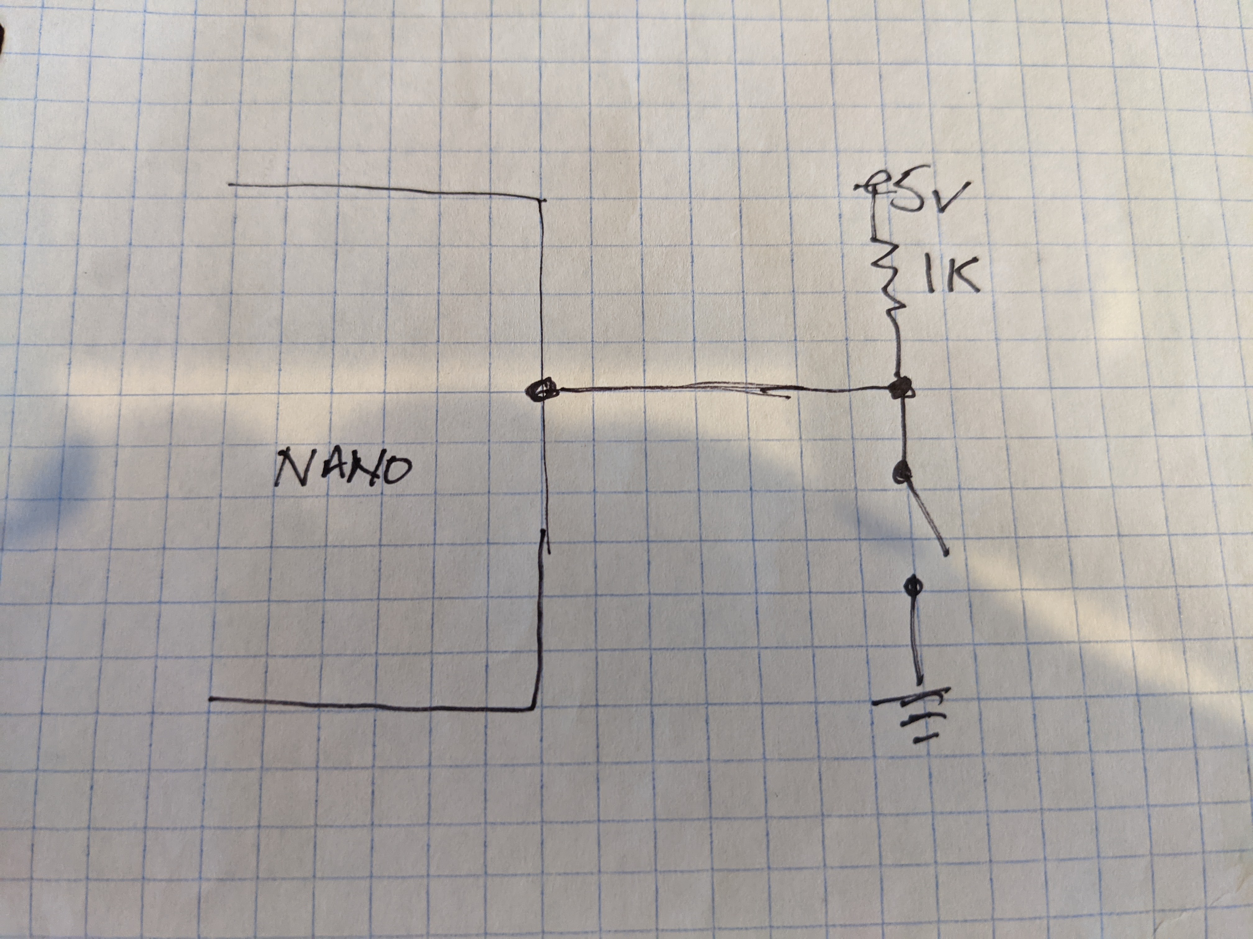
Without it connected to the ardu. you can add a pullup (1K) and read the voltage at the output when interrupted if that give you a full swing of the voltage you know the sensor is good and you problem is on the ardu side.
I switched it to an analogue pin, which gave me a range of 30± when open, and 430± when closed. I just created a bool function which returned false if less than 200, otherwise true.
I’m working on the rest of the logic, and will post links to the STL and code once complete
I’ve seen projects on the net for interfacing optical mouse with arduino.
The issue I am trying to resolve is I get a block, and the extruder can just loop the filament around the gear, or tear it and feed the filament out the top of the extruder.
So my sensor will need to be post extruder and pre nozzle. The filament would need to be enclosed in PTFE to ensure it still feeds correctly (apart from running over the encoder).
I guess I could design it with a mouse sensor and an LED, but the optical endstops are cheap as chips, and there is only 1 moving part involved.
