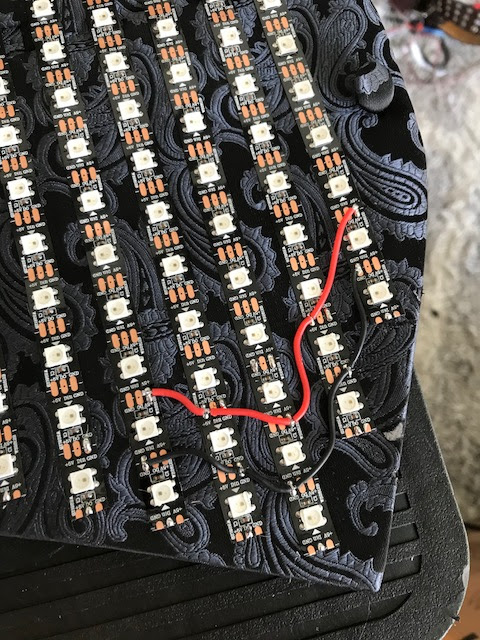
1500 pixel vest I made this weekend, 55 vertical strips ranging from 19 to 36 pixels high.
currently controlled by a ESP8266 D1 mini with 4 way parallel output
powered by a single USB battery outputting 5V 2.4A, which gets it plenty bright enough for indoor parties. Will probably separate into 2 individual circuits for outdoor events, esp Burning Man.
base vest is the cheapest formal/dress vest I could find on amazon prime ($6)
LEDs are ws2812bs 60/m
Thanks to @Randal_B for the idea of making a vest as a base to then wear an other vest or coat or anything over the top rather than building LEDs directly into the outerwear
Now I need to focus on some art and animations. Right now I just have the 2d noise running and a bunch of basic geometrical patterns that I threw together, but none of them are that impressive. If anyone has good suggestions for cool animations to run on a big matrix, please let me know!
Also - of note, up until now I have never had a problem running LEDs with the 3.3v data signal, but when I moved from 2 or 3 way parallel output to 4 way, the data signal degraded enough that it no longer worked at all. Running the data signals through a 74HCT buffer worked perfectly and was much less work than I anticipated. Only issue is that it adds a little bulk to the control wires
@Steve_Anken Definitely on my to-do list! I haven’t dabbled in using the wifi capability of the ESP chips, but I definitely want to figure that out, as well as reading from an SD card, which I haven’t attempted yet but is on the list as well.
Esp32 and BLE is the way to go. No WiFi needed. There is LoRa too for longer distance. There is a WiFi mode that is direct esp32 to esp32 without an AP router.
I think it would be cool to set up a code base for others so they can just plug in and it would scan for other vest wearers. Since you have the beacon strength it would not be hard to change the display depending on proximity to other vest wearers ( or bicycles or whatever is LED lit). It also has easy capacitive touch you could also change it when someone else touches you. A bunch of vest holders could do some fun choreography. An innovative person might even find a way use the collected data from all the participants to create even more interesting emergent patterns.
@Jeremy_Spencer intimidating, but great idea. I have some accelerometers and some MSGEQ7 chips that I ordered awhile back to tinker with, and I ordered some of the breakout boards that @Tommy_Sciano shared from OSH Park. Still need to wrap my head around exactly how I’d utilize the input from the gyroscope or the EQ to translate into cool animations.
and @Steve_Anken - love the idea of choreography… though also intimidated by the idea of building lots of these! Thankfully there’s still a lot of time before August… And I’m definitely making at least one more for my GF - and love the idea of synching us up.
@chad_steinglass , I’m just finishing porting @Jason_Coon 's collection of audio animations to the ESP32 combined with FFT rather than an MSGEQ7 - less hardware I’ve just got to sort out the beat detection…
@Jeremy_Spencer I’ll have to creep on Jason’s github! @Jason_Coon - mind if I dig into some of your 2D animations? if thats cool, where can I find them?
@Yves_BAZIN The LEDs are just attached to the vest with the sticky back that they come with, and then I put a nice big glob of hot glue over the ends of each strip after I soldered on the wires to protect the solder joins and keep the ends of the strips solidly in place. Next time I’ll probably take the time to put a bead of E6000 under the strips for some extra durability. I’ll be wearing it to a party on Saturday and dancing all night - we’ll see how well it holds up!
Also - I’ve been using silicone insulated wire instead of the standard PVC recently. I really like it - so much more flexible, which means less stress on the solder joins.
I like the mario/pacman idea… but I haven’t yet attempted coding for anything like that yet. Do you have any suggestions/examples for reading and displaying GIFs you could point me at?
Could you explain more about the “74HCT buffer”, please? I thought that required 4.5 - 5.5v itself, so how does that help with the 3.3v data signal from the Wimos?
@Christian_Eaton Sure thing - and yes, you power the chip with 5V (I use a USB battery for my 5v power).
The MCU puts out a 3.3v logic signal, but the spec on the WS2812b LED chips is that they need 0.7*Vcc to reliably read a logic level high. Powering LEDs with 5v means that they need a 3.5v data signal to be within spec.
now MOST of the time they work fine with 3.3v, even though its technically not within spec.
I’m guessing that when you ask the wimos to work harder and put data output signals on a bunch of pins in parallel, perhaps the voltage level starts to fluctuate a little, enough so that the signal that was barely working before, now starts to fall apart.
Regardless, the result is some corruption of the data signal, such that the LEDs might interpret a 1 as a 0 here and there, and then everything goes to crap after that as the corrupt signal propagates through the strip, causing epilepsy inducing nastiness.
The 74HCT chip has an input logic high voltage of 2v, so the data signal from the wimos is well within spec. The chip then outputs a 5v signal on the output pins, which you then use to drive the LEDs. (ha sorry - this last paragraph is probably all you needed to know!)

 I’ve just got to sort out the beat detection…